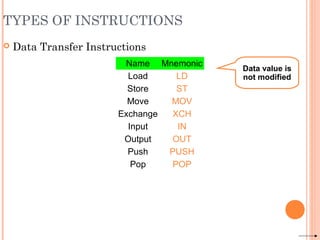
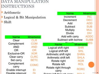
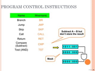
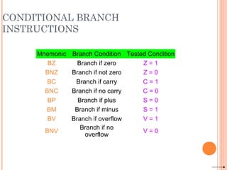
Downloaded 24 times
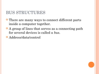
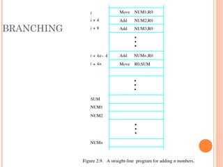
![FIVE EXECUTION STEPS
Step nameStep name Action for R-typeAction for R-type
instructionsinstructions
Action for Memory-Action for Memory-
reference Instructionsreference Instructions
Action forAction for
branchesbranches
Action forAction for
jumpsjumps
Instruction fetch IR = MEM[PC]
PC = PC + 4
Instruction decode/ register
fetch
A = Reg[IR[25-21]]
B = Reg[IR[20-16]]
ALUOut = PC + (sign extend (IR[15-0])<<2)
Execution, address
computation, branch/jump
completion
ALUOut = A op B ALUOut = A+sign
extend(IR[15-0])
IF(A==B) Then
PC=ALUOut
PC=PC[31-
28]||(IR[25-
0]<<2)
Memory access or R-type
completion
Reg[IR[15-11]] =
ALUOut
Load:MDR =Mem[ALUOut]
or
Store:Mem[ALUOut] = B
Memory read completion Load: Reg[IR[20-16]] =
MDR](https://image.slidesharecdn.com/basicstructureofcomputersbyaniketbhute-160628125649/85/Basic-structure-of-computers-by-aniket-bhute-9-320.jpg)


![REGISTER TRANSFER NOTATION
Identify a location by a symbolic name standing for its
hardware binary address (LOC, R0,…)
Contents of a location are denoted by placing square
brackets around the name of the location (R1←[LOC],
R3 ←[R1]+[R2])
Register Transfer Notation (RTN)](https://image.slidesharecdn.com/basicstructureofcomputersbyaniketbhute-160628125649/85/Basic-structure-of-computers-by-aniket-bhute-59-320.jpg)
![ASSEMBLY LANGUAGE NOTATION
Represent machine instructions and programs.
Move LOC, R1 = R1←[LOC]
Add R1, R2, R3 = R3 ←[R1]+[R2]](https://image.slidesharecdn.com/basicstructureofcomputersbyaniketbhute-160628125649/85/Basic-structure-of-computers-by-aniket-bhute-60-320.jpg)
![INSTRUCTION FORMATS
Three-Address Instructions
ADD R1, R2, R3 R1 ← R2 + R3
Two-Address Instructions
ADD R1, R2 R1 ← R1 + R2
One-Address Instructions
ADD M AC ← AC + M[AR]
Zero-Address Instructions
ADD TOS ← TOS + (TOS – 1)
RISC Instructions
Lots of registers. Memory is restricted to Load & Store
Opcode Operand(s) or Address(es)](https://image.slidesharecdn.com/basicstructureofcomputersbyaniketbhute-160628125649/85/Basic-structure-of-computers-by-aniket-bhute-62-320.jpg)
![INSTRUCTION FORMATS
Example: Evaluate (A+B) ∗ (C+D)
Three-Address
1. ADD R1, A, B ; R1 ← M[A] + M[B]
2. ADD R2, C, D ; R2 ← M[C] + M[D]
3. MUL X, R1, R2 ; M[X] ← R1 ∗ R2](https://image.slidesharecdn.com/basicstructureofcomputersbyaniketbhute-160628125649/85/Basic-structure-of-computers-by-aniket-bhute-63-320.jpg)
![INSTRUCTION FORMATS
Example: Evaluate (A+B) ∗ (C+D)
Two-Address
1. MOV R1, A ; R1 ← M[A]
2. ADD R1, B ; R1 ← R1 + M[B]
3. MOV R2, C ; R2 ← M[C]
4. ADD R2, D ; R2 ← R2 + M[D]
5. MUL R1, R2 ; R1 ← R1 ∗ R2
6. MOV X, R1 ; M[X] ← R1](https://image.slidesharecdn.com/basicstructureofcomputersbyaniketbhute-160628125649/85/Basic-structure-of-computers-by-aniket-bhute-64-320.jpg)
![INSTRUCTION FORMATS
Example: Evaluate (A+B) ∗ (C+D)
One-Address
1. LOAD A ; AC ← M[A]
2. ADD B ; AC ← AC + M[B]
3. STORE T ; M[T] ← AC
4. LOAD C ; AC ← M[C]
5. ADD D ; AC ← AC + M[D]
6. MUL T ; AC ← AC ∗ M[T]
7. STORE X ; M[X] ← AC](https://image.slidesharecdn.com/basicstructureofcomputersbyaniketbhute-160628125649/85/Basic-structure-of-computers-by-aniket-bhute-65-320.jpg)
![INSTRUCTION FORMATS
Example: Evaluate (A+B) ∗ (C+D)
Zero-Address
1. PUSH A ; TOS ← A
2. PUSH B ; TOS ← B
3. ADD ; TOS ← (A + B)
4. PUSH C ; TOS ← C
5. PUSH D ; TOS ← D
6. ADD ; TOS ← (C + D)
7. MUL ; TOS ← (C+D)∗(A+B)
8. POP X ; M[X] ← TOS](https://image.slidesharecdn.com/basicstructureofcomputersbyaniketbhute-160628125649/85/Basic-structure-of-computers-by-aniket-bhute-66-320.jpg)
![INSTRUCTION FORMATS
Example: Evaluate (A+B) ∗ (C+D)
RISC
1. LOAD R1, A ; R1 ← M[A]
2. LOAD R2, B ; R2 ← M[B]
3. LOAD R3, C ; R3 ← M[C]
4. LOAD R4, D ; R4 ← M[D]
5. ADD R1, R1, R2 ; R1 ← R1 + R2
6. ADD R3, R3, R4 ; R3 ← R3 + R4
7. MUL R1, R1, R3 ; R1 ← R1 ∗ R3
8. STORE X, R1 ; M[X] ← R1](https://image.slidesharecdn.com/basicstructureofcomputersbyaniketbhute-160628125649/85/Basic-structure-of-computers-by-aniket-bhute-67-320.jpg)
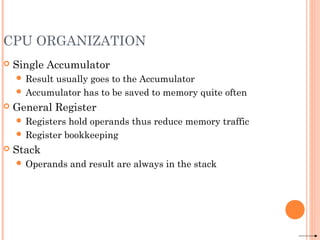
![INSTRUCTION EXECUTION AND
STRAIGHT-LINE SEQUENCING
R0,C
B,R0
A,R0
Movei + 8
Begin execution here Movei
ContentsAddress
C
B
A
the program
Data for
segment
program
3instruction
Addi + 4
Figure 2.8. A program for C ← [Α] + [Β].
Assumptions:
- One memory operand
per instruction
- 32-bit word length
- Memory is byte
addressable
- Full memory address
can be directly specified
in a single-word instruction
Two-phase procedure
-Instruction fetch
-Instruction execute
Page 43](https://image.slidesharecdn.com/basicstructureofcomputersbyaniketbhute-160628125649/85/Basic-structure-of-computers-by-aniket-bhute-69-320.jpg)

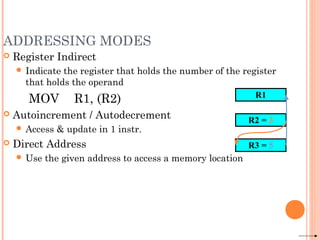
![ADDRESSING MODES
Implied
AC is implied in “ADD M[AR]” in “One-Address” instr.
TOS is implied in “ADD” in “Zero-Address” instr.
Immediate
The use of a constant in “MOV R1, 5”, i.e. R1 ← 5
Register
Indicate which register holds the operand
Opcode Mode ...](https://image.slidesharecdn.com/basicstructureofcomputersbyaniketbhute-160628125649/85/Basic-structure-of-computers-by-aniket-bhute-77-320.jpg)
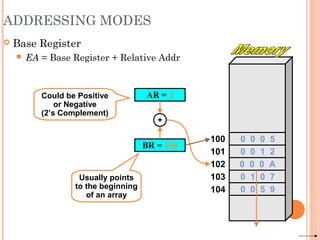
![ADDRESSING MODES
The different
ways in which
the location of
an operand is
specified in
an instruction
are referred
to as
addressing
modes.
Name Assem bler syn tax Addressing function
Immediate #Value Operand = Value
Register Ri EA = Ri
Absolute(Direct) LOC EA = LOC
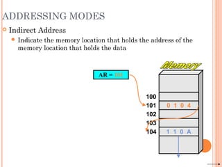
Indirect (Ri ) EA = [Ri ]
(LOC) EA = [LOC]
Index X(Ri) EA = [Ri ] + X
Basewith index (Ri ,Rj ) EA = [Ri ] + [Rj ]
Basewith index X(Ri,Rj ) EA = [Ri ] + [Rj ] + X
and offset
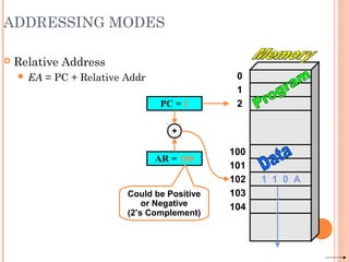
Relative X(PC) EA = [PC] + X
Autoincrement (Ri )+ EA = [Ri ] ;
Increment Ri
Autodecrement (Ri ) Decrement Ri ;
EA = [Ri]
−](https://image.slidesharecdn.com/basicstructureofcomputersbyaniketbhute-160628125649/85/Basic-structure-of-computers-by-aniket-bhute-83-320.jpg)
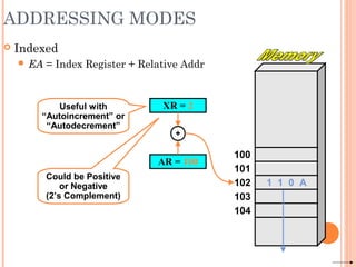
![INDEXING AND ARRAYS
Index mode – the effective address of the operand
is generated by adding a constant value to the
contents of a register.
Index register
X(Ri): EA = X + [Ri]
The constant X may be given either as an explicit
number or as a symbolic name representing a
numerical value.
If X is shorter than a word, sign-extension is
needed.](https://image.slidesharecdn.com/basicstructureofcomputersbyaniketbhute-160628125649/85/Basic-structure-of-computers-by-aniket-bhute-84-320.jpg)
![INDEXING AND ARRAYS
In general, the Index mode facilitates access to an
operand whose location is defined relative to a
reference point within the data structure in which the
operand appears.
Several variations:
(Ri, Rj): EA = [Ri] + [Rj]
X(Ri, Rj): EA = X + [Ri] + [Rj]](https://image.slidesharecdn.com/basicstructureofcomputersbyaniketbhute-160628125649/85/Basic-structure-of-computers-by-aniket-bhute-85-320.jpg)
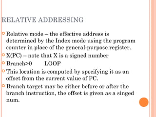
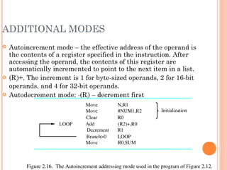

![DATA TRANSFER INSTRUCTIONS
Mode Assembly Register Transfer
Direct address LD ADR AC ← M[ADR]
Indirect address LD @ADR AC ← M[M[ADR]]
Relative address LD $ADR AC ← M[PC+ADR]
Immediate operand LD #NBR AC ← NBR
Index addressing LD ADR(X) AC ← M[ADR+XR]
Register LD R1 AC ← R1
Register indirect LD (R1) AC ← M[R1]
Autoincrement LD (R1)+ AC ← M[R1], R1 ← R1+1](https://image.slidesharecdn.com/basicstructureofcomputersbyaniketbhute-160628125649/85/Basic-structure-of-computers-by-aniket-bhute-90-320.jpg)


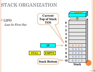
![STACK ORGANIZATION
PUSH
SP ← SP – 1
M[SP] ← DR
If (SP = 0) then (FULL ← 1)
EMPTY ← 0
SP
Stack Bottom
Current
Top of Stack
TOS 0
1
2
3
4
7
8
9
10
5
6
Stack
0 0 5 5
0 0 0 8
0 0 2 5
0 0 1 5
0 1 2 3
FULL EMPTY
1 6 9 0
1 6 9 0Current
Top of Stack
TOS](https://image.slidesharecdn.com/basicstructureofcomputersbyaniketbhute-160628125649/85/Basic-structure-of-computers-by-aniket-bhute-104-320.jpg)
![STACK ORGANIZATION
POP
DR ← M[SP]
SP ← SP + 1
If (SP = 11) then (EMPTY ← 1)
FULL ← 0
SP
Stack Bottom
Current
Top of Stack
TOS 0
1
2
3
4
7
8
9
10
5
6
Stack
0 0 5 5
0 0 0 8
0 0 2 5
0 0 1 5
0 1 2 3
FULL EMPTY
1 6 9 01 6 9 0
Current
Top of Stack
TOS](https://image.slidesharecdn.com/basicstructureofcomputersbyaniketbhute-160628125649/85/Basic-structure-of-computers-by-aniket-bhute-105-320.jpg)
![0
1
2
102
202
201
200
100
101
STACK ORGANIZATION
Memory Stack
PUSH
SP ← SP – 1
M[SP] ← DR
POP
DR ← M[SP]
SP ← SP + 1
PC
AR
SP](https://image.slidesharecdn.com/basicstructureofcomputersbyaniketbhute-160628125649/85/Basic-structure-of-computers-by-aniket-bhute-106-320.jpg)
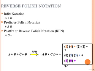
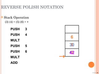
![REVERSE POLISH NOTATION
Example
(A + B) ∗ [C ∗ (D + E) + F]
(A B +) (D E +) C
∗
∗F +](https://image.slidesharecdn.com/basicstructureofcomputersbyaniketbhute-160628125649/85/Basic-structure-of-computers-by-aniket-bhute-108-320.jpg)

![MULTIPLICATION AND DIVISION
Not very popular (especially division)
Multiply Ri, Rj
Rj ← [Ri] х [Rj]
2n-bit product case: high-order half in R(j+1)
Divide Ri, Rj
Rj ← [Ri] / [Rj]
Quotient is in Rj, remainder may be placed in R(j+1)](https://image.slidesharecdn.com/basicstructureofcomputersbyaniketbhute-160628125649/85/Basic-structure-of-computers-by-aniket-bhute-114-320.jpg)

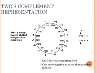
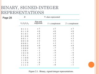
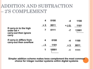
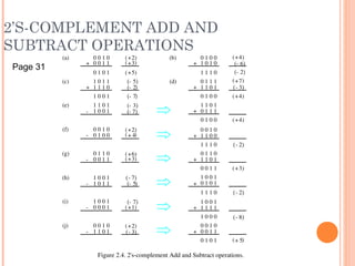
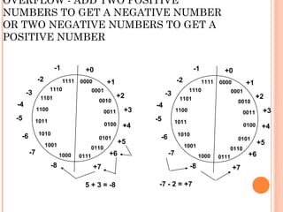
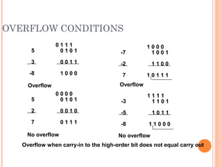
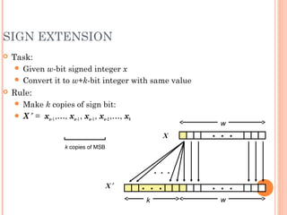
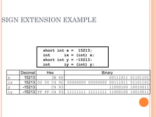
The document summarizes the basic structure and functional units of computers. It discusses how computers handle information through instructions and data. The main functional units that process information are the memory unit, arithmetic and logic unit (ALU), and control unit. It also describes the number representation systems used in computers, focusing on the two's complement system for signed integers. Addition and subtraction are performed through two's complement arithmetic.