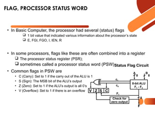
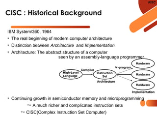
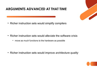
The document discusses computer organization focusing on the central processing unit (CPU), including aspects like general register organization, instruction formats, addressing modes, and the role of flags in the processor state. It contrasts complex instruction set computers (CISC) with reduced instruction set computers (RISC), highlighting the differences in instruction complexity, memory access, and execution models. The document also addresses program control methods, interrupts, and the architecture's evolution, illustrating how these concepts impact CPU design and performance.

![SUBROUTINE CALL AND RETURN
Call subroutine
Jump to subroutine
Branch to subroutine
Branch and save return address
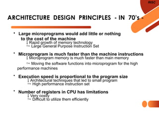
• Fixed Location in the subroutine (Memory)
• Fixed Location in memory
• In a processor Register
• In memory stack
- most efficient way
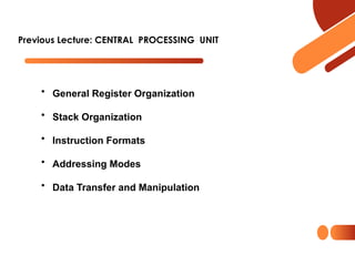
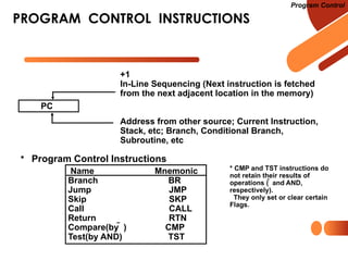
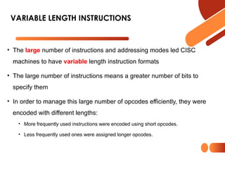
Program Control
• Subroutine Call
• Two Most Important Operations are Implied;
* Branch to the beginning of the Subroutine
- Same as the Branch or Conditional Branch
* Save the Return Address to get the address
of the location in the Calling Program upon
exit from the Subroutine
• Locations for storing Return Address
CALL
SP SP - 1
M[SP] PC
PC EA
RTN
PC M[SP]
SP SP + 1](https://image.slidesharecdn.com/2024lecture12come321-241123085941-67c04708/85/2024_lecture12_come321-pptx-8-320.jpg)
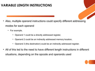
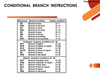
![• Another characteristic of CISC computers is that they have instructions
that act directly on memory addresses
• For example,
ADD L1, L2, L3
that takes the contents of M[L1] adds it to the contents of M[L2] and stores the result
in location M[L3]
• An instruction like this takes three memory access cycles to execute
• That makes for a potentially very long instruction execution cycle
• The problems with CISC computers are
• The complexity of the design may slow down the processor,
• The complexity of the design may result in costly errors in the processor design and
implementation,
• Many of the instructions and addressing modes are used rarely, if ever
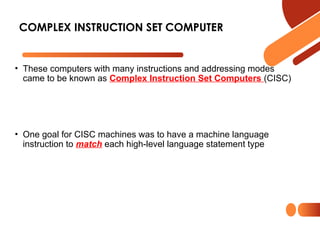
COMPLEX INSTRUCTION SET COMPUTER](https://image.slidesharecdn.com/2024lecture12come321-241123085941-67c04708/85/2024_lecture12_come321-pptx-21-320.jpg)