Download as PDF, PPTX

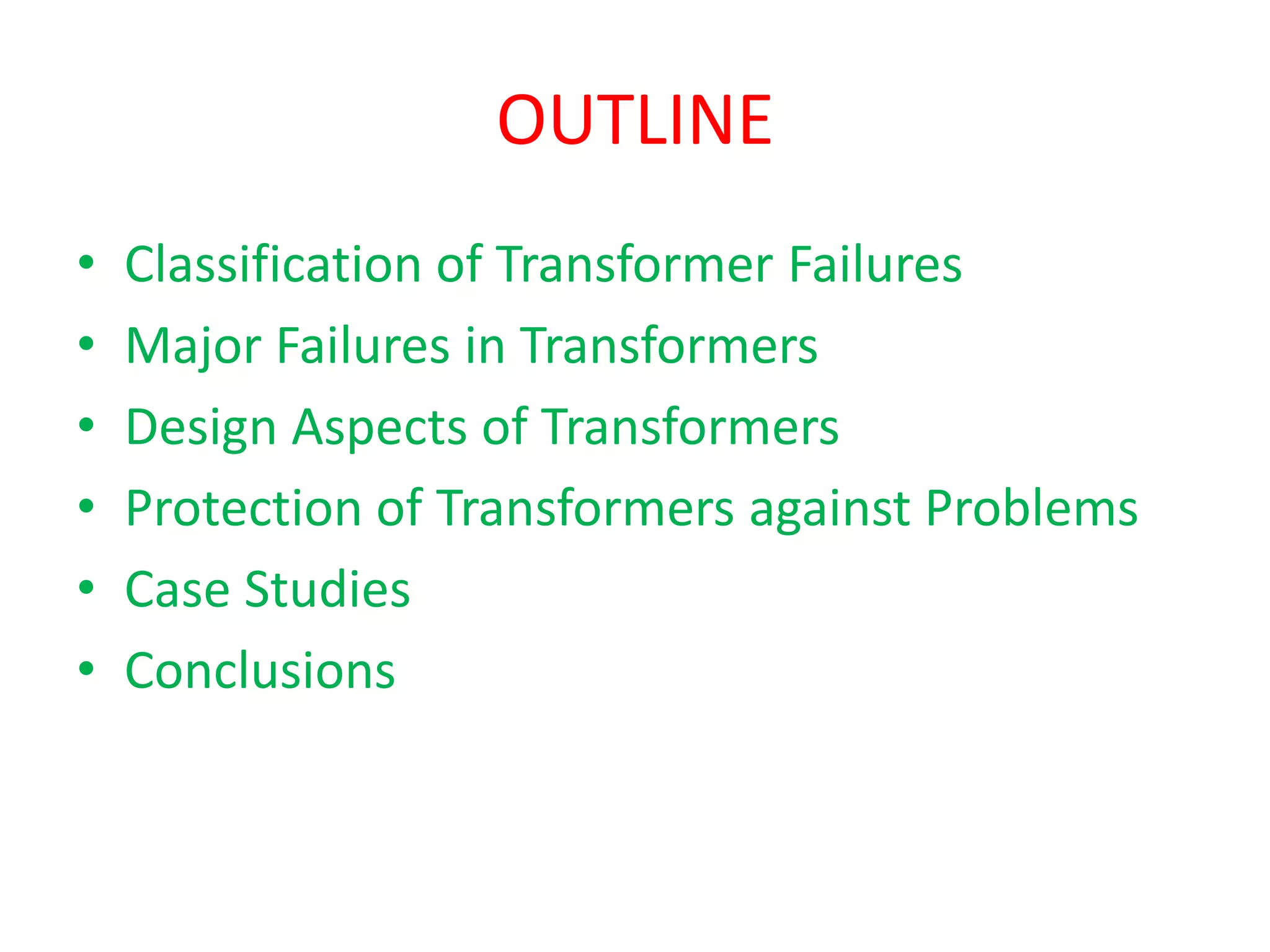
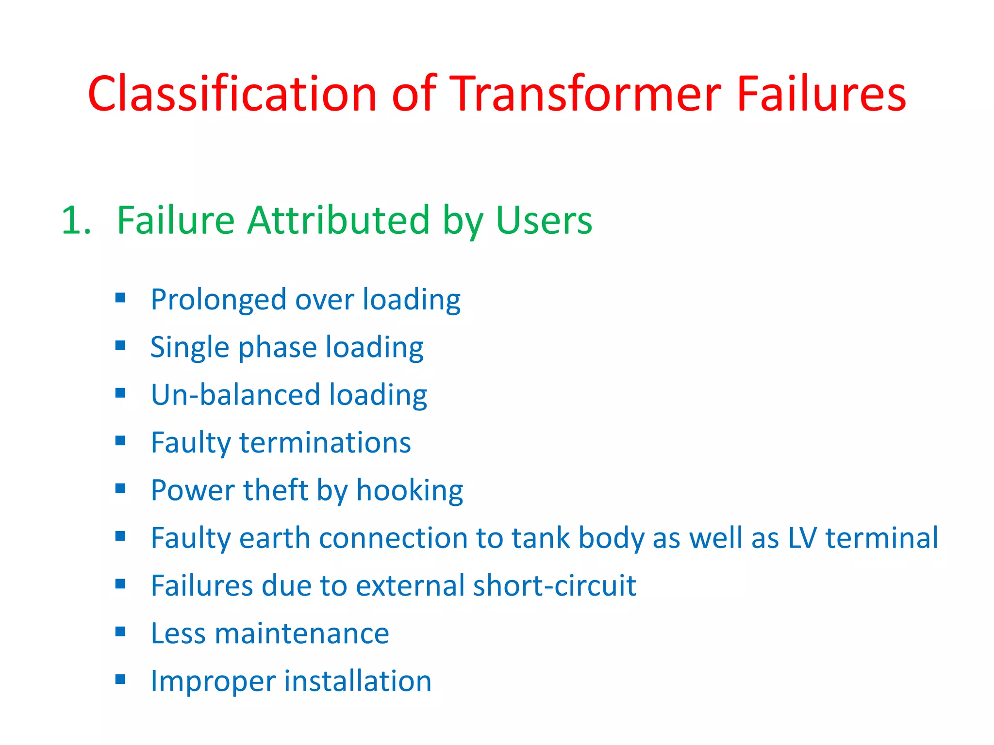
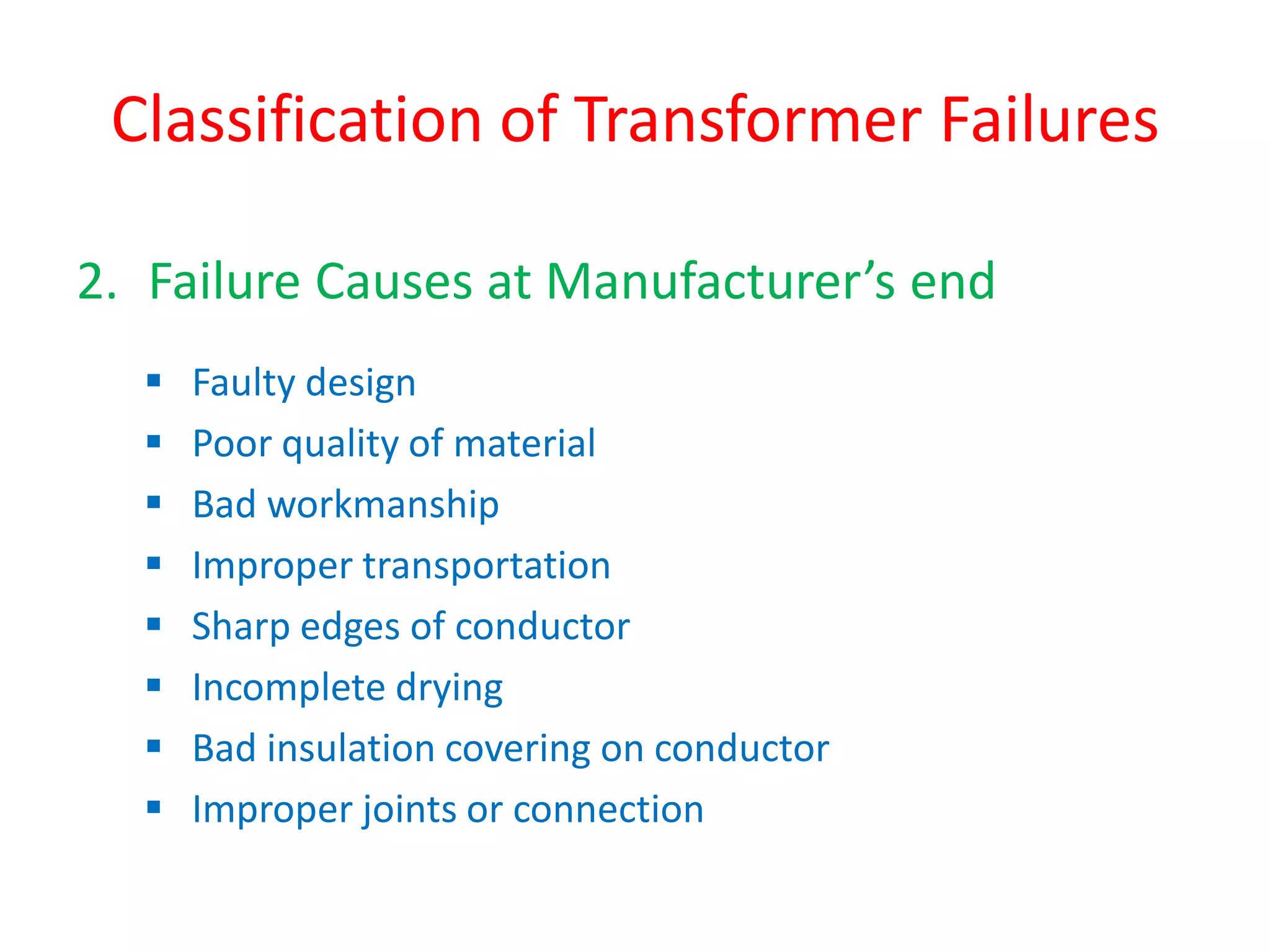

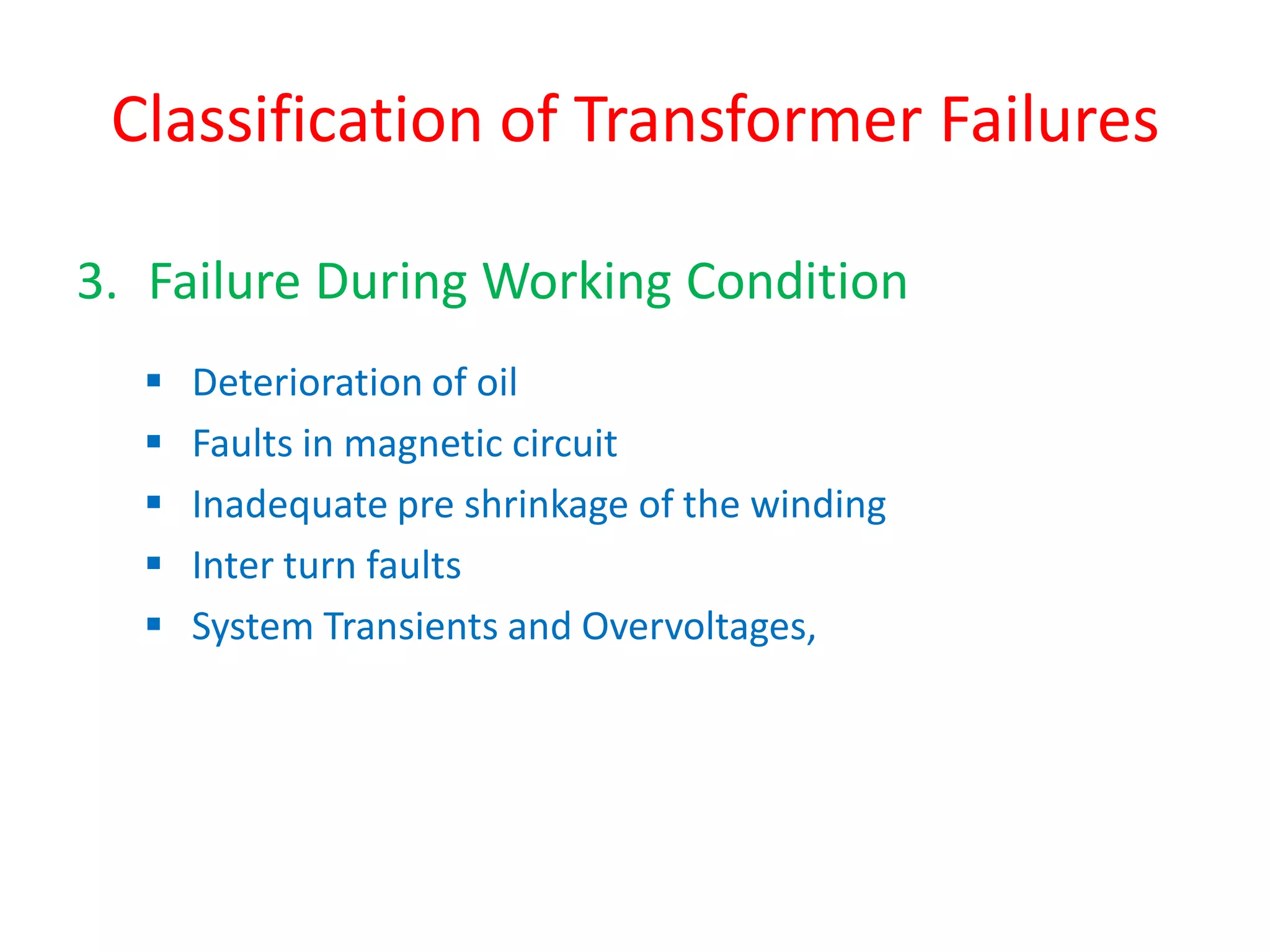
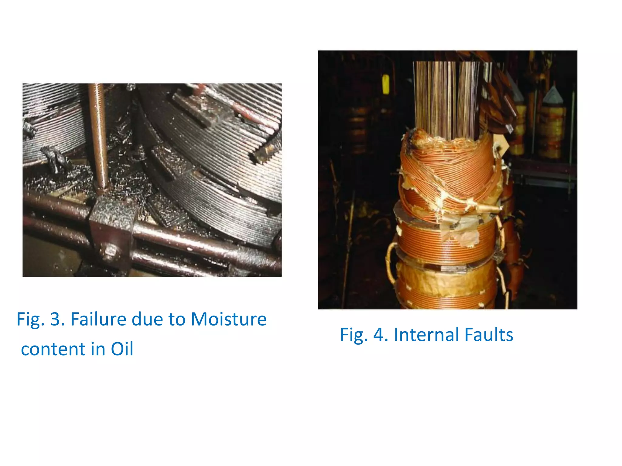


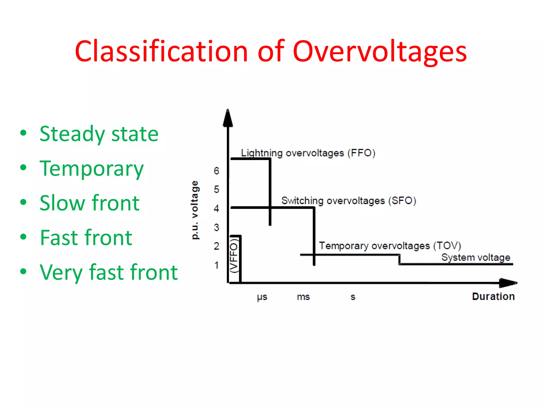
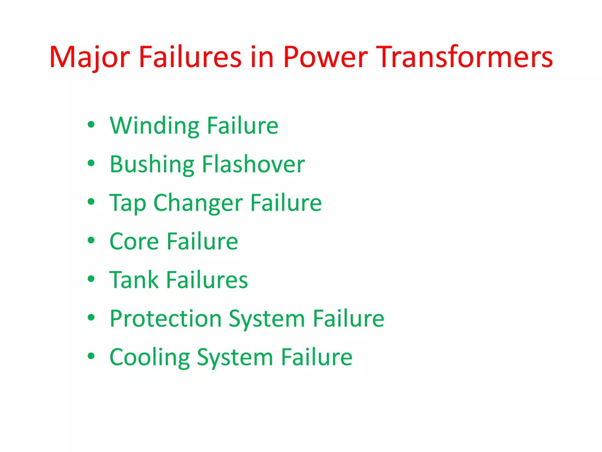
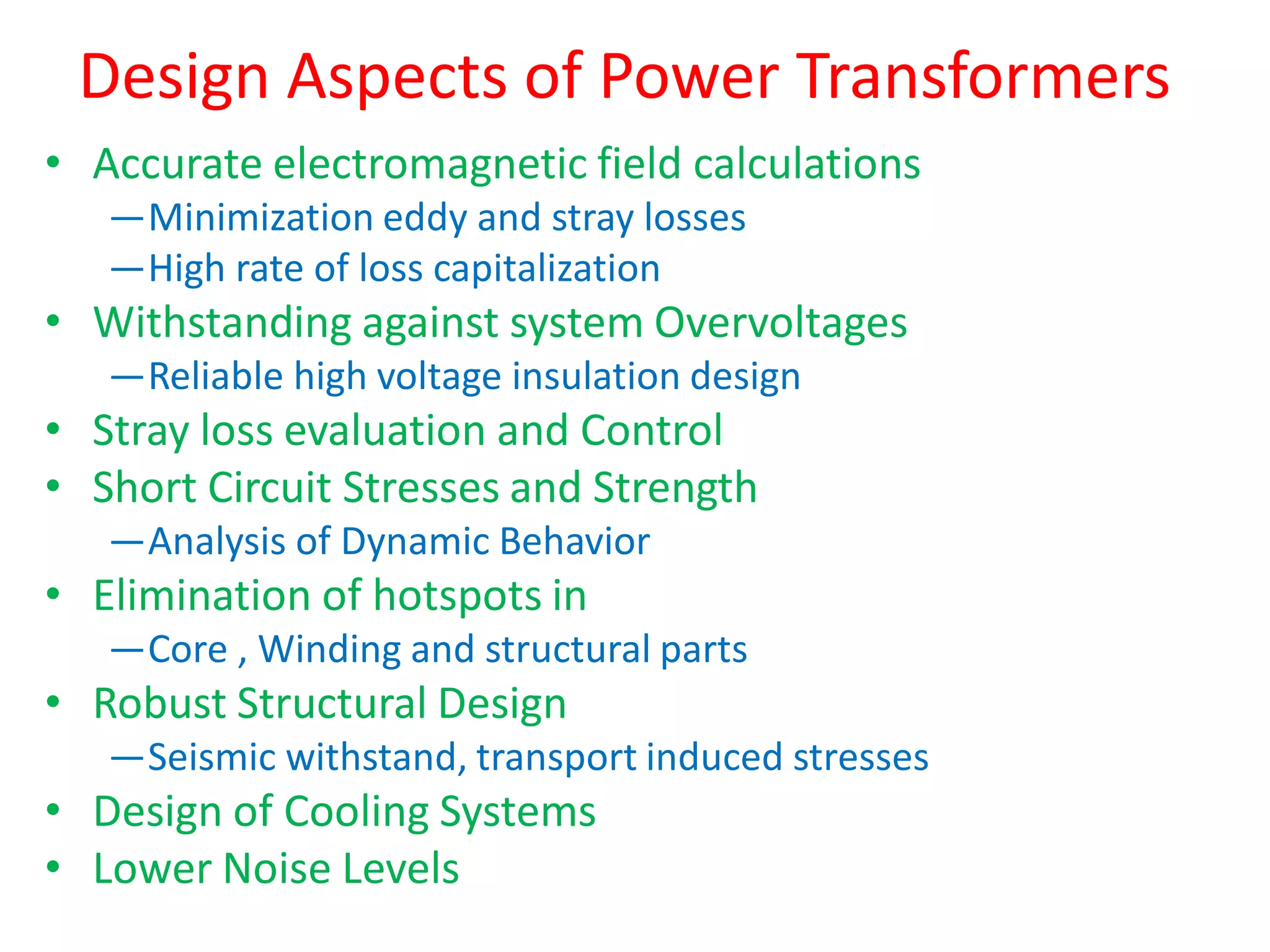


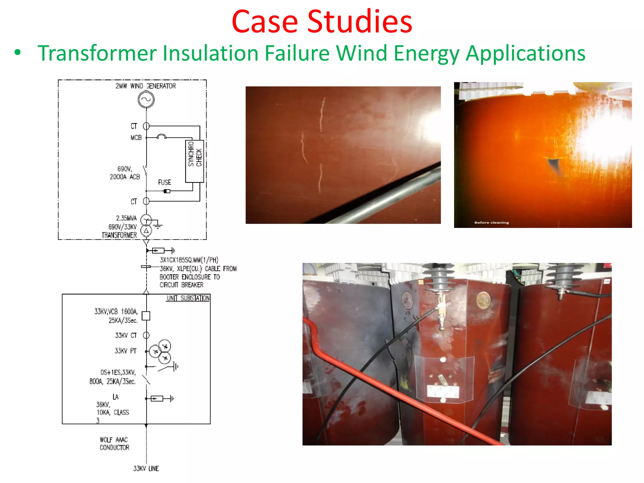


The document discusses various transformer failures, categorizing them into user-related, manufacturer-related, and operational issues while highlighting major failure types like winding failures and bushing flashovers. It also covers design considerations and protective measures against overvoltages and mechanical stresses, concluding with case studies illustrating failures and the importance of adequate maintenance and design. Key takeaways emphasize the need for proper workmanship and protective devices to mitigate risks.


![Transformer Repair Workshop Report [EEE]](https://cdn.slidesharecdn.com/ss_thumbnails/transformerrepairworkshopeee-140621072318-phpapp01-thumbnail.jpg?width=640&height=640&fit=bounds)