Downloaded 31 times


![Inspection [Pre-test, Intermediate]
This inspection as a minimum shall include thorough
visual examination of the equipment to ensure correct
assembly of all the components, proper calibration of
the assembly, proper calibration of test equipment,
security of fasteners, adequacy of power supply and
appropriateness of all control settings etc.](https://image.slidesharecdn.com/bhavsar-seismictest-180521051740/75/Seismic-qualification-of-equipment-by-testing-Bhavsar-32-2048.jpg)


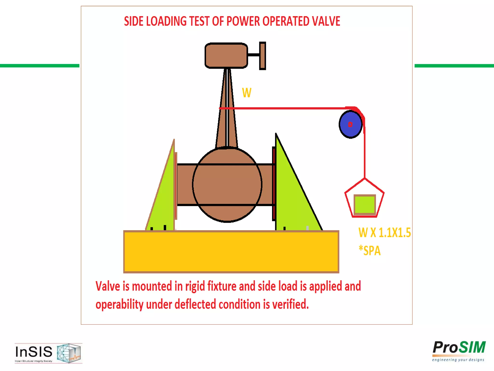
![Functional Checks [Pre, Post, Intermediate]
1. Opening or closing of electrical contacts & timing
2. Opening or closing of valves & timing
3. Various outputs indications on volt meter/ampere
meter etc.
4. Operation of limit switches
5. Actuation of mechanical/electrical operation etc.
6. Any other peculiar function to be performed by
equipment as per the specification of equipment e.g. in
case of valves opening closing time should be monitored.](https://image.slidesharecdn.com/bhavsar-seismictest-180521051740/75/Seismic-qualification-of-equipment-by-testing-Bhavsar-35-2048.jpg)

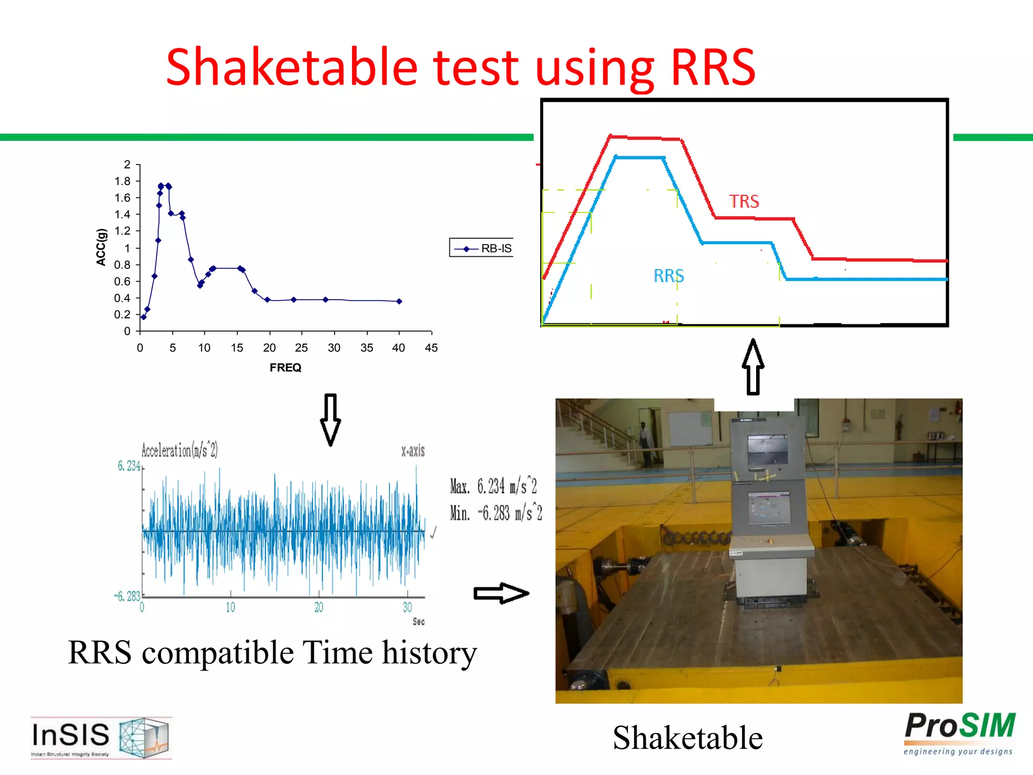
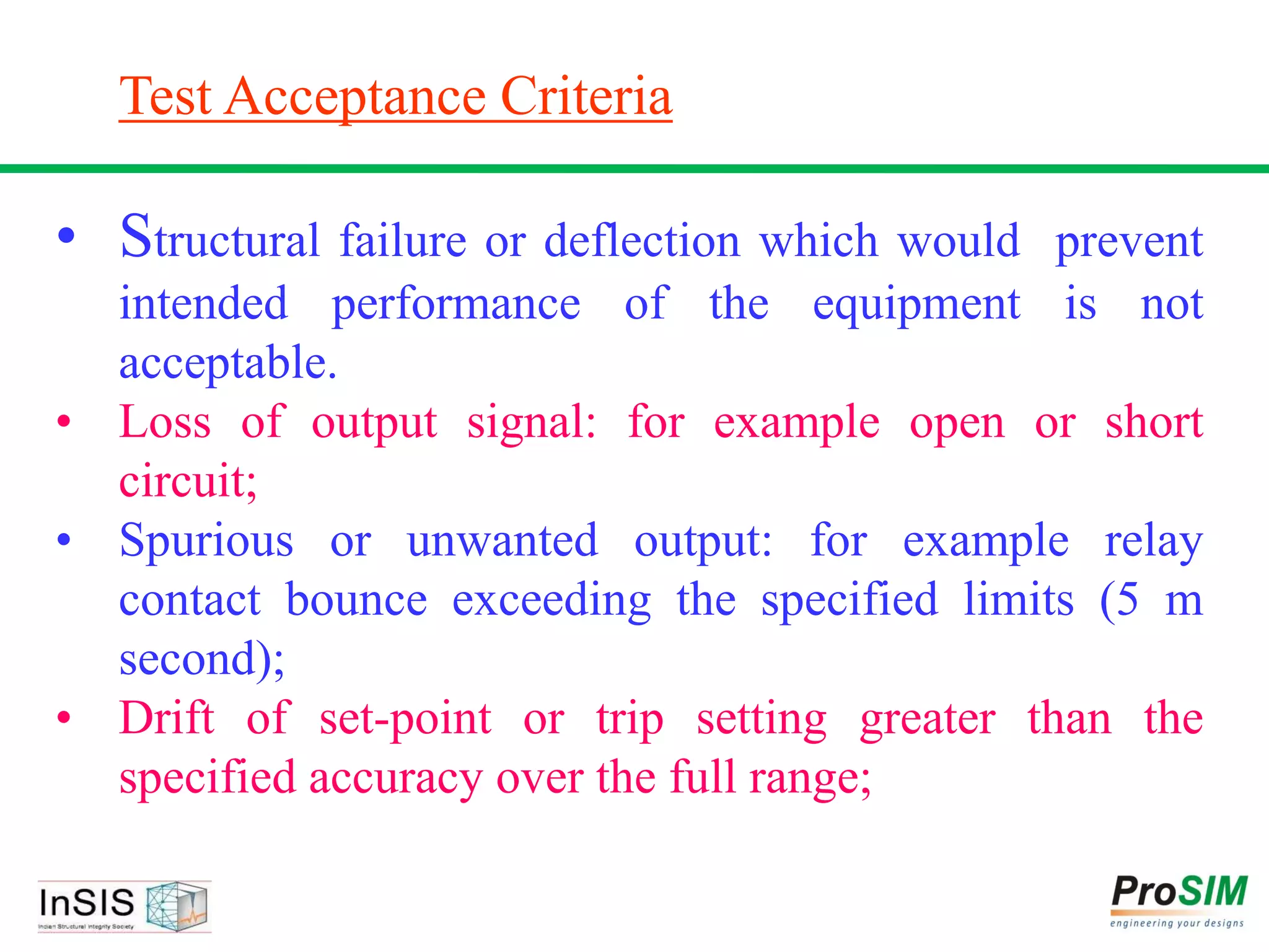


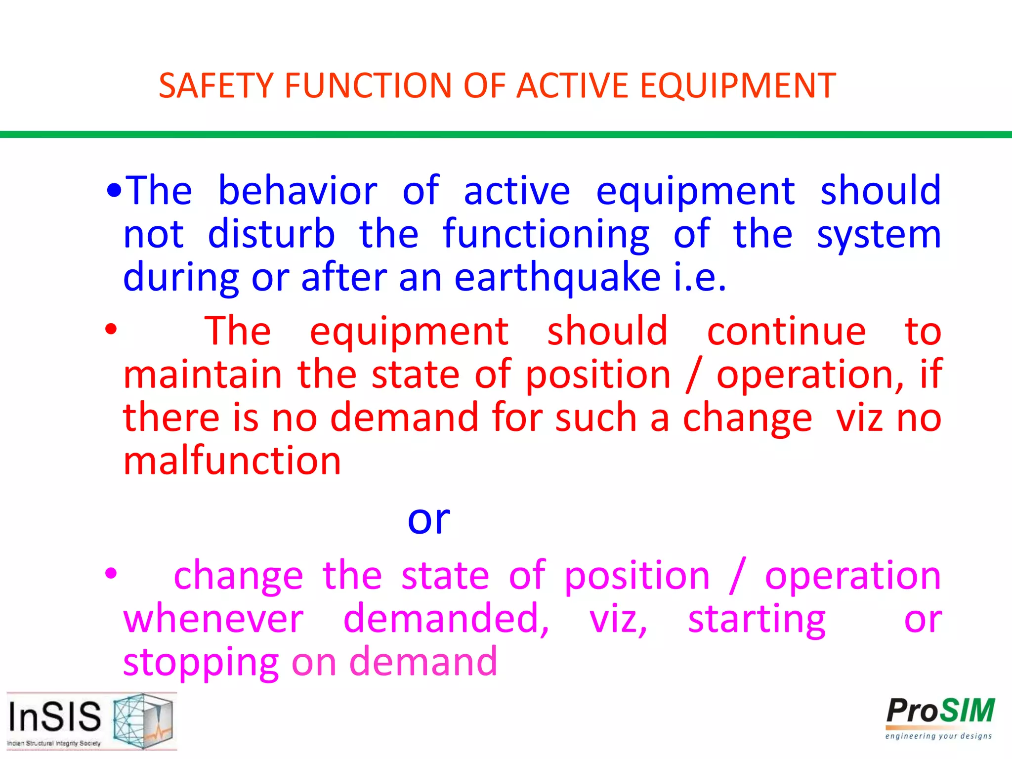
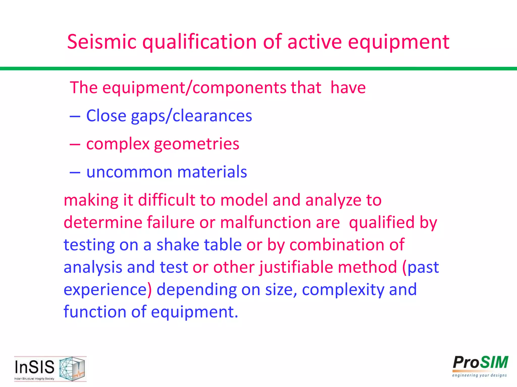
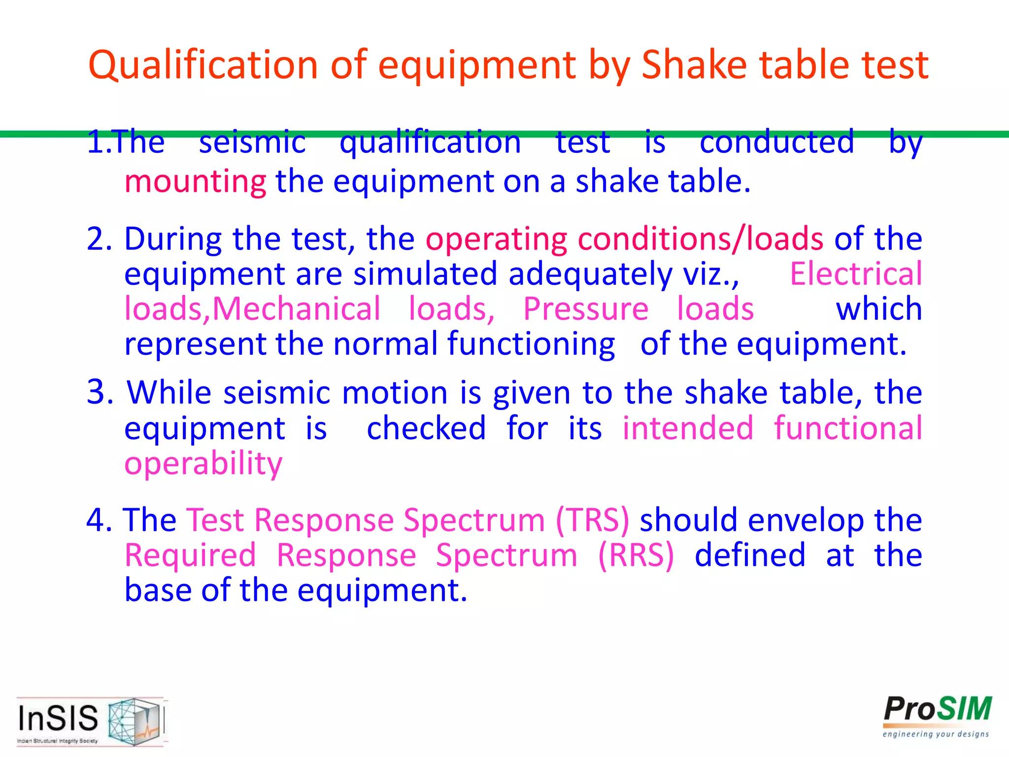
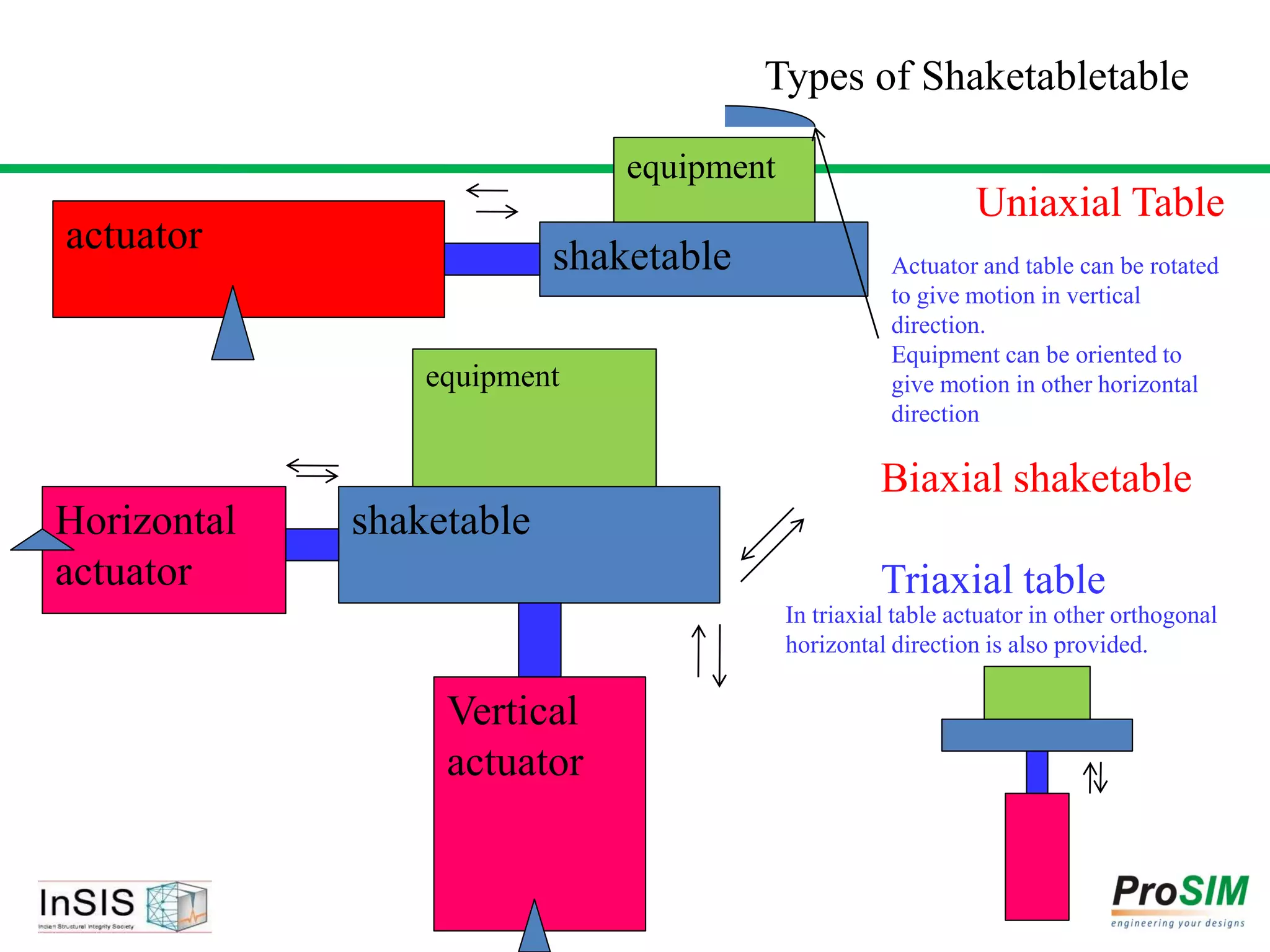
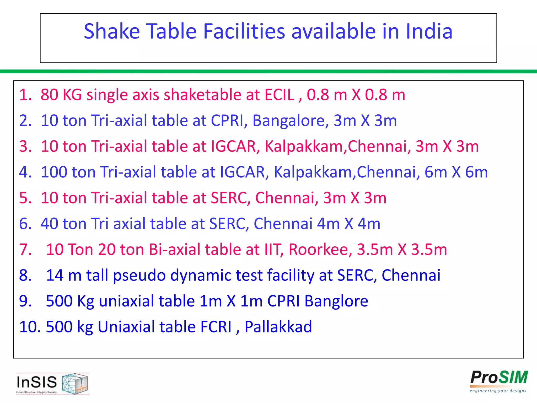
The document summarizes methods for seismic qualification of equipment through testing. Key points include: - Equipment is tested on a shake table that simulates earthquake ground motions to show it can withstand forces and perform safety functions. - Tests are conducted under operating loads while monitoring for structural integrity and functional performance. - Acceptance is based on no failures, within performance limits, and the test response spectrum enveloping the required response spectrum.


