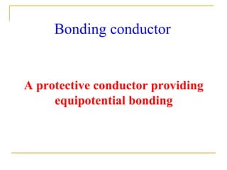
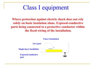
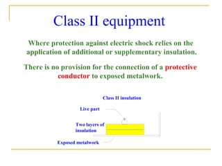
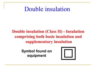
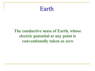
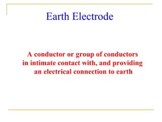
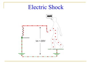
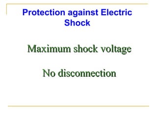
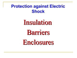
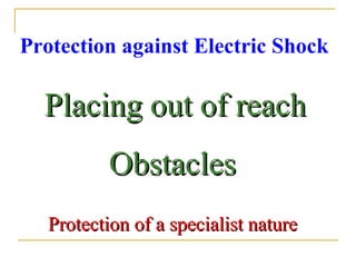
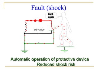
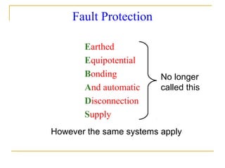
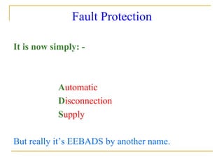
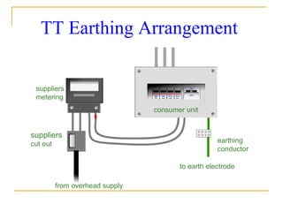
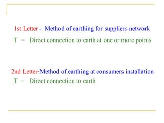
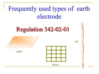
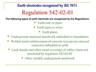
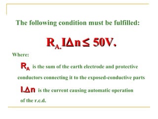
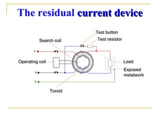
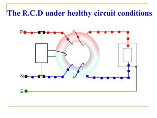
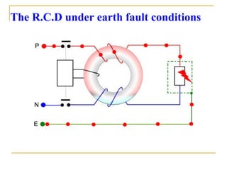
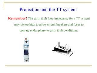
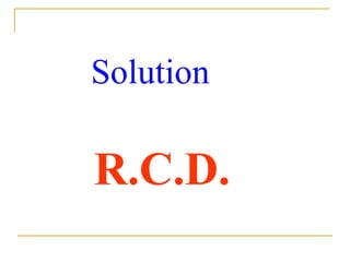
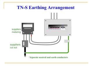
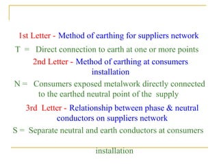
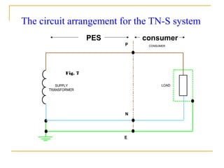
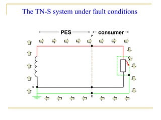
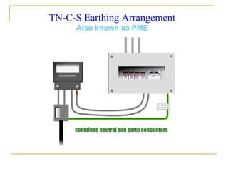
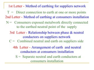
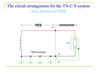
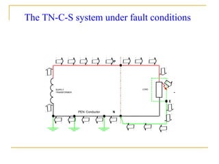
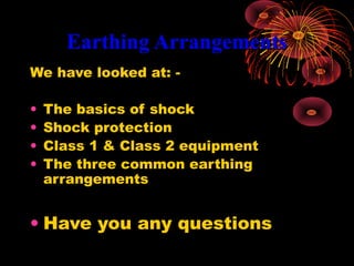
Earthing ArrangementsEarthing Arrangements
In this section we are going
to look at : -
 The basics of shock
 Shock protection
 Class 1 & Class 2 equipment
 The three common earthing arrangements
Earthing arrangements - always a good talking
point!
Definitions from Part 2 BS 7671Definitions from Part 2 BS 7671
Bonding conductor
A protective conductor providing
equipotential bonding
Where protection against electric shock does not rely
solely on basic insulation alone. Exposed-conductive
parts being connected to a protective conductor within
the fixed wiring of the installation.
Class I equipment
Class I insulation
Single-layer insulation
Live part
Exposed conductive
part
Class II equipment
Where protection against electric shock relies on the
application of additional or supplementary insulation.
There is no provision for the connection of a protective
conductor to exposed metalwork.
Class II insulation
Live part
Two layers of
insulation
Exposed metalwork
Double insulation
Double insulation (Class II) - Insulation
comprising both basic insulation and
supplementary insulation
Symbol found on
equipment
Earth
The conductive mass of Earth, whose
electric potential at any point is
conventionally taken as zero
Earth Electrode
A conductor or group of conductors
in intimate contact with, and providing
an electrical connection to earth
Earth electrode resistance
The resistance of an earth
electrode to earth
Earth fault current
A fault current which flows to earth
Earth fault loop impedance
The impedance of the earth fault current
loop starting and ending at the point of
earth fault.
Symbol ZSymbol Z
UnitUnit ΩΩ
The earth fault loop
The earth fault loop starting at the point of fault
consists of:
• The circuit protective conductor (c.p.c.)
• Consumers earthing terminal and earthing conductor
• For TN systems, the metallic return path
• For TT and IT systems the earth return path
• The path through the earthed neutral point of the
transformer
• The transformer winding and phase conductor to point
of fault
Earth leakage current
A current which flows to earth, or to
extraneous conductive parts, in a circuit
which is electrically sound. This current
may have a capacitive quality including that
from the deliberate use of capacitors for
noise filtration.
Earthed equipotential zone
A zone within which exposed conductive parts and
extraneous conductive parts are maintained at
substantially the same potential by bonding, such
that under fault conditions, the differences in potential
simultaneously accessible exposed and extraneous-
conductive parts will not cause electric shock.
Earthing
Connection of the exposed conductive parts
of an installation to the main earthing
terminal of that installation
Basic contact (shock)
Results from
Making contact with parts of a circuit orMaking contact with parts of a circuit or
system which are live under normal conditionssystem which are live under normal conditions
Earthing
Connection of the exposed conductive
parts of an installation to the main earthing
terminal of that
installation
Extraneous conductive part
A conductive part liable to introduce a
potential, generally earth potential, and not
forming part of the electrical installation.
Fault
A circuit condition in which current flows through an
abnormal or unintended path.
This may result from an
insulation failure or a bridging of insulation.
Conventionally the impedance between live conductors or
between live conductors and exposed or extraneous
conductive parts at the fault position is considered
negligible.
Functional earthing
Connection to Earth necessary for proper
functioning of electrical equipment
Table 51ATable 51A
Functional earthing conductors to be
coloured cream
Contact of persons or livestock with
exposed-conductive parts which have
become live under fault conditions.
Fault contact
Protective conductors
A conductor used for some measure of protection against
electric shock and intended for connecting together any
of the following parts
• Exposed conductive parts
• Extraneous-conductive parts
• The main earthing terminal
• Earth electrode(s)
• The earthed point of the source, or an artificial neutral
Protective conductors
Earthing conductor
main bonding
conductor
circuit protective
conductor
Shock conditionsShock conditions
Electric Shock
Contact of persons or livestock with live parts
under fault free conditions.
Uo = 230V
Electric Shock
ouchouch
Protection against Electric
Shock
Maximum shock voltageMaximum shock voltage
No disconnectionNo disconnection
Protection against Electric
Shock
InsulationInsulation
BarriersBarriers
EnclosuresEnclosures
Protection against Electric Shock
Placing out of reachPlacing out of reach
ObstaclesObstacles
Protection of a specialist natureProtection of a specialist nature
Uo = 230V
Fault (shock)
Automatic operation of protective deviceAutomatic operation of protective device
Reduced shock riskReduced shock risk
OuchOuch
againagain
Fault Protection
Earthed
Equipotential
Bonding
And automatic
Disconnection
Supply
No longer
called this
However the same systems apply
Fault Protection
It is now simply: -
Automatic
Disconnection
Supply
But really it’s EEBADS by another name.
Earthing ArrangementsEarthing Arrangements
TT Earthing Arrangement
suppliers
cut out
suppliers
metering
earthing
conductor
from overhead supply
to earth electrode
consumer unit
1st Letter - Method of earthing for suppliers network
2nd Letter-Method of earthing at consumers installation
T = Direct connection to earth at one or more points
T = Direct connection to earth
Frequently used types of earth
electrode
plate
lattice
rod
Regulation 542-02-01Regulation 542-02-01
Earth electrodes recognised by BS 7671Earth electrodes recognised by BS 7671
The following types of earth electrode are recognised by the Regulations:
Regulation 542-02-01
 Earth rods or pipes
 Earth tapes or wires
 Earth plates
 Underground structural metalwork embedded in foundations
 Welded metal reinforcement of concrete (except pre-stressed
concrete) embedded in earth
 Lead sheaths and other metal coverings of cables where not
precluded by regulation 542-02-05
 Other suitable underground metalwork
Installation of earth electrodes
When installing earth electrodes the following precautions
should be observed
Regulation 542-02-02
Remember climatic conditions could affect electrode
resistance
The type and embedded depth of an earth electrode shall be
sufficient to avoid soil drying and freezing
Earth electrode resistance
The graph illustrates the relationship between electrode
resistance and buried depth for a ‘rod type’ electrode. The deeper
the rod, the closer to the water table it becomes, resulting in lower
resistance
Typical value of resistance of
‘rod type’ electrode buried to
a depth of 1 metre (60 Ω
approx.)
Reducing earth electrode resistanceReducing earth electrode resistance
Under certain circumstances the value of electrode
resistance may be excessively high and steps must be
taken to reduce its value. The following methods may
be adopted:
• use of extendable rods
• use of additional rods
• soil conditioning agents (temporary measure)
• electrodes buried to a greater depth
Use of additional rods to reduce resistance
As a ‘rule of thumb’, the distance between adjacent earth rods
should not be less than the buried depth.
Distance (m)
Depth (m)
Earthing
conductor
Problems associated with the TT system
Vulnerable to mechanical damage
Vulnerable to corrosion
High resistance as compared toHigh resistance as compared to
TN systemsTN systems
Use of the residual current device
Regulation 413-02-19
Preferred method of protection against indirect contact,
by means of residual current device.
Calculating touch voltage
Maximum permitted touch voltage = 50V unless
special location. (max 25V)
Regulation 413-02-20
The following condition must be fulfilled:
RRA.A.II∆∆nn ≤≤ 50V.50V.
Where:
RRAA is the sum of the earth electrode and protective
conductors connecting it to the exposed-conductive parts
I.I.∆∆nn is the current causing automatic operation
of the r.c.d.
REMEMBER
50V max, or
25V max
The residual current devicecurrent device
LoadLoad
ExposedExposed
metalworkmetalwork
Test resistorTest resistor
Test buttonTest button
Search coilSearch coil
ToroidToroid
Operating coilOperating coil
The R.C.D under healthy circuit conditions
The R.C.D under earth fault conditions
Protection and the TT system
Remember! The earth fault loop impedance for a TT system
may be too high to allow circuit breakers and fuses to
operate under phase to earth fault conditions.
Solution
R.C.D.
TN-S Earthing Arrangement
Separate neutral and earth conductors
suppliers
cut out
suppliers
metering
1st Letter - Method of earthing for suppliers network
2nd Letter - Method of earthing at consumers
installation
T = Direct connection to earth at one or more points
N = Consumers exposed metalwork directly connected
to the earthed neutral point of the supply
3rd Letter - Relationship between phase & neutral
conductors on suppliers network
S = Separate neutral and earth conductors at consumers
installation
PES consumer
The circuit arrangement for the TN-S system
Fig. 7
PES consumer
The TN-S system under fault conditions
TN-C-S Earthing Arrangement
Also known as PME
combined neutral and earth conductors
1st Letter - Method of earthing for suppliers network
2nd Letter - Method of earthing at consumers installation
T = Direct connection to earth at one or more points
N = Consumers exposed metalwork directly connected
to the earthed neutral point of the supply
3rd Letter - Relationship between phase & neutral
conductors on suppliers network
C = Combined neutral and earth on suppliers side
4th Letter - Arrangement of earth and neutral
conductors at consumers installation
S = Separate neutral and earth conductors at
consumers installation
PES consumer
PEN conductor
The circuit arrangement for the TN-C-S system
Also known as PME
The TN-C-S system under fault conditions
Earthing ArrangementsEarthing Arrangements
We have looked at: -
• The basics of shock
• Shock protection
• Class 1 & Class 2 equipment
• The three common earthing
arrangements
• Have you any questions

Earthing Arrangements

  • 1.
  • 2.
    In this sectionwe are going to look at : -  The basics of shock  Shock protection  Class 1 & Class 2 equipment  The three common earthing arrangements
  • 3.
    Earthing arrangements -always a good talking point!
  • 4.
    Definitions from Part2 BS 7671Definitions from Part 2 BS 7671
  • 5.
    Bonding conductor A protectiveconductor providing equipotential bonding
  • 6.
    Where protection againstelectric shock does not rely solely on basic insulation alone. Exposed-conductive parts being connected to a protective conductor within the fixed wiring of the installation. Class I equipment Class I insulation Single-layer insulation Live part Exposed conductive part
  • 7.
    Class II equipment Whereprotection against electric shock relies on the application of additional or supplementary insulation. There is no provision for the connection of a protective conductor to exposed metalwork. Class II insulation Live part Two layers of insulation Exposed metalwork
  • 8.
    Double insulation Double insulation(Class II) - Insulation comprising both basic insulation and supplementary insulation Symbol found on equipment
  • 9.
    Earth The conductive massof Earth, whose electric potential at any point is conventionally taken as zero
  • 10.
    Earth Electrode A conductoror group of conductors in intimate contact with, and providing an electrical connection to earth
  • 11.
    Earth electrode resistance Theresistance of an earth electrode to earth
  • 12.
    Earth fault current Afault current which flows to earth
  • 13.
    Earth fault loopimpedance The impedance of the earth fault current loop starting and ending at the point of earth fault. Symbol ZSymbol Z UnitUnit ΩΩ
  • 14.
    The earth faultloop The earth fault loop starting at the point of fault consists of: • The circuit protective conductor (c.p.c.) • Consumers earthing terminal and earthing conductor • For TN systems, the metallic return path • For TT and IT systems the earth return path • The path through the earthed neutral point of the transformer • The transformer winding and phase conductor to point of fault
  • 15.
    Earth leakage current Acurrent which flows to earth, or to extraneous conductive parts, in a circuit which is electrically sound. This current may have a capacitive quality including that from the deliberate use of capacitors for noise filtration.
  • 16.
    Earthed equipotential zone Azone within which exposed conductive parts and extraneous conductive parts are maintained at substantially the same potential by bonding, such that under fault conditions, the differences in potential simultaneously accessible exposed and extraneous- conductive parts will not cause electric shock.
  • 17.
    Earthing Connection of theexposed conductive parts of an installation to the main earthing terminal of that installation
  • 18.
    Basic contact (shock) Resultsfrom Making contact with parts of a circuit orMaking contact with parts of a circuit or system which are live under normal conditionssystem which are live under normal conditions
  • 19.
    Earthing Connection of theexposed conductive parts of an installation to the main earthing terminal of that installation
  • 20.
    Extraneous conductive part Aconductive part liable to introduce a potential, generally earth potential, and not forming part of the electrical installation.
  • 21.
    Fault A circuit conditionin which current flows through an abnormal or unintended path. This may result from an insulation failure or a bridging of insulation. Conventionally the impedance between live conductors or between live conductors and exposed or extraneous conductive parts at the fault position is considered negligible.
  • 22.
    Functional earthing Connection toEarth necessary for proper functioning of electrical equipment Table 51ATable 51A Functional earthing conductors to be coloured cream
  • 23.
    Contact of personsor livestock with exposed-conductive parts which have become live under fault conditions. Fault contact
  • 24.
    Protective conductors A conductorused for some measure of protection against electric shock and intended for connecting together any of the following parts • Exposed conductive parts • Extraneous-conductive parts • The main earthing terminal • Earth electrode(s) • The earthed point of the source, or an artificial neutral
  • 25.
    Protective conductors Earthing conductor mainbonding conductor circuit protective conductor
  • 26.
  • 27.
    Electric Shock Contact ofpersons or livestock with live parts under fault free conditions.
  • 28.
    Uo = 230V ElectricShock ouchouch
  • 29.
    Protection against Electric Shock Maximumshock voltageMaximum shock voltage No disconnectionNo disconnection
  • 30.
  • 31.
    Protection against ElectricShock Placing out of reachPlacing out of reach ObstaclesObstacles Protection of a specialist natureProtection of a specialist nature
  • 32.
    Uo = 230V Fault(shock) Automatic operation of protective deviceAutomatic operation of protective device Reduced shock riskReduced shock risk OuchOuch againagain
  • 33.
  • 34.
    Fault Protection It isnow simply: - Automatic Disconnection Supply But really it’s EEBADS by another name.
  • 35.
  • 36.
    TT Earthing Arrangement suppliers cutout suppliers metering earthing conductor from overhead supply to earth electrode consumer unit
  • 37.
    1st Letter -Method of earthing for suppliers network 2nd Letter-Method of earthing at consumers installation T = Direct connection to earth at one or more points T = Direct connection to earth
  • 38.
    Frequently used typesof earth electrode plate lattice rod Regulation 542-02-01Regulation 542-02-01
  • 39.
    Earth electrodes recognisedby BS 7671Earth electrodes recognised by BS 7671 The following types of earth electrode are recognised by the Regulations: Regulation 542-02-01  Earth rods or pipes  Earth tapes or wires  Earth plates  Underground structural metalwork embedded in foundations  Welded metal reinforcement of concrete (except pre-stressed concrete) embedded in earth  Lead sheaths and other metal coverings of cables where not precluded by regulation 542-02-05  Other suitable underground metalwork
  • 40.
    Installation of earthelectrodes When installing earth electrodes the following precautions should be observed Regulation 542-02-02 Remember climatic conditions could affect electrode resistance The type and embedded depth of an earth electrode shall be sufficient to avoid soil drying and freezing
  • 41.
    Earth electrode resistance Thegraph illustrates the relationship between electrode resistance and buried depth for a ‘rod type’ electrode. The deeper the rod, the closer to the water table it becomes, resulting in lower resistance Typical value of resistance of ‘rod type’ electrode buried to a depth of 1 metre (60 Ω approx.)
  • 42.
    Reducing earth electroderesistanceReducing earth electrode resistance Under certain circumstances the value of electrode resistance may be excessively high and steps must be taken to reduce its value. The following methods may be adopted: • use of extendable rods • use of additional rods • soil conditioning agents (temporary measure) • electrodes buried to a greater depth
  • 43.
    Use of additionalrods to reduce resistance As a ‘rule of thumb’, the distance between adjacent earth rods should not be less than the buried depth. Distance (m) Depth (m) Earthing conductor
  • 44.
    Problems associated withthe TT system Vulnerable to mechanical damage Vulnerable to corrosion High resistance as compared toHigh resistance as compared to TN systemsTN systems
  • 45.
    Use of theresidual current device Regulation 413-02-19 Preferred method of protection against indirect contact, by means of residual current device.
  • 46.
    Calculating touch voltage Maximumpermitted touch voltage = 50V unless special location. (max 25V) Regulation 413-02-20
  • 47.
    The following conditionmust be fulfilled: RRA.A.II∆∆nn ≤≤ 50V.50V. Where: RRAA is the sum of the earth electrode and protective conductors connecting it to the exposed-conductive parts I.I.∆∆nn is the current causing automatic operation of the r.c.d.
  • 48.
  • 49.
    The residual currentdevicecurrent device LoadLoad ExposedExposed metalworkmetalwork Test resistorTest resistor Test buttonTest button Search coilSearch coil ToroidToroid Operating coilOperating coil
  • 50.
    The R.C.D underhealthy circuit conditions
  • 51.
    The R.C.D underearth fault conditions
  • 52.
    Protection and theTT system Remember! The earth fault loop impedance for a TT system may be too high to allow circuit breakers and fuses to operate under phase to earth fault conditions.
  • 53.
  • 54.
    TN-S Earthing Arrangement Separateneutral and earth conductors suppliers cut out suppliers metering
  • 55.
    1st Letter -Method of earthing for suppliers network 2nd Letter - Method of earthing at consumers installation T = Direct connection to earth at one or more points N = Consumers exposed metalwork directly connected to the earthed neutral point of the supply 3rd Letter - Relationship between phase & neutral conductors on suppliers network S = Separate neutral and earth conductors at consumers installation
  • 56.
    PES consumer The circuitarrangement for the TN-S system Fig. 7
  • 57.
    PES consumer The TN-Ssystem under fault conditions
  • 58.
    TN-C-S Earthing Arrangement Alsoknown as PME combined neutral and earth conductors
  • 59.
    1st Letter -Method of earthing for suppliers network 2nd Letter - Method of earthing at consumers installation T = Direct connection to earth at one or more points N = Consumers exposed metalwork directly connected to the earthed neutral point of the supply 3rd Letter - Relationship between phase & neutral conductors on suppliers network C = Combined neutral and earth on suppliers side 4th Letter - Arrangement of earth and neutral conductors at consumers installation S = Separate neutral and earth conductors at consumers installation
  • 60.
    PES consumer PEN conductor Thecircuit arrangement for the TN-C-S system Also known as PME
  • 61.
    The TN-C-S systemunder fault conditions
  • 62.
    Earthing ArrangementsEarthing Arrangements Wehave looked at: - • The basics of shock • Shock protection • Class 1 & Class 2 equipment • The three common earthing arrangements • Have you any questions