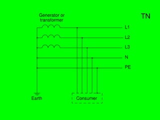
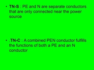
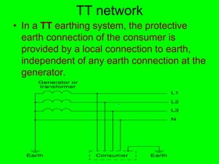
Earthing system
• A protective earth( PE) connection ensures that
all exposed conductive surfaces are at the
same electrical potential as the surface of the
Earth, to avoid the risk of electrical shock if a
person touches a device in which an insulation
fault has occurred. It also ensures that in the
case of an insulation fault, a high fault current
flows, which will trigger an overcurrent
protection device (fuse, MCB) that disconnects
the power supply .
1. A functional earth connection serves a
purpose other than providing protection
against electrical shock .In contrast to a
protective earth connection, a functional earth
connection may carry a current during the
normal operation of a device. Functional earth
connections may be required by devices such
as surge suppression and electromagnetic-
compatibility filters, some types of antennas
and various measurement instruments.
Generally the protective earth is also used as
a functional earth though this requires care in
some situ
IEC nomenclature
• The first letter indicates the connection between earth
and the power-supply equipment (generator or
transformer:)
• T : direct connection of a point with earth (French: terre
• I : no point is connected with earth (isolation), except
perhaps via a high impedance
• .The second letter indicates the connection between
earth and the electrical device being supplied:
• T : direct connection with earth, independent of any other
earth connection in the supply system
• N : connection to earth via the supply network
TN network
• In a TN earthing system, one of the points
in the generator or transformer is
connected with earth, usually the star point
in a three-phase system. The body of the
electrical device is connected with earth
via this earth connection at the transformer
• ‫به‬ ‫ژنراتور‬ ‫يا‬ ‫ترانسفورماتور‬ ‫صفر‬ ‫نقطه‬ ‫سيستم‬ ‫اين‬ ‫در‬
‫از‬ ‫زمين‬ ‫به‬ ‫نيز‬ ‫تجهيزات‬ ‫وبدنه‬ ‫گردد‬ ‫مي‬ ‫متصل‬ ‫زمين‬
‫گردد‬ ‫مي‬ ‫وصل‬ ‫سيستم‬ ‫اين‬ ‫طريق‬
TN
• The conductor that connects the exposed
metallic parts of the consumer is called
protective earth PE
• .The conductor that connects to the star
point in a three-phase system, or that
carries the return current in a single-
phase system is called neutral N
• .Three variants of TN systems are
distinguished:
• TN-S : PE and N are separate conductors
that are only connected near the power
source
• .TN-C : A combined PEN conductor fulfills
the functions of both a PE and an N
conductor
• TN-C-S : Part of the system uses a
combined PEN conductor, which is at
some point split up into separate PE and N
lines. The combined PEN conductor
typically occurs between the substation
and the entry point into the building,
whereas within the building separate PE
and N conductors are used. (In the UK,
this system is also known as protective
multiple earthing (PME )
, because of the
practice of connecting the combined
neutral and earth to real earth at many
locations to reduce the risk of broken
neutrals).
TN-S :separate protective earth (PE) and
neutral (N) conductors from transformer to
consuming device, which are not
connected at any point after the building
distribution point.
• TN-C :combined PE and N conductor all
the way from the transformer to the
consuming device .
.
• TN-C-S earthing system :combined PEN
conductor from transformer to building
distribution point, but separate PE and N
conductors in fixed indoor wiring and
flexible power cords .
TN
K
I
I a
n 
Ia
In
K
K=2.5
K=1.25
TT network
• In a TT earthing system, the protective
earth connection of the consumer is
provided by a local connection to earth,
independent of any earth connection at the
generator.
.
IT network
• In an IT network, the distribution system
has no connection to earth at all, or it has
only a high impedance connection.
•
:
(
1
. )
TT
(
TT
)
.
TT
.
.
TT
.
:
V
I
R a
A 50


:) (
Ia
:) (
.
Ia
n
a I
I 

.
.
Ia
5
.
Ia
.
(
. )
.
. » «
) ( .
20
.
5
5
15
(
/ /
1
/
5
/
0
/
10
5
/
1
Properties
• TN networks save the cost of a low-impedance
earth connection at the site of each consumer.
Such a connection (a buried metal structure) is
required to provide protective earth in IT and TT
systems .
• TN-C networks save the cost of an additional
conductor needed for separate N and PE
connections. However to mitigate the risk of
broken neutrals, special cable types and lots of
connections to earth are needed .
• TT networks require RCD protection and often
an expensive time delay type is needed to
provide discrimination with an RCD downstream
Safety
• In TN an insulation fault is very likely to lead to
a high short-circuit current that will trigger an
overcurrent circuit-breaker or fuse and
disconnect the L conductors.
• In the majority of TT systems the earth fault
loop impedance will be too high to do this and
so an RCD must be employed
• In TN-S and TT systems (and in TN-C-S
beyond the point of the split), a residual-
current device can be used as an
additional protection. In the absence of
any insulation fault in the consumer
device, the equation IL1+IL2+IL3+IN =
0
holds, and an RCD can disconnect the
supply as soon as this sum reaches a
threshold (typically 10-500 mA). An
insulation fault between either L or N and
PE will trigger an RCD with high
probability
• In IT and TN-C networks, residual current
devices are far less likely to detect an
insulation fault.
• In a TN-C system they would also be very
vulnerable to unwanted triggering from
contact between earths of circuits on
different RCDs or with real ground thus
making their use impractical. Also RCDs
usually isolate the neutral core which is
dangerous in a TN-C system .
• In single-ended single-phase systems where the Earth
and neutral are combined (TN-C and the part of TN-C-S
systems which uses a combined neutral and earth core)
if there is a contact problem in the PEN conductor, then
all parts of the earthing system beyond the break will
raise to the potential of the L conductor. In an
unbalanced multi phase system the potential of the
earthing system will move towards that of the most
loaded live conductor. Therefore, TN-C connections must
not go across plug/socket connections or flexible cables,
where there is a higher probability of contact problems
than with fixed wiring. There is also a risk if a cable is
damaged which can be mitigated by the use of
concentric cable construction and/or multiple earth
electrodes. Due to the (small) risks of the lost neutral,
use of TN-C-S supplies is banned for caravans and
boats in the UK and it is often recommended to make
outdoor wiring TT with a separate earth electrode
• In IT systems, a single insulation fault is unlikely
to cause dangerous currents to flow through a
human body in contact with earth, because no
low-impedance circuit exists for such a current to
flow. However, a first insulation fault can
effectively turn an IT system into a TN system,
and then a second insulation fault can lead to
dangerous body currents. Worse, in a multi-
phase system if one of the lives made contact
with earth it would cause the other phase cores
to rise to the phase-phase voltage relative to
earth rather than the phase-neutral voltage. IT
systems also experience larger transient
overvoltages than other systems
• In TN-C and TN-C-S systems any connection
between the combined neutral and earth core
and the body of the earth could end up carrying
significant current under normal conditions and
could carry even more under a broken neutral
situation.
• Therefore main equipotential bonding
conductors must be sized with this in mind and
use of TN-C-S is inadvisable in situations like
petrol stations where there is a combination of
lots of buried metalwork and explosive gases .
• In TN-C and TN-C-S systems any break in
the combined neutral and earth core which
didn't also affect the live conductor could
theoretically result in exposed metalwork
rising to near "live" potential
Electromagnetic compatibility
• In TN-S and TT systems, the consumer has a
low-noise connection to earth, which does not
suffer from the voltage that appears on the N
conductor as a result of the return currents and
the impedance of that conductor. This is of
particular importance with some types of
telecommunication and measurement
equipment .
• In TT systems, each consumer has its own high-
quality connection with earth, and will not notice
any currents that may be caused by other
consumers on a shared PE line .
Regulations
• In most residential installations in the U. S. and Canada,
the feed from the distribution transformer uses a
combined neutral and grounding conductor (two phase
and one neutral, for three wires total), but within the
residence separated neutral and protective earth
conductors are used (TN-C-S). The neutral must only be
connected to earth ground on the supply side of the
customer's disconnecting switch. Additional connections
of neutral to ground within the customer's wiring are
prohibited .
• For wiring less than 1000 V, the United States National
Electrical Code and Canadian electrical code forbid the
use of systems that combine the grounding conductor
and neutral beyond the customer's disconnecting
switch .
• In Argentina and France the customer must provide its
own ground connection (TT .)
Application examples
• Most modern homes in Europe have a TN-C-S
earthing system. The combined neutral and
earth occurs between the nearest transformer
substation and the service cut out (the fuse
before the meter). After this separate earth and
neutral cores are used in all the internal wiring .
• Older urban and suburban homes in the UK tend
to have TN-S supplies with the earth delivered
through the lead sheath of the underground lead
and paper cable .
• Some older homes, especially those built before
the invention of residual-current circuit breakers
and wired home area networks, use an in-house
TN-C arrangement. This is no longer
recommended practice
• Laboratory rooms, medical facilities,
construction sites, repair workshops, and
other environments where there is an
increased risk of insulation faults often use
an IT earthing arrangement supplied from
an isolation transformer. To mitigate the
two fault issues with IT systems the
isolation transformers should only supply a
small number of loads each and/or should
be protected with special monitoring gear
(generally only medical IT systems are
done with such gear because of the cost .)
• In remote areas, where the cost of an
additional PE conductor outweighs the
cost of a local earth connection, TT
networks are commonly used in some
countries especially in older properties.
• TT supplies to individual properties are
also seen in mostly TN-C-S systems
where an individual property is considered
unsuitable for TN-C-S supply. (e.g. petrol
stations .)

earthing-system.ppt

  • 1.
  • 2.
    • A protectiveearth( PE) connection ensures that all exposed conductive surfaces are at the same electrical potential as the surface of the Earth, to avoid the risk of electrical shock if a person touches a device in which an insulation fault has occurred. It also ensures that in the case of an insulation fault, a high fault current flows, which will trigger an overcurrent protection device (fuse, MCB) that disconnects the power supply .
  • 3.
    1. A functionalearth connection serves a purpose other than providing protection against electrical shock .In contrast to a protective earth connection, a functional earth connection may carry a current during the normal operation of a device. Functional earth connections may be required by devices such as surge suppression and electromagnetic- compatibility filters, some types of antennas and various measurement instruments. Generally the protective earth is also used as a functional earth though this requires care in some situ
  • 4.
    IEC nomenclature • Thefirst letter indicates the connection between earth and the power-supply equipment (generator or transformer:) • T : direct connection of a point with earth (French: terre • I : no point is connected with earth (isolation), except perhaps via a high impedance • .The second letter indicates the connection between earth and the electrical device being supplied: • T : direct connection with earth, independent of any other earth connection in the supply system • N : connection to earth via the supply network
  • 5.
    TN network • Ina TN earthing system, one of the points in the generator or transformer is connected with earth, usually the star point in a three-phase system. The body of the electrical device is connected with earth via this earth connection at the transformer • ‫به‬ ‫ژنراتور‬ ‫يا‬ ‫ترانسفورماتور‬ ‫صفر‬ ‫نقطه‬ ‫سيستم‬ ‫اين‬ ‫در‬ ‫از‬ ‫زمين‬ ‫به‬ ‫نيز‬ ‫تجهيزات‬ ‫وبدنه‬ ‫گردد‬ ‫مي‬ ‫متصل‬ ‫زمين‬ ‫گردد‬ ‫مي‬ ‫وصل‬ ‫سيستم‬ ‫اين‬ ‫طريق‬
  • 6.
  • 7.
    • The conductorthat connects the exposed metallic parts of the consumer is called protective earth PE • .The conductor that connects to the star point in a three-phase system, or that carries the return current in a single- phase system is called neutral N • .Three variants of TN systems are distinguished:
  • 8.
    • TN-S :PE and N are separate conductors that are only connected near the power source • .TN-C : A combined PEN conductor fulfills the functions of both a PE and an N conductor
  • 9.
    • TN-C-S :Part of the system uses a combined PEN conductor, which is at some point split up into separate PE and N lines. The combined PEN conductor typically occurs between the substation and the entry point into the building, whereas within the building separate PE and N conductors are used. (In the UK, this system is also known as protective multiple earthing (PME ) , because of the practice of connecting the combined neutral and earth to real earth at many locations to reduce the risk of broken neutrals).
  • 10.
    TN-S :separate protectiveearth (PE) and neutral (N) conductors from transformer to consuming device, which are not connected at any point after the building distribution point.
  • 11.
    • TN-C :combinedPE and N conductor all the way from the transformer to the consuming device . .
  • 12.
    • TN-C-S earthingsystem :combined PEN conductor from transformer to building distribution point, but separate PE and N conductors in fixed indoor wiring and flexible power cords .
  • 13.
  • 14.
    TT network • Ina TT earthing system, the protective earth connection of the consumer is provided by a local connection to earth, independent of any earth connection at the generator. .
  • 15.
    IT network • Inan IT network, the distribution system has no connection to earth at all, or it has only a high impedance connection. •
  • 16.
  • 17.
    :) ( Ia :) ( . Ia n aI I   . . Ia 5 . Ia . ( . )
  • 18.
    . . » « )( . 20 . 5 5 15 ( / / 1 / 5 / 0 / 10 5 / 1
  • 19.
    Properties • TN networkssave the cost of a low-impedance earth connection at the site of each consumer. Such a connection (a buried metal structure) is required to provide protective earth in IT and TT systems . • TN-C networks save the cost of an additional conductor needed for separate N and PE connections. However to mitigate the risk of broken neutrals, special cable types and lots of connections to earth are needed . • TT networks require RCD protection and often an expensive time delay type is needed to provide discrimination with an RCD downstream
  • 20.
    Safety • In TNan insulation fault is very likely to lead to a high short-circuit current that will trigger an overcurrent circuit-breaker or fuse and disconnect the L conductors. • In the majority of TT systems the earth fault loop impedance will be too high to do this and so an RCD must be employed
  • 21.
    • In TN-Sand TT systems (and in TN-C-S beyond the point of the split), a residual- current device can be used as an additional protection. In the absence of any insulation fault in the consumer device, the equation IL1+IL2+IL3+IN = 0 holds, and an RCD can disconnect the supply as soon as this sum reaches a threshold (typically 10-500 mA). An insulation fault between either L or N and PE will trigger an RCD with high probability
  • 22.
    • In ITand TN-C networks, residual current devices are far less likely to detect an insulation fault. • In a TN-C system they would also be very vulnerable to unwanted triggering from contact between earths of circuits on different RCDs or with real ground thus making their use impractical. Also RCDs usually isolate the neutral core which is dangerous in a TN-C system .
  • 23.
    • In single-endedsingle-phase systems where the Earth and neutral are combined (TN-C and the part of TN-C-S systems which uses a combined neutral and earth core) if there is a contact problem in the PEN conductor, then all parts of the earthing system beyond the break will raise to the potential of the L conductor. In an unbalanced multi phase system the potential of the earthing system will move towards that of the most loaded live conductor. Therefore, TN-C connections must not go across plug/socket connections or flexible cables, where there is a higher probability of contact problems than with fixed wiring. There is also a risk if a cable is damaged which can be mitigated by the use of concentric cable construction and/or multiple earth electrodes. Due to the (small) risks of the lost neutral, use of TN-C-S supplies is banned for caravans and boats in the UK and it is often recommended to make outdoor wiring TT with a separate earth electrode
  • 24.
    • In ITsystems, a single insulation fault is unlikely to cause dangerous currents to flow through a human body in contact with earth, because no low-impedance circuit exists for such a current to flow. However, a first insulation fault can effectively turn an IT system into a TN system, and then a second insulation fault can lead to dangerous body currents. Worse, in a multi- phase system if one of the lives made contact with earth it would cause the other phase cores to rise to the phase-phase voltage relative to earth rather than the phase-neutral voltage. IT systems also experience larger transient overvoltages than other systems
  • 25.
    • In TN-Cand TN-C-S systems any connection between the combined neutral and earth core and the body of the earth could end up carrying significant current under normal conditions and could carry even more under a broken neutral situation. • Therefore main equipotential bonding conductors must be sized with this in mind and use of TN-C-S is inadvisable in situations like petrol stations where there is a combination of lots of buried metalwork and explosive gases .
  • 26.
    • In TN-Cand TN-C-S systems any break in the combined neutral and earth core which didn't also affect the live conductor could theoretically result in exposed metalwork rising to near "live" potential
  • 27.
    Electromagnetic compatibility • InTN-S and TT systems, the consumer has a low-noise connection to earth, which does not suffer from the voltage that appears on the N conductor as a result of the return currents and the impedance of that conductor. This is of particular importance with some types of telecommunication and measurement equipment . • In TT systems, each consumer has its own high- quality connection with earth, and will not notice any currents that may be caused by other consumers on a shared PE line .
  • 28.
    Regulations • In mostresidential installations in the U. S. and Canada, the feed from the distribution transformer uses a combined neutral and grounding conductor (two phase and one neutral, for three wires total), but within the residence separated neutral and protective earth conductors are used (TN-C-S). The neutral must only be connected to earth ground on the supply side of the customer's disconnecting switch. Additional connections of neutral to ground within the customer's wiring are prohibited . • For wiring less than 1000 V, the United States National Electrical Code and Canadian electrical code forbid the use of systems that combine the grounding conductor and neutral beyond the customer's disconnecting switch . • In Argentina and France the customer must provide its own ground connection (TT .)
  • 29.
    Application examples • Mostmodern homes in Europe have a TN-C-S earthing system. The combined neutral and earth occurs between the nearest transformer substation and the service cut out (the fuse before the meter). After this separate earth and neutral cores are used in all the internal wiring . • Older urban and suburban homes in the UK tend to have TN-S supplies with the earth delivered through the lead sheath of the underground lead and paper cable . • Some older homes, especially those built before the invention of residual-current circuit breakers and wired home area networks, use an in-house TN-C arrangement. This is no longer recommended practice
  • 30.
    • Laboratory rooms,medical facilities, construction sites, repair workshops, and other environments where there is an increased risk of insulation faults often use an IT earthing arrangement supplied from an isolation transformer. To mitigate the two fault issues with IT systems the isolation transformers should only supply a small number of loads each and/or should be protected with special monitoring gear (generally only medical IT systems are done with such gear because of the cost .)
  • 31.
    • In remoteareas, where the cost of an additional PE conductor outweighs the cost of a local earth connection, TT networks are commonly used in some countries especially in older properties. • TT supplies to individual properties are also seen in mostly TN-C-S systems where an individual property is considered unsuitable for TN-C-S supply. (e.g. petrol stations .)