Downloaded 205 times
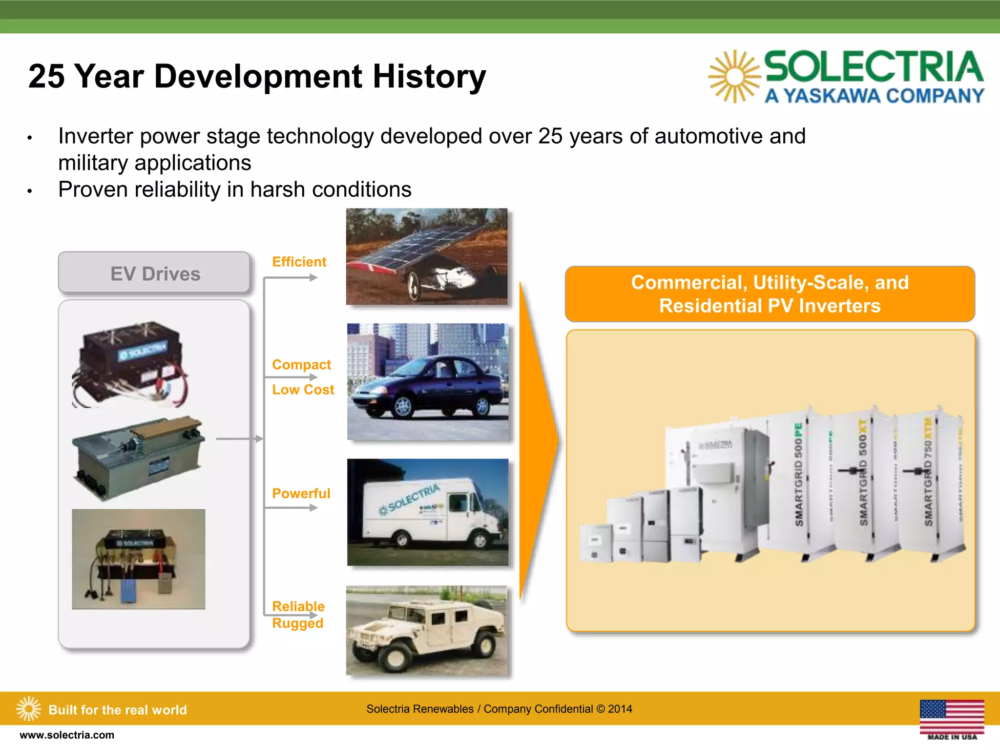
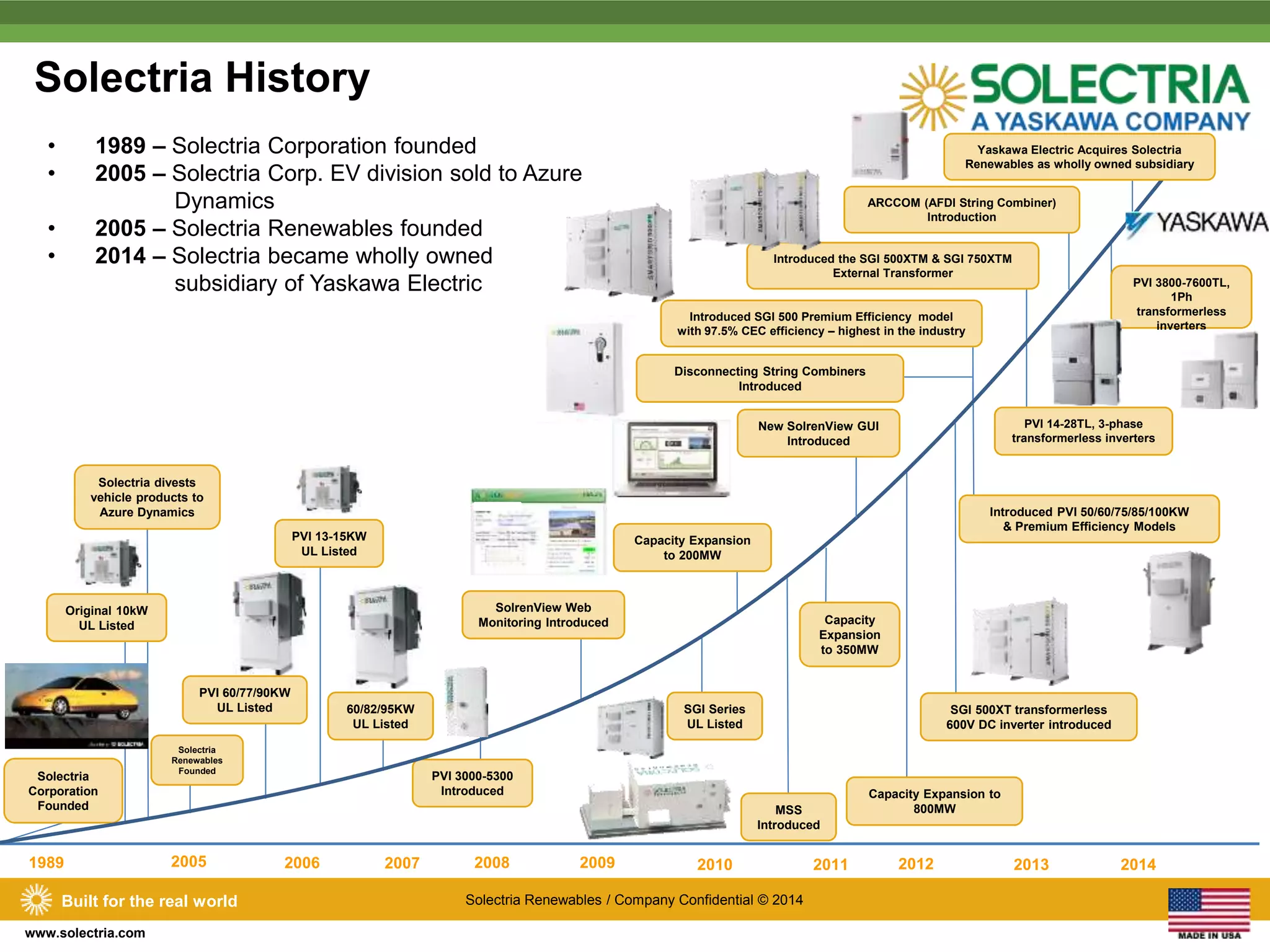
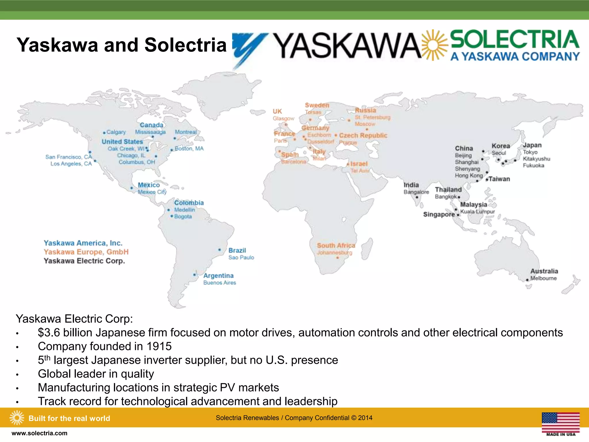
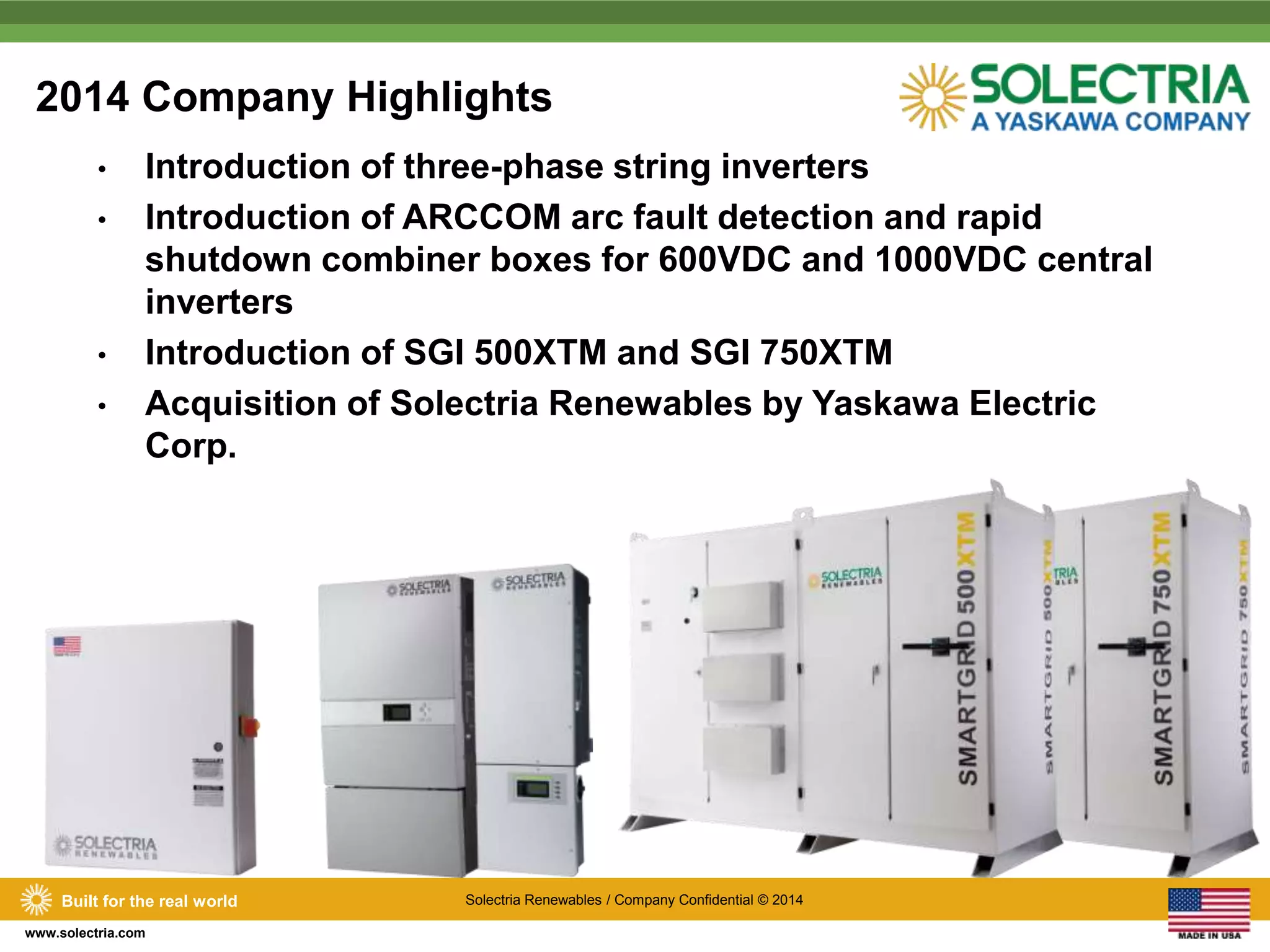

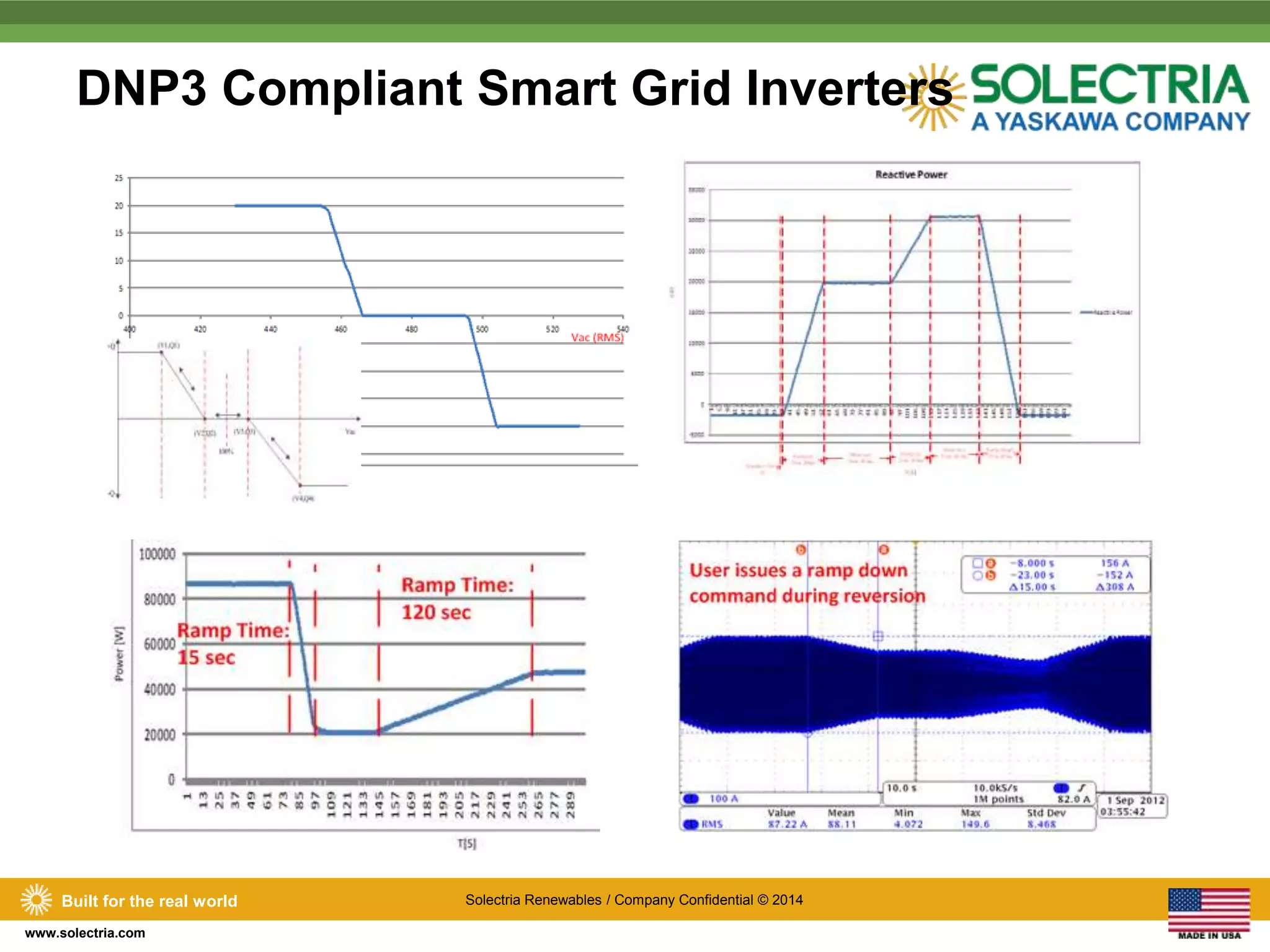

Solectria Renewables has a 25-year history of developing reliable solar inverters and related technologies, focusing on effective grounding and power management solutions for photovoltaic systems. Recently acquired by Yaskawa Electric, the company aims to enhance its market presence and product offerings while maintaining its existing team and manufacturing capabilities. Key product highlights include innovative three-phase string inverters and advancements in protective relaying and reactive power support.


![Solar_Photovoltaic_Systems_w^0s.1[2].pptx](https://cdn.slidesharecdn.com/ss_thumbnails/solarphotovoltaicsystemsw0s-250410204146-7f6b85db-thumbnail.jpg?width=640&height=640&fit=bounds)


