Performance Evolution of LTE Cellular Technology
•
0 likes•27 views

https://www.irjet.net/archives/V4/i6/IRJET-V4I6348.pdf

Recommended
Recommended
More Related Content
What's hot
What's hot (19)
Similar to Performance Evolution of LTE Cellular Technology
Similar to Performance Evolution of LTE Cellular Technology (20)
More from IRJET Journal
More from IRJET Journal (20)
Recently uploaded
Recently uploaded (20)
Performance Evolution of LTE Cellular Technology
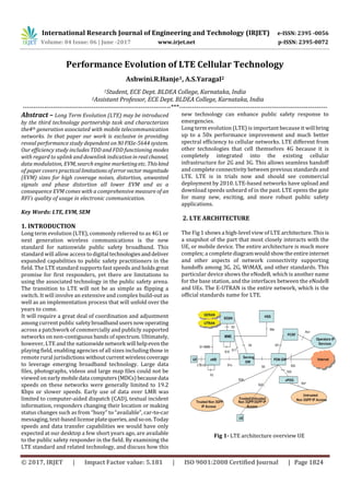
- 1. International Research Journal of Engineering and Technology (IRJET) e-ISSN: 2395 -0056 Volume: 04 Issue: 06 | June -2017 www.irjet.net p-ISSN: 2395-0072 © 2017, IRJET | Impact Factor value: 5.181 | ISO 9001:2008 Certified Journal | Page 1824 Performance Evolution of LTE Cellular Technology Ashwini.R.Hanje1, A.S.Yaragal2 1Student, ECE Dept. BLDEA College, Karnataka, India 2Assistant Professor, ECE Dept. BLDEA College, Karnataka, India ---------------------------------------------------------------------***--------------------------------------------------------------------- Abstract – Long Term Evolution (LTE) may be introduced by the third technology partnership task and characterizes the4th generation associated with mobile telecommunication networks. In that paper our work is exclusive in providing reveal performance study dependent on NI PXIe-5644 system. Our efficiency study includes TDD and FDD functioning modes with regard to uplink and downlink indication inrealchannel, data modulation, EVM, search engine marketingetc. Thiskind of paper covers practicallimitationsoferrorvector magnitude (EVM) sizes for high coverage noises, distortion, unwanted signals and phase distortion all lower EVM and as a consequence EVM comes with a comprehensive measure of an RFI’s quality of usage in electronic communication. Key Words: LTE, EVM, SEM 1. INTRODUCTION Long term evolution (LTE), commonly referred to as 4G1 or next generation wireless communications is the new standard for nationwide public safety broadband. This standard will allow access to digital technologiesanddeliver expanded capabilities to public safety practitioners in the field. The LTE standard supports fast speeds and holdsgreat promise for first responders, yet there are limitations to using the associated technology in the public safety arena. The transition to LTE will not be as simple as flipping a switch. It will involve an extensive and complex build-out as well as an implementation process that will unfold over the years to come. It will require a great deal of coordination and adjustment among current public safetybroadbandusersnowoperating across a patchwork of commercially and publicly supported networks on non-contiguous bands of spectrum. Ultimately, however, LTE and the nationwidenetwork will helpeven the playing field, enabling agencies of all sizes including those in remote rural jurisdictionswithoutcurrent wirelesscoverage to leverage emerging broadband technology. Large data files, photographs, videos and large map files could not be viewed on earlymobiledata computers(MDCs)because data speeds on these networks were generally limited to 19.2 Kbps or slower speeds. Early use of data over LMR was limited to computer-aided dispatch (CAD), textual incident information, responders changing their location or making status changes such as from “busy” to “available”, car-to-car messaging, text-based licenseplatequeries,andsoon.Today speeds and data transfer capabilities we would have only expected at our desktop a few short years ago, are available to the public safety responder in the field. By examining the LTE standard and related technology, and discuss how this new technology can enhance public safety response to emergencies. Long term evolution (LTE) is important because it will bring up to a 50x performance improvement and much better spectral efficiency to cellular networks. LTE different from other technologies that cell themselves 4G because it is completely integrated into the existing cellular infrastructure for 2G and 3G. This allows seamless handoff and complete connectivity between previous standards and LTE. LTE is in trials now and should see commercial deployment by 2010. LTE-based networks have upload and download speeds unheard of in the past. LTE opens the gate for many new, exciting, and more robust public safety applications. 2. LTE ARCHITECTURE The Fig 1 shows a high-level view of LTE architecture.Thisis a snapshot of the part that most closely interacts with the UE, or mobile device. The entire architecture is much more complex; a complete diagramwouldshowtheentireinternet and other aspects of network connectivity supporting handoffs among 3G, 2G, WiMAX, and other standards. This particular device shows the eNodeB, which is another name for the base station, and the interfaces between the eNodeB and UEs. The E-UTRAN is the entire network, which is the official standards name for LTE. Fig 1- LTE architecture overview UE
- 2. International Research Journal of Engineering and Technology (IRJET) e-ISSN: 2395 -0056 Volume: 04 Issue: 06 | June -2017 www.irjet.net p-ISSN: 2395-0072 © 2017, IRJET | Impact Factor value: 5.181 | ISO 9001:2008 Certified Journal | Page 1825 2.1 How the MAC sees the PHY The LTE PHY is the typically full duplex. LTE is designed primarily for full duplex operation in paired spectrum. To contrast, WiMAX operates in half duplex in unpaired spectrum, where information is transmitted inonedirection at a time. LTE can support TDD operation in unpaired spectrum; however; it is not a primary focus of the design. The downlink channel operates as a continuous stream.LTE uses the concept of a resource block, which is a block of 12 subcarriers in one slot. A transport block is a group of resource blocks with a common modulation/coding. The physical interface is a transport block, which corresponds to the data carried in a period of time of the allocation for the particular UE. Each radio sub frame is 1 milliseconds (ms) long; each frameis 10 milliseconds, multiple UEs can be serviced on the downlink at any particular time in one transport block. The MAC controls what to send in a given time. The LTE standard specifies these physical channels: 1) Physical broadcast channel (PBCH): The coded BCH transport block is mapped to four sub frames within a 40 ms timing, each sub frame is assumed to be self-decodable, i.e. the BCH can be decoded from a single reception, assuming sufficiently good channel conditions. 2) Physical control format indicator channel (PCFICH): It informs the UE about the number of OFDM symbols used for the PDCCHs. Transmitted in every sub frame. 3) Physical downlink control channel (PDCCH): Informs the UE about the resource allocation of PCH and DL-SCH, and hybrid ARQ information related toDL-SCHcarriestheuplink scheduling grant. 4) Physical hybrid ARQ indicator channel (PHICH): Carries hybrid ARQ ACK/NAKs in response to uplink transmissions. 5) Physical downlink shared channel (PDSCH): It carries the DL-SCH and PCH. 6) Physical multicast channel (PMCH): It carries the MCH. 7) Physical uplink control channel (PUCCH): It carries the hybrid ARQ ACK/NAKs in response to downlink transmission. It carries scheduling request (SR). It also carries CQI reports. 8) Physical uplink shared channel (PUSCH): Carries the UL- SCH. 9) Physical random access channel (PRACH): Carries the random access preamble. 2.2 Advantages of LTE Application such as automated license plate recognition (LPR) systems and GPS-enabled navigation systems will providereal timenotificationsandalerts,includingemerging Hazards and geographically specific be-on the look-out (BOLO) transmissions, all contributing to improvements in Officer and civilian safety. With LTE and the nationwide networks, first responderswillgainaccesstoinnovativetools to assist them with their critical missions. They will be in a better position to take advantages of fast changing digital technology. LTE will revolutionize the way public safety responds to emergencies. Fig 1 illustrates how data speeds are enhanced through LTE technology.LTEhasbeenadopted as a global standard because; it increases the capacity and speed of wireless data networks. 3. METHDOLOGY/PLANNING OF WORK Step: 1 Start the algorithm. Step: 2 Use long term evolution (LTE) Step: 3 Apply power selection and modulation method. Step: 4 Analysis of quality of channels Step: 5 Improvement done by changing parameters Step: 6 Final results need to be Step: 7 Stop the algorithm. Fig 2- Flow chart Long term evolution (LTE) START Power selection and modulation selection Analysis of quality of channels Improvement done by changing parameters STOP Final results need to be analyzed
- 3. International Research Journal of Engineering and Technology (IRJET) e-ISSN: 2395 -0056 Volume: 04 Issue: 06 | June -2017 www.irjet.net p-ISSN: 2395-0072 © 2017, IRJET | Impact Factor value: 5.181 | ISO 9001:2008 Certified Journal | Page 1826 4. RESULT ANALYSIS The error vector magnitude or EVM is a measure used to quantify the performance of a digital radio transmitter or receiver. Fig 3- Error vector magnitude (EVM) A signal sent by an ideal transmitter or received byareceiver would have all constellation points preciously at the ideal locations, however various imperfection in the implementations (such as carrier leakage, low image rejectionratio,phasenoiseetc.)causetheactualconstellation points to deviate from the ideal locations. Informally, EVM is a measure of how far the points are from the ideal locations. Noise, distortion, spurious signals, and phase noise all degrade EVM, and therefore EVM provides a comprehensive Measureof the quality of the radio receiverortransmitterfor use in digital communications. Transmitter EVM can be measured by specialized equipment, which demodulates the received signal in a similar way to how a real radio demodulator does it. One of the stages inatypicalphase-shift keying demodulation process produces stream of I-Q points which can be used as a reasonably reliable estimate for the ideal transmitted signal in EVM calculation, error vector magnitude (EVM) is a measurement of modulator or demodulator performance in the presence of impairments. Essentially, EVM is the vector difference at a given time between the ideal (transmitted) signal and the measured (received) signal. If used correctly, these measurements can help in identifying sources of signal degradation, such as: phase noise, I-Q imbalance,amplitudenon-linearityandfilter distortion. These types of measurements are useful for determining system performance in communications applications. For example, determining if an EDGE system conforms to the 3GPP radio transmission standards requires accurate RMS, EVM, Peak EVM, and 95th percentile for the EVM measurements. Fig 4- Error vector magnitude 5. CONCLUSIONS AND FUTURE WORK Excellent of services allows unique application in order to generally fulfill different need. To determine the efficiencyof LTE unique parameters engaged on package are EVM, modulation strategies, ACP, channel power high to high ratio etc. and LTE technique modulation plans QPSK, PSK, BPSK, etc. attribute to the simulation often aren’t similar to the partial implantations. By appraise the performance of practical implementation using unique quality of service instruction and appraise the performance of LTE technique using modulation plan BPSK, QPSK, 16 PSK etc. In preceding research your bandwidth of new crossbreed frequency is superior or SFR. There must raise your bandwidth in order that there have to be lesser supply loss. By appraise the performance of downlinkrelatingtobandwidthandalsodata free. The analysis of performance with the LTE with WiMAX is completed on your PXIE packages. As the foundation is common plus economical, it’ll soon benecessaryforpractical implementation. Various parameters have demonstratedthe effectiveness of the LTEsystems.Inforeseeablefuturewecan consider some more modulations techniques so as to evaluatethe effectivenessoftheofferedtechniqueadditional. Also limited variety of quality parameters are thought therefore in not too distant future some a lot more quality
- 4. International Research Journal of Engineering and Technology (IRJET) e-ISSN: 2395 -0056 Volume: 04 Issue: 06 | June -2017 www.irjet.net p-ISSN: 2395-0072 © 2017, IRJET | Impact Factor value: 5.181 | ISO 9001:2008 Certified Journal | Page 1827 parameters will likely be considered with regard to better assessment. REFERENCES [1] Sahoo, 2011"Performance Comparison of Packet Scheduling Algorithms for Video Traffic in LTE Cellular Network", IJMNCT, Vol.3, No.3, pp 1307. [2] A. Alfayly, I.H Mkwawa, L.Sun and Emmanuel, 2012"QoE- based PerformanceEvaluationofSchedulingAlgorithmsover LTE", IEEE, Vol8, No.4, pp 1362-1366. [3] W. Nie, H.Wang, J.Hyuk Park, 2011 " Packet Scheduling with QoS and reasonableness for downlink movement in WiMAX systems" , Journal of data preparing framework , Vol.7, No.2, pp 103-112. [4] O.Iosif, I. Banica, 2013 "Execution Analysis of Downlink LTE utilizing Systemlevel Simulator" ,U.P.B.Sci.Bull.,SeriesC, Vol.75, Iss 1, pp 815-820. [5] A.Biernacki, K.Tutschku, 2013 "Relative Performance Study of LTEDownlinkSchedulers",Springer,Vol.74,No.2,pp 585-599. [6] B.Lui, H.Tang, L.Xu , 2013" An Efficient Downlink Packet Scheduling Algorithm for Real Time TrafficsinLTESystems", IEEE CCNC, Vol.44, No.3, pp 1-5. [7] H. Al-Jaradat, K. Sandrasegaran, 2013 "On the Performance of PF, MLWDF andEXP/PFcalculationsinLTE", IJCT, Vol8, No.1, pp 132-142. [8] A. S. Sravani, K. Jagadeesh Babu, 2012 "Execution of Scheduling AlgorithmforLTEdownlink",ISSN,Vol.2,Issue-6, pp 52-59. [9] T.AYahiya, 2011 "Execution Study of Opportunistic Scheduling in LTE Networks", Springer Science, Vol.44, No.6, pp 167-180. [10] D.Keke, W.bin, G.Hui, W.Wennai, 2013 "Vitality sparing planningfortheLTEMulticastadministrations",JOURNALOF ELECTRONICS (CHINA), Vol.30, No.5, pp 423-429.