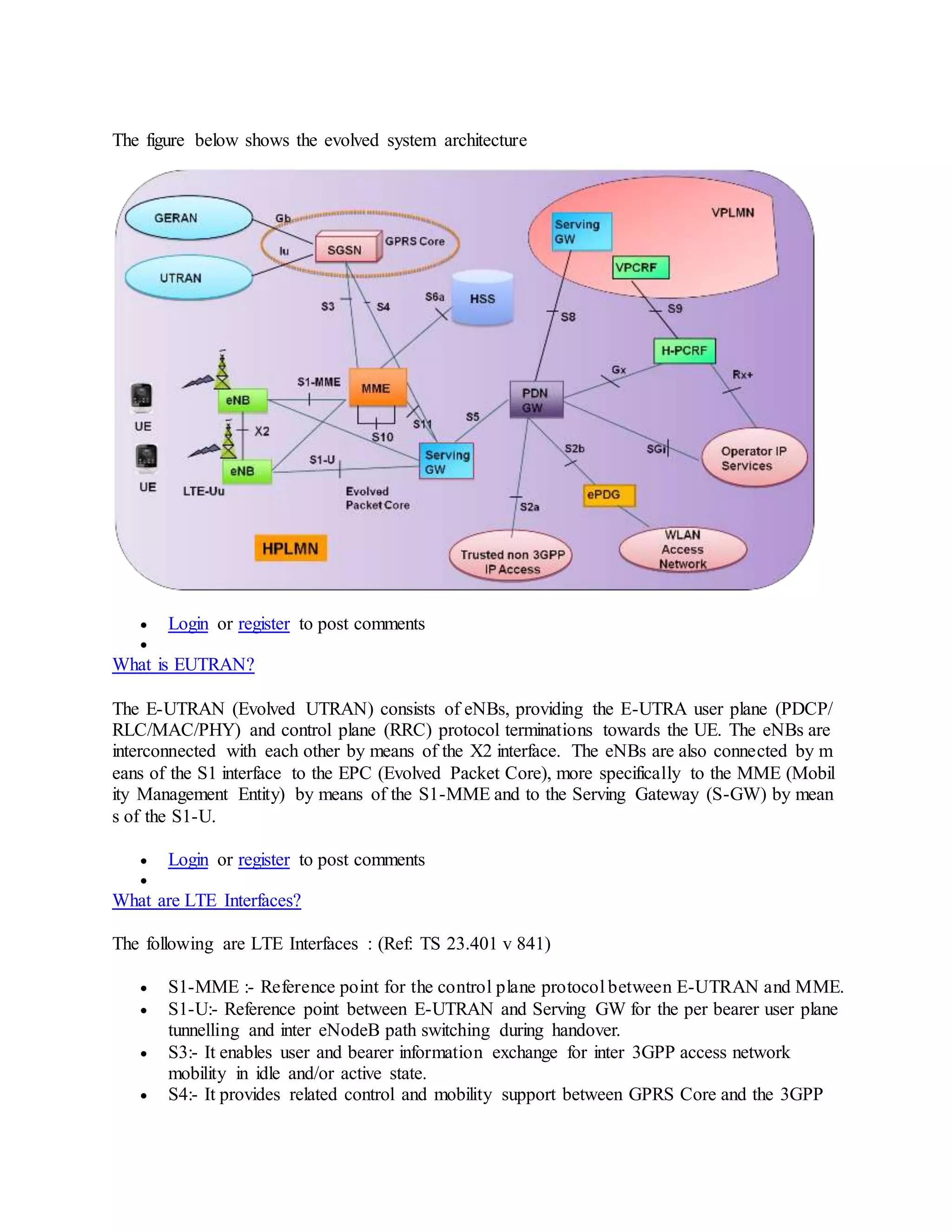
SlideShare a Scribd company logo
1 of 28
SECTION A
What is LTE?
LTEi (Long Term Evolution) is initiated by 3GPPi to improve the mobile phone standard to cope
with future technology evolutions and needs.
 Login or register to post comments

What is goal of LTE?
The goals for LTE include improving spectral efficiency, lowering costs, improving services, ma
king use of new spectrum and reformed spectrum opportunities, and better integration with other
open standards.
 Login or register to post comments

What speed LTE offers?
LTE provides downlink peak rates of at least 100Mbit/s, 50 Mbit/s in the uplink and RAN (Radi
o Access Network) round-trip times of less than 10 ms.
 Login or register to post comments

What is LTE Advanced?
LTE standards are in matured state now with release 8 frozen. While LTE Advanced is still unde
r works. Often the LTE standard is seen as 4G standard which is not true. 3.9G is more acceptabl
e for LTE. So why it is not 4G? Answer is quite simple - LTE does not fulfill all requirements of
ITU 4G definition.
Brief History of LTE Advanced: The ITU has introduced the term IMT Advanced to identify mo
bile systems whose capabilities go beyond those of IMT 2000. The IMT Advanced systems shall
provide best-in-class performance attributes such as peak and sustained data rates and correspond
ing spectral efficiencies, capacity, latency, overall network complexity and quality-of-service ma
nagement. The new capabilities of these IMT-Advanced systems are envisaged to handle a wide
range of supported data rates with target peak data rates of up to approximately 100 Mbit/s for hi
gh mobility and up to approximately 1 Gbit/s for low mobility.
See LTE Advanced: Evolution of LTE for more details.
 Login or register to post comments

What is LTE architecture?
The evolved architecture comprises E-UTRAN (Evolved UTRAN) on the access side and EPC (
Evolved Packet Core) on the core side.
The figure below shows the evolved system architecture
 Login or register to post comments

What is EUTRAN?
The E-UTRAN (Evolved UTRAN) consists of eNBs, providing the E-UTRA user plane (PDCP/
RLC/MAC/PHY) and control plane (RRC) protocol terminations towards the UE. The eNBs are
interconnected with each other by means of the X2 interface. The eNBs are also connected by m
eans of the S1 interface to the EPC (Evolved Packet Core), more specifically to the MME (Mobil
ity Management Entity) by means of the S1-MME and to the Serving Gateway (S-GW) by mean
s of the S1-U.
 Login or register to post comments

What are LTE Interfaces?
The following are LTE Interfaces : (Ref: TS 23.401 v 841)
 S1-MME :- Reference point for the control plane protocol between E-UTRAN and MME.
 S1-U:- Reference point between E-UTRAN and Serving GW for the per bearer user plane
tunnelling and inter eNodeB path switching during handover.
 S3:- It enables user and bearer information exchange for inter 3GPP access network
mobility in idle and/or active state.
 S4:- It provides related control and mobility support between GPRS Core and the 3GPP
Anchor function of Serving GW. In addition, if Direct Tunnel is not established, it
provides the user plane tunnelling.
 S5:- It provides user plane tunnelling and tunnel management between Serving GW and
PDN GW. It is used for Serving GW relocation due to UE mobility and if the Serving
GW needs to connect to a non-collocated PDN GW for the required PDN connectivity.
 S6a:- It enables transfer of subscription and authentication data for
authenticating/authorizing user access to the evolved system (AAA interface) between
MME and HSS.
 Gx:- It provides transfer of (QoS) policy and charging rules from PCRF to Policy and
Charging Enforcement Function (PCEF) in the PDN GW.
 S8:- Inter-PLMN reference point providing user and control plane between the Serving
GW in the VPLMN and the PDN GW in the HPLMN. S8 is the inter PLMN variant of S5.
 S9:- It provides transfer of (QoS) policy and charging control information between the
Home PCRF and the Visited PCRF in order to support local breakout function.
 S10:- Reference point between MMEs for MME relocation and MME to MME
information transfer.
 S11:- Reference point between MME and Serving GW.
 S12:- Reference point between UTRAN and Serving GW for user plane tunnelling when
Direct Tunnel is established. It is based on the Iu-u/Gn-u reference point using the GTP-
U protocol as defined between SGSN and UTRAN or respectively between SGSN and
GGSN. Usage of S12 is an operator configuration option.
 S13:- It enables UE identity check procedure between MME and EIR.
 SGi:- It is the reference point between the PDN GW and the packet data network. Packet
data network may be an operator external public or private packet data network or an
intra operator packet data network, e.g. for provision of IMS services. This reference
point corresponds to Gi for 3GPP accesses.
 Rx:- The Rx reference point resides between the AF and the PCRF in the TS 23.203.
 SBc:- Reference point between CBC and MME for warning message delivery and control
functions.
 Login or register to post comments

What are LTE Network elements?
eNB
eNB interfaces with the UE and hosts the PHYsical (PHY), Medium Access
Control (MAC), Radio Link Control (RLC), and Packet Data Control
Protocol (PDCP) layers. It also hosts Radio Resource Control (RRC)
functionality corresponding to the control plane. It performs many
functions including radio resource management, admission control,
scheduling, enforcement of negotiated UL QoS, cell information
broadcast, ciphering/deciphering of user and control plane data, and
compression/decompression of DL/UL user plane packet headers.
Mobility Management Entity
manages and stores UE context (for idle state: UE/user identities, UE mobility state, user security
parameters). It generates temporary identities and allocates them to UEs. It checks the authorizat
ion whether the UE may camp on the TA or on the PLMN. It also authenticates the user.
Serving Gateway
The SGW routes and forwards user data packets, while also acting as the mobility anchor for the
user plane during inter-eNB handovers and as the anchor for mobility between LTE and other 3G
PP technologies (terminating S4 interface and relaying the traffic between 2G/3G systems and P
DN GW).
Packet Data Network Gateway
The PDN GW provides connectivity to the UE to external packet data networks by being the poi
nt of exit and entry of traffic for the UE. A UE may have simultaneous connectivity with more th
an one PDN GW for accessing multiple PDNs. The PDN GW performs policy enforcement, pack
et filtering for each user, charging support, lawful Interception
and packet screening.
 Login or register to post comments

What are LTE protocols & specifications?
In LTE architecture, core network includes Mobility Management Entity (MME), Serving Gatew
ay (SGW), Packet Data Network Gateway (PDN GW) where as E-UTRAN has E-UTRAN Nod
eB (eNB).
See LTE protocols & specifications for specification mappings.
Protocol links are as below
 Air Interface Physical Layer
 GPRS Tunnelling Protocol User Plane (GTP-U)
 GTP-U Transport
 Medium Access Control (MAC)
 Non-Access-Stratum (NAS) Protocol
 Packet Data Convergence Protocol (PDCP)
 Radio Link Control (RLC)
 Radio Resource Control (RRC)
 S1 Application Protocol (S1AP)
 S1 layer 1
 S1 Signalling Transport
 X2 Application Protocol (X2AP)
 X2 layer 1
 X2 Signalling Transport
 Login or register to post comments

What is VoLGA?
VoLGA stands for "Voice over LTE via Generic Access". The VoLGA service resembles the 3G
PP Generic Access Network (GAN). GAN provides a controller node - the GAN controller (GA
NC) - inserted between the IP access network (i.e., the EPS) and the 3GPP core network.
The GAN provides an overlay access between the terminal and the CS core without requiring spe
cific enhancements or support in the network it traverses. This provides a terminal with a 'virtual'
connection to the core network already deployed by an operator. The terminal and network thus
reuse most of the existing mechanisms, deployment and operational aspects.
see VoLGA - Voice over LTE via Generic Access for more details.
 Login or register to post comments

What is CS Fallback in LTE?
LTE technology supports packet based services only, however 3GPP does specifies fallback for c
ircuit switched services as well. To achieve this LTE architecture and network nodes require addi
tional functionality, this blog is an attempt to provide overview for same.
In LTE architecture, the circuit switched (CS) fallback in EPS enables the provisioning of voice
and traditional CS-domain services (e.g. CS UDI video/ SMS/ LCS/ USSD). To provide these se
rvices LTE reuses CS infrastructure when the UE is served by E UTRAN.
See Understanding CS Fallback in LTE for more details.
 Login or register to post comments

How does LTE Security works?
The following are some of the principles of 3GPP E-UTRAN security based on 3GPP Release 8
specifications:
 The keys used for NAS and AS protection shall be dependent on the algorithm with
which they are used.
 The eNB keys are cryptographically separated from the EPC keys used for NAS
protection (making it impossible to use the eNB key to figure out an EPC key).
 The AS (RRC and UP) and NAS keys are derived in the EPC/UE from key material that
was generated by a NAS (EPC/UE) level AKA procedure (KASME) and identified with a
key identifier (KSIASME).
 The eNB key (KeNB) is sent from the EPC to the eNB when the UE is entering ECM-
CONNECTED state (i.e. during RRC connection or S1 context setup).
See LTE Security Principles for more details.
 Login or register to post comments

What is IP Multimedia Subsystem (IMS)?
The 3GPP IP Multimedia Subsystem (IMS) technology provides an architectural framework for
delivering IP based multimedia services. IMS enables telecom service providers to offer a new g
eneration of rich multimedia services across both circuit switched and packet switched networks.
IMS offers access to IP based services independent of the access network e.g. wireless access (G
PRS, 3GPP’s UMTS, LTE, 3GPP2’s CDMA2000) and fixed networks (TISPAN’s NGN)
IMS defines a architecture of logical elements using SIP for call signaling between network elem
ents and Provides a layered approach with defined service, control, and transport planes. Some of
IMS high level requirements are noted below:
The application plane provides an infrastructure for the provision and management of services, s
ubscriber configuration and identity management and defines standard interfaces to common fun
ctionality.
The IMS control plane handles the call related signaling and controls transport plane. Major elem
ent of control plane is the Call Session Control Function (CSCF) , which comprises Proxy-CSCF
(P-CSCF), Interrogating-CSCF (I-CSCF) and Serving-CSCF (S-CSCF). The CSCF (Call/Sessio
n Control Function) is essentially a SIP server.
The IMS transport plane provides a core IP network with access from subscriber device over wir
eless or wireline networks.
 Login or register to post comments

How does measurements work in LTE?
In LTE E-UTRAN measurements to be performed by a UE for mobility are classified as below
 Intra-frequency E-UTRAN measurements
 Inter-frequency E-UTRAN measurements
 Inter-RAT measurements for UTRAN and GERAN
 Inter-RAT measurements of CDMA2000 HRPD or 1xRTT frequencies
See Measurements in LTE E-UTRAN for details.
 Login or register to post comments

What is Automatic Neighbour Relation?
According to 3GPP specifications, the purpose of the Automatic Neighbour Relation (ANR) func
tionality is to relieve the operator from the burden of manually managing Neighbor Relations (N
Rs). This feature would operators effort to provision.
Read Automatic Neighbour Relation in LTE for more details.
 Login or register to post comments

How does Intra E-UTRAN Handover is performed?
Intra E-UTRAN Handover is used to hand over a UE from a source eNodeB to a target eNodeB
using X2 when the MME is unchanged. In the scenario described here Serving GW is also uncha
nged. The presence of IP connectivity between the Serving GW and the source eNodeB, as well
as between the Serving GW and the target eNodeB is assumed.
The intra E-UTRAN HO in RRC_CONNECTED state is UE assisted NW controlled HO, with H
O preparation signalling in E-UTRAN.
Read LTE Handovers - Intra E-UTRAN Handover for more details.
 Login or register to post comments

How does policy control and charging works in LTE?
A important component in LTE network is the policy and charging control (PCC) function that b
rings together and enhances capabilities from earlier 3GPP releases to deliver dynamic control of
policy and charging on a per subscriber and per IP flow basis.
LTE Evolved Packet Core (EPC) EPC includes a PCC architecture that provides support for fine-
grained QoS and enables application servers to dynamically control the QoS and charging requir
ements of the services they deliver. It also provides improved support for roaming. Dynamic cont
rol over QoS and
charging will help operators monetize their LTE investment by providing customers with a varie
ty of QoS and charging options when choosing a service.
The LTE PCC functions include:
 PCRF (policy and charging rules function) provides policy control and flow based
charging control decisions.
 PCEF (policy and charging enforcement function) implemented in the serving gateway,
this enforces gating and QoS for individual IP flows on the behalf of
 the PCRF. It also provides usage measurement to support charging
 OCS (online charging system) provides credit management and grants credit to the PCEF
based on time, traffic volume or chargeable events.
 OFCS (off-line charging system) receives events from the PCEF and generates charging
data records (CDRs) for the billing system.
Refer following whitepapers for more details.
Introduction to Evolved Packet Core
Policy control and charging for LTE networks
Quality of Service (QoS) and Policy Management in Mobile Data Networks
 Login or register to post comments

What is SON & how does it work in LTE?
Self-configuring, self-optimizing wireless networks is not a new concept but as the mobile netwo
rks are evolving towards 4G LTE networks, introduction of self configuring and self optimizing
mechanisms is needed to minimize operational efforts. A self optimizing function would increase
network performance and quality reacting to dynamic processes in the network.
This would minimize the life cycle cost of running a network by eliminating manual configuratio
n of equipment at the time of deployment, right through to dynamically optimizing radio network
performance during operation. Ultimately it will reduce the unit cost and retail price of wireless
data services.
See Self-configuring and self-optimizing Networks in LTE for details.
 Login or register to post comments

How does Network Sharing works in LTE?
3GPP network sharing architecture allows different core network operators to connect to a share
d radio access network. The operators do not only share the radio network elements, but may als
o share the radio resources themselves.
Read Network Sharing in LTE for more.
 Login or register to post comments

How does Timing Advance (TA) works in LTE?
In LTE, when UE wish to establish RRC connection with eNB, it transmits a Random Access Pr
eamble, eNB estimates the transmission timing of the terminal based on this. Now eNB transmits
a Random Access Response which consists of timing advance command, based on that UE adjus
ts the terminal transmit timing.
The timing advance is initiated from E-UTRAN with MAC message that implies and adjustment
of the timing advance.
See Timing Advance (TA) in LTE for further details.
 Login or register to post comments

How does LTE UE positioning works in E-UTRAN?
UE Positioning function is required to provide the mechanisms to support or assist the calculatio
n of the geographical position of a UE. UE position knowledge can be used, for example, in supp
ort of Radio Resource Management functions, as well as location-based services for operators, su
bscribers, and third-party service providers.
See LTE UE positioning in E-UTRAN for more details.
 Login or register to post comments

How many operators have committed for LTE?
List of operators committed for LTE has been compiled by 3GAmericas from Informa Telecoms
& Media and public announcements. It includes a variety of commitment levels including intenti
ons to trial, deploy, migrate, etc.
For latest info visit http://ltemaps.org/
 Login or register to post comments

What is Single Radio Voice Call Continuity (SRVCC)?
Along with LTE introduction, 3GPP also standardized Single Radio Voice Call Continuity (SRV
CC) in Release 8 specifications to provide seamless continuity when an UE handovers from LTE
coverage (E-UTRAN) to UMTS/GSM coverage (UTRAN/GERAN). With SRVCC, calls are an
chored in IMS network while UE is capable of transmitting/receiving on only one of those access
networks at a given time.
See Evolution of Single Radio Voice Call Continuity (SRVCC) for more details.
 Login or register to post comments

How does Location Service (LCS) work in LTE network?
In the LCS architecture, an Evolved SMLC is directly attached to the MME. The objectives of th
is evolution is to support location of an IMS emergency call, avoid impacts to a location session
due to an inter-eNodeB handover, make use of an Evolved and support Mobile originated locati
on request (MO-LR) and mobile terminated location request MT-LR services.
Release 9 LCS solution introduces new interfaces in the EPC:
 SLg between the GMLC and the MME
 SLs between the E-SMLC and the MME
 Diameter-based SLh between the HSS and the HGMLC
For details read LCS Architecture for LTE EPS and LTE UE positioning in E-UTRAN
 Login or register to post comments

How does Lawful Interception works in LTE Evolved Packet System?
3GPP Evolved Packet System (EPS) provides IP based services. Hence, EPS is responsible only
for IP layer interception of Content of Communication (CC) data. In addition to CC data, the La
wful Interception (LI) solution for EPS offers generation of Intercept Related Information (IRI) r
ecords from respective control plane (signalling) messages as well.
See Lawful Interception Architecture for LTE Evolved Packet System for more details.
 Login or register to post comments

What is carrier aggregation in LTE-Advanced?
To meet LTE-Advanced requirements, support of wider transmission bandwidths is required than
the 20 MHz bandwidth specified in 3GPP Release 8/9. The preferred solution to this is carrier ag
gregation.
It is of the most distinct features of 4G LTE-Advanced. Carrier aggregation allows expansion of
effective bandwidth delivered to a user terminal through concurrent utilization of radio resources
across multiple carriers. Multiple component carriers are aggregated to form a larger overall tran
smission bandwidth.
See Carrier Aggregation for LTE-Advanced for more details.
 Login or register to post comments

What is Relay Node and how does Relaying works in LTE-Advanced?
For efficient heterogeneous network planning, 3GPP LTE-Advanced has introduced concept of
Relay Nodes (RNs). The Relay Nodes are low power eNodeBs that provide enhanced coverage a
nd capacity at cell edges. One of the main benefits of relaying is to provide extended LTE cover
age in targeted areas at low cost.
The Relay Node is connected to the Donor eNB (DeNB) via radio interface, Un, a modified versi
on of E-UTRAN air interface Uu. Donor eNB also srves its own UE as usual, in addition to shari
ng its radio resources for Relay Nodes.
SECTION B
1
.
Which type of cell provides the best level of service for average subscribers?
A. Acceptable cell
B. Barred Cell
C. Reserved Cell
D. Suitable Cell
2
.
Why is a Cyclic Prefix required in OFDMA?
A. The Metropolitan museum of art
B. Boston Smithsonian
C. NASA
D. Washington Smithsonian institution museum of fine art
3
.
Which UE categories support 64QAM on the uplink?
A. Only category 5
B. Categories 3, 4 and 5
C. None of them
D. All of them
4
.
What types of handover are supported in LTE?
A. Hard handover only
B. Hard and soft handovers
C. Hard, soft and softer handovers
D. Handover is not supported
5
.
What does the DC subcarrier indicate?
A. The identity of the cell
B. The antenna configuration
C. The center of the OFDM channel
D. The format of the data channel
6
.
What processing step combines multiple OFDM subcarriers into a single signal for transmissio
n?
A. FFT
B. IFFT
C. RF Combining
D. Channel Mapping
7
.
What is the minimum amount of RF spectrum needed for an FDD LTE radio channel?
A. 1.4 MHz
B. 2.8 MHz
C. 5 MHz
D. 20 MHz
8
.
In MIMO, which factor has the greatest influence on data rates?
A. The size of the antenna
B. The height of the antenna
C. The number of transmit antennas
D. The number of receive antennas
9
.
What organization is responsible for developing LTE standards?
A. UMTS
B. 3GPP
C. 3GPP2
D. ISO
10
.
Which channel indicates the number of symbols used by the PDCCH?
A. PHICH
B. PDCCH
C. PBCH
D. PCFICH
11
.
How often can resources be allocated to a UE?
A. Every symbol
B. Every slot
C. Every subframe
D. Every frame
12
.
What property of OFDMA systems allows adjacent subcarriers to be used without interferenc
e?
A. Orthogonality
B. Orthodoxy
C. Octagonality
D. Originality
13
.
With the normal Cyclic Prefix, how many symbols are contained in 1 frame?
A. 7
B. 12
C. 20
D. 140
14
.
What is the largest channel bandwidth a UE is required to support in LTE?
A. 20 MHz
B. 10 MHz
C. 5 MHz
D. 1.4 MHz
15
.
In OFDM, what is the relationship between the subcarrier spacing f and the symbol time t?
A. There is no fixed relation
B. f = t
C. f x t = 2048
D. f = 1/t
16
.
What is the PBCH scrambled with?
A. The physical cell ID
B. The current frame number
C. The UE's C-RNTI
D. The PBCH is not scrambled
17
.
Why is the Cyclic Prefix a copy of the tail end of the symbol?
A. It ensures a continuous time domain signal
B. It maintains an integer number of cycles
C. It reduces the Peak-to-Average Power Ratio (PAPR)
D. It increases the useful symbol time
18
.
In LTE, what is the benefit of PAPR reduction in the uplink?
A. Improved uplink coverage
B. Lower UE power consumption
C. Reduced equalizer complexity
D. All of the above
19
.
Approximately what portion of a subframe in a 1.4 MHz channel is available for carrying the
PDSCH?
A. 1/2
B. 1/4
C. 3/4
D. 1/6
20
.
If the UE detects primary synchronization sequence x and secondary synchronization sequen
ce y, what is the physical cell ID?
A. The physical cell ID cannot be determined from the synchronization signals
B. x+y
C. 3x+y
D. x+3y
21
.
Which RLC mode adds the least amount of delay to user traffic?
A. Acknowledged Mode (AM)
B. Unacknowledged Mode (UM)
C. Transparent Mode (TM)
D. Low Latency Mode (LM)
22
.
What coding scheme is used for the DL-SCH and UL-SCH?
A. 1/3 tail-biting convolutional code
B. 1/3 turbo code
C. Variable-rate block code
D. 1/3 repetition code
23
.
How much bandwidth is required to transmit the primary and secondary synchronization sign
als?
A. 1.4 MHz
B. 1.08 MHz
C. 930 kHz
D. up to 20 MHz
24
.
What is the length of the shortest possible PDCCH, in bits?
A. 72
B. 144
C. 288
D. 576
25
.
With PRACH configuration 14, what are the odds that two UE's will collide during their rand
om accesses?
A. 1 in 10
B. 1 in 64
C. 1 in 640
D. It is impossible to collide on the PRACH
SECTION C
LTE and LTE advanced technology is fast evolving in cellular arena and demand in the industrie
s have been increased for LTE skilled engineers. These top 12 LTE interview questions and answ
ers help engineers seeking LTE technology job to crack the interview with ease. One can refer pa
ge links mentioned on left side panel to learn more about LTE.
Question-1: What is the difference between LTE FDD and LTE TDD?
Answer-1:The difference lies in the LTE frame structure in both the FDD and TDD versions of t
he LTE. In FDD there will be pair of frequencies assigned in the downlink and uplink directions
and hence transmissions from multiple subscribes can happen at the same time but on different fr
equencies as mentioned. In TDD, one single frequency will be used at different time instants by
multiple subscriber terminals (UEs). Both frame versions of LTE will have 1 ms sub-frame durat
ion and 0.5 ms slot duration.
Question-2: What is resource block in LTE?
Answer-2:LTE frame is divided based on time slots on time axis and frequency subcarrier on fre
quency axis. Resource block is the smallest unit of resource allocation in LTE system. It is of ab
out 0.5ms duration and composed of 12 subcarriers in 1 OFDM symbol. One time slot is equal to
7 OFDM symbols in normal cyclic prefix and 6 OFDM symbols in extended cyclic prefix. One f
ull resource block is equal to 12 subcarriers by 7 symbols in normal CP. Hence it consists of total
84 time/frequency elements referred as resource elements in LTE network. Refer LTE Terminol
ogy
.
Question-3: What are the LTE logical, transport and physical channels? Answer-3:All these chan
nels help LTE UE establish the connection with the eNodeB, maintain the connection and termin
ate the same. Logical channels are characterized by the information that is transferred. Transport
channels are characterized by how the data are transferred over the radio interface. Physical chan
nel corresponds to a set of resource elements used by the physical layer. Channels are further div
ided into control channel and traffic channel at logical channel stage. Read more.
Question-4: Explain the difference between Reference signal (RS) and synchronization signal (S
S) in the LTE? Also mention types of RS and SS.
Answer-4:Reference signal (RS) is used as pilot subcarrier in LTE similar to other broadband wir
eless technologies such as WLAN, WIMAX etc. Synchronization signal is used as preamble seq
uence in LTE for synchronization purpose. RS is used for channel estimation and tracking. SS ar
e of two types viz. P-SS and S-SS. P-SS is used for initial synchronization. S-SS is used for fram
e boundary determination. RS are of two types viz. Demodulation RS (DRS) and Sounding RS (
SRS). DRS is used for sync and channel estimation purpose. SRS is used for channel quality esti
mation purpose. DRS is used in both the uplink and downlink, while SRS is used only in the upli
nk. Refer LTE PSS SSS
and LTE RS DMRS SRS
pages to know insight concepts of synchronization signal and reference signal.
Question-5: Explain LTE cell search procedure followed by UE.
Answer-5:LTE cell search procedure is used by UE to camp onto the LTE cell i.e. eNodeB. Refe
r LTE UE cell search procedure and network entry procedure.
Question-6: What is the function of LTE physical broadcast channel i.e. PBCH?
Answer-6:After initial cell synchronization is completed, UE reads MIB (Master information blo
ck) on PBCH (Physical channel). Broadcast channel is referred as BCH at transport level and BC
CH at logical level. MIB composed of downlink channel bandwidth in units of RBs, PHICH dura
tion, PHICH resource and system frame number. Read more.
Question-7: What is the advantage of using SC-FDMA in the LTE uplink?
Answer-7:The main advantage of SC-FDMA is low PAPR compare to OFDMA used in LTE do
wnlink. This increases the efficiency of power amplifier and hence increases the battery life. Rea
d more.
Question-8: What is RSSI?
Answer-8:RSSI stands for Received Signal Strength Indication. It is used almost in all the RATs
to identify power received from the cell in idle as well as connected/dedicated modes. This helps
UE always camped on to the best cell all the time. In case of drop in power measured using RSSI
, either UE or network initiates the handover or cell re-selection is carried out. Read more.
Question-9: Explain Circuit Switch Fall Back i.e. CSFB with respect to LTE and GSM.
Answer-9:Framework allowing the provisioning of voice services by reuse of legacy GSM serve
d CS infrastructure when the UE is served by E-UTRAN (LTE).To provide voice call support, Ci
rcuit Switch Fall Back is carried out to GSM RAT from LTE RAT to facilitate the voice over LT
E (VoLTE) feature. Read more.
Question-10: Explain LTE network architecture and various interfaces.
Answer-10:There are various entities forming the LTE network architecture, the main interfaces
are Uu between UE and eNB, X2 interface between eNBs and S1 interface between eNB and EP
C(Evolved Packet Core). Read more.
Question-11: What is SRVCC?
Answer-11:SRVCC is the short form of Single-Radio Voice Call Continuity. SRVCC handover i
s supported from E-UTRAN (i.e. LTE) to UTRAN/GERAN (WCDMA/GSM). SRVCC procedur
e is used for transferring an on-going PS voice call (IMS) in LTE to a CS voice call via Handove
r from LTE to GERAN/UTRAN. Read more.
Question-12:What is the difference between LTE and LTE Advanced?
Answer-12:LTE is specified in 3GPP release 8 and release 9. LTE advanced is specified in 3GPP
release 10. The main difference between them is carrier aggregation is introduced in LTE advan
ced. Number of antennas supported by MIMO has been increased to 8 in LTE advanced,Read m
ore.
SECTION D
LTE InterviewQuestions?
1) What happens when a LTE UE is powered on? From PHY Layer Point of view & NAS Point of vi
ew?
2) Explain attach procedure in LTE?
3) Why there is two types of security in LTE?
4) What are the measurement events in LTE?
Ans:
Intra/Inter Frequency Events:
Event A1 (Serving becomes better than threshold)
Event A2 (Serving becomes worse than threshold)
Event A3 (Neighbour becomes offset better than PCell)
Event A4 (Neighbour becomes better than threshold)
Event A5 (PCell becomes worse than threshold1 and neighbour becomes better than threshold2)
Event A6 (Neighbour becomes offset better than SCell)
Inter RAT Events:
Event B1 (Inter RAT neighbour becomes better than threshold)
Event B2 (PCell becomes worse than threshold1 and inter RAT neighbour becomes better than
threshold2)
5) What is DCI?
6) What are the contents of DCI?
7) What are the main difference between DCI0 and DCI1a?
8) What is contention resolution?
9) When Radio Link Failure is detected?
Ans:
Radio link failure to be detected:
1) upon T310 expiry
2) upon random access problem indication from MAC while neither T300, T301, T304 nor T31
1 is running
3) upon indication from RLC that the maximum number of re-transmissions has been reached
10) What is SRS used for?
Ans: UL reference signal used to measure the channel quality over a section of the bandwidth.
Node B use this information for frequency selective scheduling and link adaptation decisions.
11) What is DMRS/DRS?
Ans: DMRS/DRS is uplink reference signal.
Used for : 1)Channel Estimation and synchronization in UL
2)EnodeB can use DMRS for calculating TA command for each UE.
Two Types: 1) PUSCH DMRS.
2) PUCCH DMRS.
PUSCH DMRS:
1) Included in every resource block allocated to UE for PUSCH transmission.
2) Distributed only in Frequency domain to preserve the PAPR characteristic of SC-FD
MA.
3) 12 Resource element per resource block allocated to PUSCH DMRS.
PUCCH DMRS:
1) Included in every resource block allocated to UE for PUCCH transmission(if transmit
ted).PUCCH occupies 2 resource block per 1 ms subframe when transmitted.
2) No of REs used for PUCCH DMRS depends on a) PUCCH format to be transmitted a
nd whether b) normal or extended cyclic prefix used.
3) PUCCH DRMS used more no of bits in case of format 1,1a,1b and less no of bits in cas
eof format 2, 2a, 2b.
12) What is SPS? Explain SPS?
Ans: http://howltestuffworks.blogspot.in/2013/10/semi-persistent-scheduling.html
13) What is DRX?
14) Explain Connected mode DRX and Idle mode DRX?
15) Why PHICH configuration is mentioned in MIB?
16) In what are the scenario RACH is triggered?
17) What is RACH Procedure?
18) How UE come to know which RACH Preamble to USE?
19) Why there is no SOFT HO in LTE?
20) What PLMN Selection Order UE follows during Automatic PLMN selection and Manual PLM
N Selection?
21) What is Timing Advance? What happens if Timing Advance Timer Expires?
Ans: The timing of UL radio frame is relative to DL radio frame. EnB provides timing advance co
mmand to each UEsuch that all UL transmissions arrive at the eNodeB in synchronous manner.
If TA timer expires UE goes of reestablishment procedure or move to idle.
22) What is SR? What is the use of SR?
23) What is MAC CE?
24) What is BackOff Indicator? What is the use of Backoff indicator?
Ans :
Backoff Indicator is a special MAC subheader that carries the parameter indicating the time delay
between a PRACH and the next PRACH.
if the Random Access Response contains a Backoff Indicator subheader
set the backoff parameter value in the UE as indicated by the BI field of the Backoff Indicator s
ubheader
else,
set the backoff parameter value in the UE to 0 ms.
25) What is BSR?
Ans: The Buffer Status reporting procedure is used to provide the serving eNB with informati
on about the amount of data available for transmission in the UL buffers of the UE.
26) At what scenario UE triggers BSR?
Ans:
 UL data, for a logical channel which belongs to a LCG, becomes available for
transmission in the RLC entity or in the PDCP entity and either the data belongs to a
logical channel with higher priority than the priorities of the logical channels which
belong to any LCG and for which data is already available for transmission, or there is no
data available for transmission for any of the logical channels which belong to a LCG, in
which case the BSR is referred below to as "Regular BSR";
 UL resources are allocated and number of padding bits is equal to or larger than the size
of the Buffer Status Report MAC control element plus its subheader, in which case the
BSR is referred below to as "Padding BSR"
 retxBSR-Timer expires and the UE has data available for transmission for any of the
logical channels which belong to a LCG, in which case the BSR is referred below to as
"Regular BSR"
 periodicBSR-Timer expires, in which case the BSR is referred below to as "Periodic BSR".
27) When different types of BSR are Triggered?
Ans:
For Regular and Periodic BSR:
if more than one LCG has data available for transmission in the TTI where the BSR is transmitt
ed
report Long BSR
else,
report Short BSR.
For Padding BSR:
if the number of padding bits is equal to or larger than the size of the Short BSR plus its subhead
er but smaller than the size of the Long BSR plus its subheader:
if more than one LCG has data available for transmission in the TTI where the BSR is transm
itted: report Truncated BSR of the LCG with the highest priority logical channel with data availa
ble for transmission;
else
report Short BSR.
else if the number of padding bits is equal to or larger than the size of the Long BSR plus its sub
header,
report Long BSR.
28) What is the use of system info modification period?
29) What is the content of RAR?
Ans:
A MAC RAR consists of the four fields
 R
 Timing Advance Command
 UL Grant
 Temporary C-RNTI
30) What is the USE of UE specific Reference signal?
31) What is Cell Specific Reference Signal?
32) In what are the scenario UE Triggers RRC Connection Reestablishment?
Ans:
UE Triggers RRC Connection Reestablishment procedure on following condition:
 Upon detecting Radio Link Failure
 Handover Failure
 Mobility From E-UTRA Failure
 Integrity Failure Indication Received From Lower Layers
 RRC Connection Reconfiguration Failure
33) What is GUTI?
34) What is the significance of S-TMSI?
35) What is the content of Paging Message?
36) When UE activates integrity and ciphering?
Ans:
 The SECURITY MODECOMMAND message is used to command the UE for the
activation of AS security. E-UTRAN always initiates this procedure prior to the
establishment of Signalling Radio Bearer2 (SRB2) and Data Radio Bearers (DRBs).
 AS security comprises of the integrity protection of RRC signalling (SRBs) as well as the
ciphering of RRC signalling (SRBs) and user plane data (DRBs). The integrity protection
algorithm is common for signalling radio bearers SRB1 and SRB2. The ciphering
algorithm is common for all radio bearers (i.e. SRB1, SRB2 andDRBs). Neither integrity
protection nor ciphering applies for SRB0.
 The eNodeB sends integrity protected SECURITY MODE COMMAND message to the UE.
The UE shall derive KeNB and KRRCint which is associated with integrity protection
algorithm indicated in the SECURITY MODE COMMAND. Then, UE verifies the
Integrity of the received SECURITY MODE COMMAND by checking the Message
Authentication Code (MAC) in the SECURITY MODE COMMAND message. If
the SECURITY MODECOMMANDmessage fails the integrity protection check, then the
UE sends SECURITY MODE FAILURE to the eNodeB.
 If the SECURITY MODECOMMAND passes the integrity protection check, then the UE
shall derive the encryption keys KRRCenc key and the KUPenc keys associated with the
ciphering algorithm indicated in theSECURITY MODECOMMAND.
 The UE shall apply integrity protection using the indicated algorithm (EIA) and the
integrity key, KRRCintimmediately, i.e. integrity protection shall be applied to all
subsequent messages received and sent by the UE, including the SECURITY MODE
COMPLETE message.
 The UE shall apply ciphering using the indicated algorithm (EEA), KRRCenc key and
the KUPenc key after completing the procedure, i.e. ciphering shall be applied to all
subsequent messages received and sent by the UE, except for the SECURITY MODE
COMPLETE message which is sent un-ciphered.
36) How many default and dedicated bearer possible in lte?
37) Can there be multiple default bearer to same PDN?
38) How the position of each SIB is calculated in LTE?
39) How measurement GAP calculation happens in LTE?

More Related Content

What's hot

Lte default and dedicated bearer / VoLTE
Lte default and dedicated bearer / VoLTELte default and dedicated bearer / VoLTE
Lte default and dedicated bearer / VoLTEmanish_sapra
 
Lte irat-troubleshooting-guide
Lte irat-troubleshooting-guideLte irat-troubleshooting-guide
Lte irat-troubleshooting-guideDenmark Wilson
 
422738668-LTE-Downlink-Throughput-Optimization-Based-on-Performance-Data [Rep...
422738668-LTE-Downlink-Throughput-Optimization-Based-on-Performance-Data [Rep...422738668-LTE-Downlink-Throughput-Optimization-Based-on-Performance-Data [Rep...
422738668-LTE-Downlink-Throughput-Optimization-Based-on-Performance-Data [Rep...SudheeraIndrajith
 
3 lte mac_rrc(조봉열)
3 lte mac_rrc(조봉열)3 lte mac_rrc(조봉열)
3 lte mac_rrc(조봉열)Dattaraj Pangam
 
04 umts traffic managementnew
04 umts traffic managementnew04 umts traffic managementnew
04 umts traffic managementnewsivakumar D
 
Lte capacity monitoring
Lte capacity monitoringLte capacity monitoring
Lte capacity monitoringKlajdi Husi
 
Volte troubleshooting
Volte troubleshootingVolte troubleshooting
Volte troubleshootingJamil Awan
 
LTE RADIO PROTOCOLS
LTE RADIO PROTOCOLSLTE RADIO PROTOCOLS
LTE RADIO PROTOCOLSbrkavyashree
 
Lte coverage optimization analysis
Lte coverage optimization analysisLte coverage optimization analysis
Lte coverage optimization analysisArnoldus Leo Karra
 
5 g ran architcture
5 g ran architcture5 g ran architcture
5 g ran architctureHemraj Kumar
 
LTE KPIs and Formulae
LTE KPIs and FormulaeLTE KPIs and Formulae
LTE KPIs and FormulaeMradul Nagpal
 
Csfb (circuit switch fall back)
Csfb (circuit switch fall back)Csfb (circuit switch fall back)
Csfb (circuit switch fall back)Rishi Mahajan
 

What's hot (20)

Lte default and dedicated bearer / VoLTE
Lte default and dedicated bearer / VoLTELte default and dedicated bearer / VoLTE
Lte default and dedicated bearer / VoLTE
 
Lte irat-troubleshooting-guide
Lte irat-troubleshooting-guideLte irat-troubleshooting-guide
Lte irat-troubleshooting-guide
 
422738668-LTE-Downlink-Throughput-Optimization-Based-on-Performance-Data [Rep...
422738668-LTE-Downlink-Throughput-Optimization-Based-on-Performance-Data [Rep...422738668-LTE-Downlink-Throughput-Optimization-Based-on-Performance-Data [Rep...
422738668-LTE-Downlink-Throughput-Optimization-Based-on-Performance-Data [Rep...
 
4g interview-question
4g interview-question4g interview-question
4g interview-question
 
63077585 idle-mode-parameter-optimization
63077585 idle-mode-parameter-optimization63077585 idle-mode-parameter-optimization
63077585 idle-mode-parameter-optimization
 
Lte signaling
Lte signalingLte signaling
Lte signaling
 
3 lte mac_rrc(조봉열)
3 lte mac_rrc(조봉열)3 lte mac_rrc(조봉열)
3 lte mac_rrc(조봉열)
 
E nodeb
E nodebE nodeb
E nodeb
 
04 umts traffic managementnew
04 umts traffic managementnew04 umts traffic managementnew
04 umts traffic managementnew
 
Paging in LTE
Paging in LTEPaging in LTE
Paging in LTE
 
Lte capacity monitoring
Lte capacity monitoringLte capacity monitoring
Lte capacity monitoring
 
UMTS/LTE/EPC Call Flows for CSFB
UMTS/LTE/EPC Call Flows for CSFBUMTS/LTE/EPC Call Flows for CSFB
UMTS/LTE/EPC Call Flows for CSFB
 
LTE KPI
LTE KPILTE KPI
LTE KPI
 
Volte troubleshooting
Volte troubleshootingVolte troubleshooting
Volte troubleshooting
 
LTE RADIO PROTOCOLS
LTE RADIO PROTOCOLSLTE RADIO PROTOCOLS
LTE RADIO PROTOCOLS
 
Lte coverage optimization analysis
Lte coverage optimization analysisLte coverage optimization analysis
Lte coverage optimization analysis
 
3 g call flow
3 g call flow3 g call flow
3 g call flow
 
5 g ran architcture
5 g ran architcture5 g ran architcture
5 g ran architcture
 
LTE KPIs and Formulae
LTE KPIs and FormulaeLTE KPIs and Formulae
LTE KPIs and Formulae
 
Csfb (circuit switch fall back)
Csfb (circuit switch fall back)Csfb (circuit switch fall back)
Csfb (circuit switch fall back)
 

Viewers also liked

Interview question for 2g,3g,4g
Interview question for 2g,3g,4gInterview question for 2g,3g,4g
Interview question for 2g,3g,4gVijay Anand
 
Umts interview qa
Umts interview qaUmts interview qa
Umts interview qasyedusama7
 
Lte kpi accessability
Lte kpi accessabilityLte kpi accessability
Lte kpi accessabilityDheeraj Yadav
 
3 g optimization interview topics
3 g optimization interview topics3 g optimization interview topics
3 g optimization interview topicsBouziane Beldjilali
 
56990278 umts-interview-questions-and-answer
56990278 umts-interview-questions-and-answer56990278 umts-interview-questions-and-answer
56990278 umts-interview-questions-and-answerMoses Daramola
 
Tems layer3_messages
Tems  layer3_messagesTems  layer3_messages
Tems layer3_messagesbadgirl3086
 
WCDMA optimization & Drive test analysis
WCDMA optimization & Drive test analysisWCDMA optimization & Drive test analysis
WCDMA optimization & Drive test analysisTABREZ KHAN
 
3 g interview question & answer by telsol360
3 g interview question & answer  by telsol3603 g interview question & answer  by telsol360
3 g interview question & answer by telsol360Tel sol
 
Radio Measurements in LTE
Radio Measurements in LTERadio Measurements in LTE
Radio Measurements in LTESofian .
 

Viewers also liked (11)

Interview question for 2g,3g,4g
Interview question for 2g,3g,4gInterview question for 2g,3g,4g
Interview question for 2g,3g,4g
 
3 G Interview
3 G Interview3 G Interview
3 G Interview
 
Lte kpi
Lte kpiLte kpi
Lte kpi
 
Umts interview qa
Umts interview qaUmts interview qa
Umts interview qa
 
Lte kpi accessability
Lte kpi accessabilityLte kpi accessability
Lte kpi accessability
 
3 g optimization interview topics
3 g optimization interview topics3 g optimization interview topics
3 g optimization interview topics
 
56990278 umts-interview-questions-and-answer
56990278 umts-interview-questions-and-answer56990278 umts-interview-questions-and-answer
56990278 umts-interview-questions-and-answer
 
Tems layer3_messages
Tems  layer3_messagesTems  layer3_messages
Tems layer3_messages
 
WCDMA optimization & Drive test analysis
WCDMA optimization & Drive test analysisWCDMA optimization & Drive test analysis
WCDMA optimization & Drive test analysis
 
3 g interview question & answer by telsol360
3 g interview question & answer  by telsol3603 g interview question & answer  by telsol360
3 g interview question & answer by telsol360
 
Radio Measurements in LTE
Radio Measurements in LTERadio Measurements in LTE
Radio Measurements in LTE
 

Similar to Lte questions adv

Lte interview questions
Lte interview questionsLte interview questions
Lte interview questionsGangaprasadT
 
QOS-B ASED P ERFORMANCE E VALUATION OF C HANNEL -A WARE /QOS-A WARE S CHEDULI...
QOS-B ASED P ERFORMANCE E VALUATION OF C HANNEL -A WARE /QOS-A WARE S CHEDULI...QOS-B ASED P ERFORMANCE E VALUATION OF C HANNEL -A WARE /QOS-A WARE S CHEDULI...
QOS-B ASED P ERFORMANCE E VALUATION OF C HANNEL -A WARE /QOS-A WARE S CHEDULI...csandit
 
Introduction to Evolved Packet Core Networks
Introduction to Evolved Packet Core NetworksIntroduction to Evolved Packet Core Networks
Introduction to Evolved Packet Core NetworksInam Khosa
 
4G EPC architecture by saurav sarker
4G EPC architecture by saurav sarker4G EPC architecture by saurav sarker
4G EPC architecture by saurav sarkerSaurav Sarker
 
4 lte access transport network dimensioning issue 1.02
4 lte access transport network dimensioning issue 1.024 lte access transport network dimensioning issue 1.02
4 lte access transport network dimensioning issue 1.02saeed_sh65
 
Practical aspects of lte design and deployment
Practical aspects of lte design and deploymentPractical aspects of lte design and deployment
Practical aspects of lte design and deploymentDr. Ayman Elnashar, PhD
 
Amir ahmadian tlt-6507-seminar report final version-
Amir ahmadian tlt-6507-seminar report final version-Amir ahmadian tlt-6507-seminar report final version-
Amir ahmadian tlt-6507-seminar report final version-Amir Mehdi Ahmadian
 
LTE Technical Overview
LTE Technical OverviewLTE Technical Overview
LTE Technical OverviewGoing LTE
 
LTE (Long Term Evolution) Introduction
LTE (Long Term Evolution) IntroductionLTE (Long Term Evolution) Introduction
LTE (Long Term Evolution) IntroductionGuisun Han
 
Simulation and Performance Analysis of Long Term Evolution (LTE) Cellular Net...
Simulation and Performance Analysis of Long Term Evolution (LTE) Cellular Net...Simulation and Performance Analysis of Long Term Evolution (LTE) Cellular Net...
Simulation and Performance Analysis of Long Term Evolution (LTE) Cellular Net...ijsrd.com
 
Traffic offloading impact on the performance
Traffic offloading impact on the performanceTraffic offloading impact on the performance
Traffic offloading impact on the performanceIJCNCJournal
 
LTE_poster.pdf
LTE_poster.pdfLTE_poster.pdf
LTE_poster.pdfLibaBali
 
4G-Questions interview.pdf
4G-Questions interview.pdf4G-Questions interview.pdf
4G-Questions interview.pdfMohamedShabana37
 
LTE_Drive_Test_Theory_Tools_Preparation.pdf
LTE_Drive_Test_Theory_Tools_Preparation.pdfLTE_Drive_Test_Theory_Tools_Preparation.pdf
LTE_Drive_Test_Theory_Tools_Preparation.pdfarielkalengansona
 

Similar to Lte questions adv (20)

Lte technology
Lte technologyLte technology
Lte technology
 
Lte interview questions
Lte interview questionsLte interview questions
Lte interview questions
 
EVERYTHING IN LTE
EVERYTHING IN LTEEVERYTHING IN LTE
EVERYTHING IN LTE
 
QOS-B ASED P ERFORMANCE E VALUATION OF C HANNEL -A WARE /QOS-A WARE S CHEDULI...
QOS-B ASED P ERFORMANCE E VALUATION OF C HANNEL -A WARE /QOS-A WARE S CHEDULI...QOS-B ASED P ERFORMANCE E VALUATION OF C HANNEL -A WARE /QOS-A WARE S CHEDULI...
QOS-B ASED P ERFORMANCE E VALUATION OF C HANNEL -A WARE /QOS-A WARE S CHEDULI...
 
QOS-B ASED P ERFORMANCE E VALUATION OF C HANNEL -A WARE /QOS-A WARE S CHEDULI...
QOS-B ASED P ERFORMANCE E VALUATION OF C HANNEL -A WARE /QOS-A WARE S CHEDULI...QOS-B ASED P ERFORMANCE E VALUATION OF C HANNEL -A WARE /QOS-A WARE S CHEDULI...
QOS-B ASED P ERFORMANCE E VALUATION OF C HANNEL -A WARE /QOS-A WARE S CHEDULI...
 
Introduction to Evolved Packet Core Networks
Introduction to Evolved Packet Core NetworksIntroduction to Evolved Packet Core Networks
Introduction to Evolved Packet Core Networks
 
J0343073079
J0343073079J0343073079
J0343073079
 
4G EPC architecture by saurav sarker
4G EPC architecture by saurav sarker4G EPC architecture by saurav sarker
4G EPC architecture by saurav sarker
 
4 lte access transport network dimensioning issue 1.02
4 lte access transport network dimensioning issue 1.024 lte access transport network dimensioning issue 1.02
4 lte access transport network dimensioning issue 1.02
 
Practical aspects of lte design and deployment
Practical aspects of lte design and deploymentPractical aspects of lte design and deployment
Practical aspects of lte design and deployment
 
Amir ahmadian tlt-6507-seminar report final version-
Amir ahmadian tlt-6507-seminar report final version-Amir ahmadian tlt-6507-seminar report final version-
Amir ahmadian tlt-6507-seminar report final version-
 
Digital network lecturer7
Digital network  lecturer7Digital network  lecturer7
Digital network lecturer7
 
Lte basic
Lte basicLte basic
Lte basic
 
LTE Technical Overview
LTE Technical OverviewLTE Technical Overview
LTE Technical Overview
 
LTE (Long Term Evolution) Introduction
LTE (Long Term Evolution) IntroductionLTE (Long Term Evolution) Introduction
LTE (Long Term Evolution) Introduction
 
Simulation and Performance Analysis of Long Term Evolution (LTE) Cellular Net...
Simulation and Performance Analysis of Long Term Evolution (LTE) Cellular Net...Simulation and Performance Analysis of Long Term Evolution (LTE) Cellular Net...
Simulation and Performance Analysis of Long Term Evolution (LTE) Cellular Net...
 
Traffic offloading impact on the performance
Traffic offloading impact on the performanceTraffic offloading impact on the performance
Traffic offloading impact on the performance
 
LTE_poster.pdf
LTE_poster.pdfLTE_poster.pdf
LTE_poster.pdf
 
4G-Questions interview.pdf
4G-Questions interview.pdf4G-Questions interview.pdf
4G-Questions interview.pdf
 
LTE_Drive_Test_Theory_Tools_Preparation.pdf
LTE_Drive_Test_Theory_Tools_Preparation.pdfLTE_Drive_Test_Theory_Tools_Preparation.pdf
LTE_Drive_Test_Theory_Tools_Preparation.pdf
 

Lte questions adv

  • 1. SECTION A What is LTE? LTEi (Long Term Evolution) is initiated by 3GPPi to improve the mobile phone standard to cope with future technology evolutions and needs.  Login or register to post comments  What is goal of LTE? The goals for LTE include improving spectral efficiency, lowering costs, improving services, ma king use of new spectrum and reformed spectrum opportunities, and better integration with other open standards.  Login or register to post comments  What speed LTE offers? LTE provides downlink peak rates of at least 100Mbit/s, 50 Mbit/s in the uplink and RAN (Radi o Access Network) round-trip times of less than 10 ms.  Login or register to post comments  What is LTE Advanced? LTE standards are in matured state now with release 8 frozen. While LTE Advanced is still unde r works. Often the LTE standard is seen as 4G standard which is not true. 3.9G is more acceptabl e for LTE. So why it is not 4G? Answer is quite simple - LTE does not fulfill all requirements of ITU 4G definition. Brief History of LTE Advanced: The ITU has introduced the term IMT Advanced to identify mo bile systems whose capabilities go beyond those of IMT 2000. The IMT Advanced systems shall provide best-in-class performance attributes such as peak and sustained data rates and correspond ing spectral efficiencies, capacity, latency, overall network complexity and quality-of-service ma nagement. The new capabilities of these IMT-Advanced systems are envisaged to handle a wide range of supported data rates with target peak data rates of up to approximately 100 Mbit/s for hi gh mobility and up to approximately 1 Gbit/s for low mobility. See LTE Advanced: Evolution of LTE for more details.  Login or register to post comments  What is LTE architecture? The evolved architecture comprises E-UTRAN (Evolved UTRAN) on the access side and EPC ( Evolved Packet Core) on the core side.
  • 2. The figure below shows the evolved system architecture  Login or register to post comments  What is EUTRAN? The E-UTRAN (Evolved UTRAN) consists of eNBs, providing the E-UTRA user plane (PDCP/ RLC/MAC/PHY) and control plane (RRC) protocol terminations towards the UE. The eNBs are interconnected with each other by means of the X2 interface. The eNBs are also connected by m eans of the S1 interface to the EPC (Evolved Packet Core), more specifically to the MME (Mobil ity Management Entity) by means of the S1-MME and to the Serving Gateway (S-GW) by mean s of the S1-U.  Login or register to post comments  What are LTE Interfaces? The following are LTE Interfaces : (Ref: TS 23.401 v 841)  S1-MME :- Reference point for the control plane protocol between E-UTRAN and MME.  S1-U:- Reference point between E-UTRAN and Serving GW for the per bearer user plane tunnelling and inter eNodeB path switching during handover.  S3:- It enables user and bearer information exchange for inter 3GPP access network mobility in idle and/or active state.  S4:- It provides related control and mobility support between GPRS Core and the 3GPP
  • 3. Anchor function of Serving GW. In addition, if Direct Tunnel is not established, it provides the user plane tunnelling.  S5:- It provides user plane tunnelling and tunnel management between Serving GW and PDN GW. It is used for Serving GW relocation due to UE mobility and if the Serving GW needs to connect to a non-collocated PDN GW for the required PDN connectivity.  S6a:- It enables transfer of subscription and authentication data for authenticating/authorizing user access to the evolved system (AAA interface) between MME and HSS.  Gx:- It provides transfer of (QoS) policy and charging rules from PCRF to Policy and Charging Enforcement Function (PCEF) in the PDN GW.  S8:- Inter-PLMN reference point providing user and control plane between the Serving GW in the VPLMN and the PDN GW in the HPLMN. S8 is the inter PLMN variant of S5.  S9:- It provides transfer of (QoS) policy and charging control information between the Home PCRF and the Visited PCRF in order to support local breakout function.  S10:- Reference point between MMEs for MME relocation and MME to MME information transfer.  S11:- Reference point between MME and Serving GW.  S12:- Reference point between UTRAN and Serving GW for user plane tunnelling when Direct Tunnel is established. It is based on the Iu-u/Gn-u reference point using the GTP- U protocol as defined between SGSN and UTRAN or respectively between SGSN and GGSN. Usage of S12 is an operator configuration option.  S13:- It enables UE identity check procedure between MME and EIR.  SGi:- It is the reference point between the PDN GW and the packet data network. Packet data network may be an operator external public or private packet data network or an intra operator packet data network, e.g. for provision of IMS services. This reference point corresponds to Gi for 3GPP accesses.  Rx:- The Rx reference point resides between the AF and the PCRF in the TS 23.203.  SBc:- Reference point between CBC and MME for warning message delivery and control functions.  Login or register to post comments  What are LTE Network elements? eNB eNB interfaces with the UE and hosts the PHYsical (PHY), Medium Access Control (MAC), Radio Link Control (RLC), and Packet Data Control Protocol (PDCP) layers. It also hosts Radio Resource Control (RRC) functionality corresponding to the control plane. It performs many functions including radio resource management, admission control, scheduling, enforcement of negotiated UL QoS, cell information broadcast, ciphering/deciphering of user and control plane data, and compression/decompression of DL/UL user plane packet headers. Mobility Management Entity manages and stores UE context (for idle state: UE/user identities, UE mobility state, user security parameters). It generates temporary identities and allocates them to UEs. It checks the authorizat
  • 4. ion whether the UE may camp on the TA or on the PLMN. It also authenticates the user. Serving Gateway The SGW routes and forwards user data packets, while also acting as the mobility anchor for the user plane during inter-eNB handovers and as the anchor for mobility between LTE and other 3G PP technologies (terminating S4 interface and relaying the traffic between 2G/3G systems and P DN GW). Packet Data Network Gateway The PDN GW provides connectivity to the UE to external packet data networks by being the poi nt of exit and entry of traffic for the UE. A UE may have simultaneous connectivity with more th an one PDN GW for accessing multiple PDNs. The PDN GW performs policy enforcement, pack et filtering for each user, charging support, lawful Interception and packet screening.  Login or register to post comments  What are LTE protocols & specifications? In LTE architecture, core network includes Mobility Management Entity (MME), Serving Gatew ay (SGW), Packet Data Network Gateway (PDN GW) where as E-UTRAN has E-UTRAN Nod eB (eNB). See LTE protocols & specifications for specification mappings. Protocol links are as below  Air Interface Physical Layer  GPRS Tunnelling Protocol User Plane (GTP-U)  GTP-U Transport  Medium Access Control (MAC)  Non-Access-Stratum (NAS) Protocol  Packet Data Convergence Protocol (PDCP)  Radio Link Control (RLC)  Radio Resource Control (RRC)  S1 Application Protocol (S1AP)  S1 layer 1  S1 Signalling Transport  X2 Application Protocol (X2AP)  X2 layer 1  X2 Signalling Transport  Login or register to post comments  What is VoLGA? VoLGA stands for "Voice over LTE via Generic Access". The VoLGA service resembles the 3G PP Generic Access Network (GAN). GAN provides a controller node - the GAN controller (GA
  • 5. NC) - inserted between the IP access network (i.e., the EPS) and the 3GPP core network. The GAN provides an overlay access between the terminal and the CS core without requiring spe cific enhancements or support in the network it traverses. This provides a terminal with a 'virtual' connection to the core network already deployed by an operator. The terminal and network thus reuse most of the existing mechanisms, deployment and operational aspects. see VoLGA - Voice over LTE via Generic Access for more details.  Login or register to post comments  What is CS Fallback in LTE? LTE technology supports packet based services only, however 3GPP does specifies fallback for c ircuit switched services as well. To achieve this LTE architecture and network nodes require addi tional functionality, this blog is an attempt to provide overview for same. In LTE architecture, the circuit switched (CS) fallback in EPS enables the provisioning of voice and traditional CS-domain services (e.g. CS UDI video/ SMS/ LCS/ USSD). To provide these se rvices LTE reuses CS infrastructure when the UE is served by E UTRAN. See Understanding CS Fallback in LTE for more details.  Login or register to post comments  How does LTE Security works? The following are some of the principles of 3GPP E-UTRAN security based on 3GPP Release 8 specifications:  The keys used for NAS and AS protection shall be dependent on the algorithm with which they are used.  The eNB keys are cryptographically separated from the EPC keys used for NAS protection (making it impossible to use the eNB key to figure out an EPC key).  The AS (RRC and UP) and NAS keys are derived in the EPC/UE from key material that was generated by a NAS (EPC/UE) level AKA procedure (KASME) and identified with a key identifier (KSIASME).  The eNB key (KeNB) is sent from the EPC to the eNB when the UE is entering ECM- CONNECTED state (i.e. during RRC connection or S1 context setup). See LTE Security Principles for more details.  Login or register to post comments  What is IP Multimedia Subsystem (IMS)? The 3GPP IP Multimedia Subsystem (IMS) technology provides an architectural framework for
  • 6. delivering IP based multimedia services. IMS enables telecom service providers to offer a new g eneration of rich multimedia services across both circuit switched and packet switched networks. IMS offers access to IP based services independent of the access network e.g. wireless access (G PRS, 3GPP’s UMTS, LTE, 3GPP2’s CDMA2000) and fixed networks (TISPAN’s NGN) IMS defines a architecture of logical elements using SIP for call signaling between network elem ents and Provides a layered approach with defined service, control, and transport planes. Some of IMS high level requirements are noted below: The application plane provides an infrastructure for the provision and management of services, s ubscriber configuration and identity management and defines standard interfaces to common fun ctionality. The IMS control plane handles the call related signaling and controls transport plane. Major elem ent of control plane is the Call Session Control Function (CSCF) , which comprises Proxy-CSCF (P-CSCF), Interrogating-CSCF (I-CSCF) and Serving-CSCF (S-CSCF). The CSCF (Call/Sessio n Control Function) is essentially a SIP server. The IMS transport plane provides a core IP network with access from subscriber device over wir eless or wireline networks.  Login or register to post comments  How does measurements work in LTE? In LTE E-UTRAN measurements to be performed by a UE for mobility are classified as below  Intra-frequency E-UTRAN measurements  Inter-frequency E-UTRAN measurements  Inter-RAT measurements for UTRAN and GERAN  Inter-RAT measurements of CDMA2000 HRPD or 1xRTT frequencies See Measurements in LTE E-UTRAN for details.  Login or register to post comments  What is Automatic Neighbour Relation? According to 3GPP specifications, the purpose of the Automatic Neighbour Relation (ANR) func tionality is to relieve the operator from the burden of manually managing Neighbor Relations (N Rs). This feature would operators effort to provision. Read Automatic Neighbour Relation in LTE for more details.  Login or register to post comments 
  • 7. How does Intra E-UTRAN Handover is performed? Intra E-UTRAN Handover is used to hand over a UE from a source eNodeB to a target eNodeB using X2 when the MME is unchanged. In the scenario described here Serving GW is also uncha nged. The presence of IP connectivity between the Serving GW and the source eNodeB, as well as between the Serving GW and the target eNodeB is assumed. The intra E-UTRAN HO in RRC_CONNECTED state is UE assisted NW controlled HO, with H O preparation signalling in E-UTRAN. Read LTE Handovers - Intra E-UTRAN Handover for more details.  Login or register to post comments  How does policy control and charging works in LTE? A important component in LTE network is the policy and charging control (PCC) function that b rings together and enhances capabilities from earlier 3GPP releases to deliver dynamic control of policy and charging on a per subscriber and per IP flow basis. LTE Evolved Packet Core (EPC) EPC includes a PCC architecture that provides support for fine- grained QoS and enables application servers to dynamically control the QoS and charging requir ements of the services they deliver. It also provides improved support for roaming. Dynamic cont rol over QoS and charging will help operators monetize their LTE investment by providing customers with a varie ty of QoS and charging options when choosing a service. The LTE PCC functions include:  PCRF (policy and charging rules function) provides policy control and flow based charging control decisions.  PCEF (policy and charging enforcement function) implemented in the serving gateway, this enforces gating and QoS for individual IP flows on the behalf of  the PCRF. It also provides usage measurement to support charging  OCS (online charging system) provides credit management and grants credit to the PCEF based on time, traffic volume or chargeable events.  OFCS (off-line charging system) receives events from the PCEF and generates charging data records (CDRs) for the billing system. Refer following whitepapers for more details. Introduction to Evolved Packet Core Policy control and charging for LTE networks Quality of Service (QoS) and Policy Management in Mobile Data Networks  Login or register to post comments 
  • 8. What is SON & how does it work in LTE? Self-configuring, self-optimizing wireless networks is not a new concept but as the mobile netwo rks are evolving towards 4G LTE networks, introduction of self configuring and self optimizing mechanisms is needed to minimize operational efforts. A self optimizing function would increase network performance and quality reacting to dynamic processes in the network. This would minimize the life cycle cost of running a network by eliminating manual configuratio n of equipment at the time of deployment, right through to dynamically optimizing radio network performance during operation. Ultimately it will reduce the unit cost and retail price of wireless data services. See Self-configuring and self-optimizing Networks in LTE for details.  Login or register to post comments  How does Network Sharing works in LTE? 3GPP network sharing architecture allows different core network operators to connect to a share d radio access network. The operators do not only share the radio network elements, but may als o share the radio resources themselves. Read Network Sharing in LTE for more.  Login or register to post comments  How does Timing Advance (TA) works in LTE? In LTE, when UE wish to establish RRC connection with eNB, it transmits a Random Access Pr eamble, eNB estimates the transmission timing of the terminal based on this. Now eNB transmits a Random Access Response which consists of timing advance command, based on that UE adjus ts the terminal transmit timing. The timing advance is initiated from E-UTRAN with MAC message that implies and adjustment of the timing advance. See Timing Advance (TA) in LTE for further details.  Login or register to post comments  How does LTE UE positioning works in E-UTRAN? UE Positioning function is required to provide the mechanisms to support or assist the calculatio n of the geographical position of a UE. UE position knowledge can be used, for example, in supp ort of Radio Resource Management functions, as well as location-based services for operators, su bscribers, and third-party service providers.
  • 9. See LTE UE positioning in E-UTRAN for more details.  Login or register to post comments  How many operators have committed for LTE? List of operators committed for LTE has been compiled by 3GAmericas from Informa Telecoms & Media and public announcements. It includes a variety of commitment levels including intenti ons to trial, deploy, migrate, etc. For latest info visit http://ltemaps.org/  Login or register to post comments  What is Single Radio Voice Call Continuity (SRVCC)? Along with LTE introduction, 3GPP also standardized Single Radio Voice Call Continuity (SRV CC) in Release 8 specifications to provide seamless continuity when an UE handovers from LTE coverage (E-UTRAN) to UMTS/GSM coverage (UTRAN/GERAN). With SRVCC, calls are an chored in IMS network while UE is capable of transmitting/receiving on only one of those access networks at a given time. See Evolution of Single Radio Voice Call Continuity (SRVCC) for more details.  Login or register to post comments  How does Location Service (LCS) work in LTE network? In the LCS architecture, an Evolved SMLC is directly attached to the MME. The objectives of th is evolution is to support location of an IMS emergency call, avoid impacts to a location session due to an inter-eNodeB handover, make use of an Evolved and support Mobile originated locati on request (MO-LR) and mobile terminated location request MT-LR services. Release 9 LCS solution introduces new interfaces in the EPC:  SLg between the GMLC and the MME  SLs between the E-SMLC and the MME  Diameter-based SLh between the HSS and the HGMLC For details read LCS Architecture for LTE EPS and LTE UE positioning in E-UTRAN  Login or register to post comments  How does Lawful Interception works in LTE Evolved Packet System?
  • 10. 3GPP Evolved Packet System (EPS) provides IP based services. Hence, EPS is responsible only for IP layer interception of Content of Communication (CC) data. In addition to CC data, the La wful Interception (LI) solution for EPS offers generation of Intercept Related Information (IRI) r ecords from respective control plane (signalling) messages as well. See Lawful Interception Architecture for LTE Evolved Packet System for more details.  Login or register to post comments  What is carrier aggregation in LTE-Advanced? To meet LTE-Advanced requirements, support of wider transmission bandwidths is required than the 20 MHz bandwidth specified in 3GPP Release 8/9. The preferred solution to this is carrier ag gregation. It is of the most distinct features of 4G LTE-Advanced. Carrier aggregation allows expansion of effective bandwidth delivered to a user terminal through concurrent utilization of radio resources across multiple carriers. Multiple component carriers are aggregated to form a larger overall tran smission bandwidth. See Carrier Aggregation for LTE-Advanced for more details.  Login or register to post comments  What is Relay Node and how does Relaying works in LTE-Advanced? For efficient heterogeneous network planning, 3GPP LTE-Advanced has introduced concept of Relay Nodes (RNs). The Relay Nodes are low power eNodeBs that provide enhanced coverage a nd capacity at cell edges. One of the main benefits of relaying is to provide extended LTE cover age in targeted areas at low cost. The Relay Node is connected to the Donor eNB (DeNB) via radio interface, Un, a modified versi on of E-UTRAN air interface Uu. Donor eNB also srves its own UE as usual, in addition to shari ng its radio resources for Relay Nodes.
  • 11. SECTION B 1 . Which type of cell provides the best level of service for average subscribers? A. Acceptable cell B. Barred Cell C. Reserved Cell D. Suitable Cell 2 . Why is a Cyclic Prefix required in OFDMA? A. The Metropolitan museum of art B. Boston Smithsonian C. NASA D. Washington Smithsonian institution museum of fine art
  • 12. 3 . Which UE categories support 64QAM on the uplink? A. Only category 5 B. Categories 3, 4 and 5 C. None of them D. All of them 4 . What types of handover are supported in LTE? A. Hard handover only B. Hard and soft handovers C. Hard, soft and softer handovers D. Handover is not supported 5 . What does the DC subcarrier indicate? A. The identity of the cell B. The antenna configuration C. The center of the OFDM channel D. The format of the data channel
  • 13. 6 . What processing step combines multiple OFDM subcarriers into a single signal for transmissio n? A. FFT B. IFFT C. RF Combining D. Channel Mapping 7 . What is the minimum amount of RF spectrum needed for an FDD LTE radio channel? A. 1.4 MHz B. 2.8 MHz C. 5 MHz D. 20 MHz 8 . In MIMO, which factor has the greatest influence on data rates? A. The size of the antenna B. The height of the antenna C. The number of transmit antennas D. The number of receive antennas
  • 14. 9 . What organization is responsible for developing LTE standards? A. UMTS B. 3GPP C. 3GPP2 D. ISO 10 . Which channel indicates the number of symbols used by the PDCCH? A. PHICH B. PDCCH C. PBCH D. PCFICH 11 . How often can resources be allocated to a UE? A. Every symbol B. Every slot C. Every subframe D. Every frame
  • 15. 12 . What property of OFDMA systems allows adjacent subcarriers to be used without interferenc e? A. Orthogonality B. Orthodoxy C. Octagonality D. Originality 13 . With the normal Cyclic Prefix, how many symbols are contained in 1 frame? A. 7 B. 12 C. 20 D. 140 14 . What is the largest channel bandwidth a UE is required to support in LTE? A. 20 MHz B. 10 MHz C. 5 MHz D. 1.4 MHz
  • 16. 15 . In OFDM, what is the relationship between the subcarrier spacing f and the symbol time t? A. There is no fixed relation B. f = t C. f x t = 2048 D. f = 1/t 16 . What is the PBCH scrambled with? A. The physical cell ID B. The current frame number C. The UE's C-RNTI D. The PBCH is not scrambled 17 . Why is the Cyclic Prefix a copy of the tail end of the symbol? A. It ensures a continuous time domain signal B. It maintains an integer number of cycles C. It reduces the Peak-to-Average Power Ratio (PAPR) D. It increases the useful symbol time
  • 17. 18 . In LTE, what is the benefit of PAPR reduction in the uplink? A. Improved uplink coverage B. Lower UE power consumption C. Reduced equalizer complexity D. All of the above 19 . Approximately what portion of a subframe in a 1.4 MHz channel is available for carrying the PDSCH? A. 1/2 B. 1/4 C. 3/4 D. 1/6 20 . If the UE detects primary synchronization sequence x and secondary synchronization sequen ce y, what is the physical cell ID? A. The physical cell ID cannot be determined from the synchronization signals B. x+y C. 3x+y D. x+3y
  • 18. 21 . Which RLC mode adds the least amount of delay to user traffic? A. Acknowledged Mode (AM) B. Unacknowledged Mode (UM) C. Transparent Mode (TM) D. Low Latency Mode (LM) 22 . What coding scheme is used for the DL-SCH and UL-SCH? A. 1/3 tail-biting convolutional code B. 1/3 turbo code C. Variable-rate block code D. 1/3 repetition code 23 . How much bandwidth is required to transmit the primary and secondary synchronization sign als? A. 1.4 MHz B. 1.08 MHz C. 930 kHz D. up to 20 MHz
  • 19. 24 . What is the length of the shortest possible PDCCH, in bits? A. 72 B. 144 C. 288 D. 576 25 . With PRACH configuration 14, what are the odds that two UE's will collide during their rand om accesses? A. 1 in 10 B. 1 in 64 C. 1 in 640 D. It is impossible to collide on the PRACH SECTION C LTE and LTE advanced technology is fast evolving in cellular arena and demand in the industrie s have been increased for LTE skilled engineers. These top 12 LTE interview questions and answ ers help engineers seeking LTE technology job to crack the interview with ease. One can refer pa ge links mentioned on left side panel to learn more about LTE. Question-1: What is the difference between LTE FDD and LTE TDD? Answer-1:The difference lies in the LTE frame structure in both the FDD and TDD versions of t he LTE. In FDD there will be pair of frequencies assigned in the downlink and uplink directions and hence transmissions from multiple subscribes can happen at the same time but on different fr equencies as mentioned. In TDD, one single frequency will be used at different time instants by multiple subscriber terminals (UEs). Both frame versions of LTE will have 1 ms sub-frame durat ion and 0.5 ms slot duration. Question-2: What is resource block in LTE? Answer-2:LTE frame is divided based on time slots on time axis and frequency subcarrier on fre
  • 20. quency axis. Resource block is the smallest unit of resource allocation in LTE system. It is of ab out 0.5ms duration and composed of 12 subcarriers in 1 OFDM symbol. One time slot is equal to 7 OFDM symbols in normal cyclic prefix and 6 OFDM symbols in extended cyclic prefix. One f ull resource block is equal to 12 subcarriers by 7 symbols in normal CP. Hence it consists of total 84 time/frequency elements referred as resource elements in LTE network. Refer LTE Terminol ogy . Question-3: What are the LTE logical, transport and physical channels? Answer-3:All these chan nels help LTE UE establish the connection with the eNodeB, maintain the connection and termin ate the same. Logical channels are characterized by the information that is transferred. Transport channels are characterized by how the data are transferred over the radio interface. Physical chan nel corresponds to a set of resource elements used by the physical layer. Channels are further div ided into control channel and traffic channel at logical channel stage. Read more. Question-4: Explain the difference between Reference signal (RS) and synchronization signal (S S) in the LTE? Also mention types of RS and SS. Answer-4:Reference signal (RS) is used as pilot subcarrier in LTE similar to other broadband wir eless technologies such as WLAN, WIMAX etc. Synchronization signal is used as preamble seq uence in LTE for synchronization purpose. RS is used for channel estimation and tracking. SS ar e of two types viz. P-SS and S-SS. P-SS is used for initial synchronization. S-SS is used for fram e boundary determination. RS are of two types viz. Demodulation RS (DRS) and Sounding RS ( SRS). DRS is used for sync and channel estimation purpose. SRS is used for channel quality esti mation purpose. DRS is used in both the uplink and downlink, while SRS is used only in the upli nk. Refer LTE PSS SSS and LTE RS DMRS SRS pages to know insight concepts of synchronization signal and reference signal. Question-5: Explain LTE cell search procedure followed by UE. Answer-5:LTE cell search procedure is used by UE to camp onto the LTE cell i.e. eNodeB. Refe r LTE UE cell search procedure and network entry procedure. Question-6: What is the function of LTE physical broadcast channel i.e. PBCH? Answer-6:After initial cell synchronization is completed, UE reads MIB (Master information blo ck) on PBCH (Physical channel). Broadcast channel is referred as BCH at transport level and BC CH at logical level. MIB composed of downlink channel bandwidth in units of RBs, PHICH dura tion, PHICH resource and system frame number. Read more. Question-7: What is the advantage of using SC-FDMA in the LTE uplink? Answer-7:The main advantage of SC-FDMA is low PAPR compare to OFDMA used in LTE do wnlink. This increases the efficiency of power amplifier and hence increases the battery life. Rea d more. Question-8: What is RSSI? Answer-8:RSSI stands for Received Signal Strength Indication. It is used almost in all the RATs to identify power received from the cell in idle as well as connected/dedicated modes. This helps
  • 21. UE always camped on to the best cell all the time. In case of drop in power measured using RSSI , either UE or network initiates the handover or cell re-selection is carried out. Read more. Question-9: Explain Circuit Switch Fall Back i.e. CSFB with respect to LTE and GSM. Answer-9:Framework allowing the provisioning of voice services by reuse of legacy GSM serve d CS infrastructure when the UE is served by E-UTRAN (LTE).To provide voice call support, Ci rcuit Switch Fall Back is carried out to GSM RAT from LTE RAT to facilitate the voice over LT E (VoLTE) feature. Read more. Question-10: Explain LTE network architecture and various interfaces. Answer-10:There are various entities forming the LTE network architecture, the main interfaces are Uu between UE and eNB, X2 interface between eNBs and S1 interface between eNB and EP C(Evolved Packet Core). Read more. Question-11: What is SRVCC? Answer-11:SRVCC is the short form of Single-Radio Voice Call Continuity. SRVCC handover i s supported from E-UTRAN (i.e. LTE) to UTRAN/GERAN (WCDMA/GSM). SRVCC procedur e is used for transferring an on-going PS voice call (IMS) in LTE to a CS voice call via Handove r from LTE to GERAN/UTRAN. Read more. Question-12:What is the difference between LTE and LTE Advanced? Answer-12:LTE is specified in 3GPP release 8 and release 9. LTE advanced is specified in 3GPP release 10. The main difference between them is carrier aggregation is introduced in LTE advan ced. Number of antennas supported by MIMO has been increased to 8 in LTE advanced,Read m ore. SECTION D LTE InterviewQuestions? 1) What happens when a LTE UE is powered on? From PHY Layer Point of view & NAS Point of vi ew?
  • 22. 2) Explain attach procedure in LTE? 3) Why there is two types of security in LTE? 4) What are the measurement events in LTE? Ans: Intra/Inter Frequency Events: Event A1 (Serving becomes better than threshold) Event A2 (Serving becomes worse than threshold) Event A3 (Neighbour becomes offset better than PCell) Event A4 (Neighbour becomes better than threshold) Event A5 (PCell becomes worse than threshold1 and neighbour becomes better than threshold2) Event A6 (Neighbour becomes offset better than SCell) Inter RAT Events: Event B1 (Inter RAT neighbour becomes better than threshold) Event B2 (PCell becomes worse than threshold1 and inter RAT neighbour becomes better than threshold2) 5) What is DCI? 6) What are the contents of DCI? 7) What are the main difference between DCI0 and DCI1a? 8) What is contention resolution? 9) When Radio Link Failure is detected? Ans: Radio link failure to be detected: 1) upon T310 expiry 2) upon random access problem indication from MAC while neither T300, T301, T304 nor T31
  • 23. 1 is running 3) upon indication from RLC that the maximum number of re-transmissions has been reached 10) What is SRS used for? Ans: UL reference signal used to measure the channel quality over a section of the bandwidth. Node B use this information for frequency selective scheduling and link adaptation decisions. 11) What is DMRS/DRS? Ans: DMRS/DRS is uplink reference signal. Used for : 1)Channel Estimation and synchronization in UL 2)EnodeB can use DMRS for calculating TA command for each UE. Two Types: 1) PUSCH DMRS. 2) PUCCH DMRS. PUSCH DMRS: 1) Included in every resource block allocated to UE for PUSCH transmission. 2) Distributed only in Frequency domain to preserve the PAPR characteristic of SC-FD MA. 3) 12 Resource element per resource block allocated to PUSCH DMRS. PUCCH DMRS: 1) Included in every resource block allocated to UE for PUCCH transmission(if transmit ted).PUCCH occupies 2 resource block per 1 ms subframe when transmitted. 2) No of REs used for PUCCH DMRS depends on a) PUCCH format to be transmitted a nd whether b) normal or extended cyclic prefix used. 3) PUCCH DRMS used more no of bits in case of format 1,1a,1b and less no of bits in cas eof format 2, 2a, 2b. 12) What is SPS? Explain SPS? Ans: http://howltestuffworks.blogspot.in/2013/10/semi-persistent-scheduling.html 13) What is DRX? 14) Explain Connected mode DRX and Idle mode DRX? 15) Why PHICH configuration is mentioned in MIB? 16) In what are the scenario RACH is triggered? 17) What is RACH Procedure? 18) How UE come to know which RACH Preamble to USE? 19) Why there is no SOFT HO in LTE? 20) What PLMN Selection Order UE follows during Automatic PLMN selection and Manual PLM N Selection? 21) What is Timing Advance? What happens if Timing Advance Timer Expires?
  • 24. Ans: The timing of UL radio frame is relative to DL radio frame. EnB provides timing advance co mmand to each UEsuch that all UL transmissions arrive at the eNodeB in synchronous manner. If TA timer expires UE goes of reestablishment procedure or move to idle. 22) What is SR? What is the use of SR? 23) What is MAC CE? 24) What is BackOff Indicator? What is the use of Backoff indicator? Ans : Backoff Indicator is a special MAC subheader that carries the parameter indicating the time delay between a PRACH and the next PRACH. if the Random Access Response contains a Backoff Indicator subheader set the backoff parameter value in the UE as indicated by the BI field of the Backoff Indicator s ubheader else, set the backoff parameter value in the UE to 0 ms.
  • 25. 25) What is BSR? Ans: The Buffer Status reporting procedure is used to provide the serving eNB with informati on about the amount of data available for transmission in the UL buffers of the UE. 26) At what scenario UE triggers BSR? Ans:  UL data, for a logical channel which belongs to a LCG, becomes available for transmission in the RLC entity or in the PDCP entity and either the data belongs to a logical channel with higher priority than the priorities of the logical channels which belong to any LCG and for which data is already available for transmission, or there is no data available for transmission for any of the logical channels which belong to a LCG, in which case the BSR is referred below to as "Regular BSR";  UL resources are allocated and number of padding bits is equal to or larger than the size of the Buffer Status Report MAC control element plus its subheader, in which case the BSR is referred below to as "Padding BSR"  retxBSR-Timer expires and the UE has data available for transmission for any of the logical channels which belong to a LCG, in which case the BSR is referred below to as "Regular BSR"  periodicBSR-Timer expires, in which case the BSR is referred below to as "Periodic BSR". 27) When different types of BSR are Triggered? Ans: For Regular and Periodic BSR: if more than one LCG has data available for transmission in the TTI where the BSR is transmitt ed report Long BSR else, report Short BSR. For Padding BSR: if the number of padding bits is equal to or larger than the size of the Short BSR plus its subhead er but smaller than the size of the Long BSR plus its subheader:
  • 26. if more than one LCG has data available for transmission in the TTI where the BSR is transm itted: report Truncated BSR of the LCG with the highest priority logical channel with data availa ble for transmission; else report Short BSR. else if the number of padding bits is equal to or larger than the size of the Long BSR plus its sub header, report Long BSR. 28) What is the use of system info modification period? 29) What is the content of RAR? Ans: A MAC RAR consists of the four fields  R  Timing Advance Command  UL Grant  Temporary C-RNTI
  • 27. 30) What is the USE of UE specific Reference signal? 31) What is Cell Specific Reference Signal? 32) In what are the scenario UE Triggers RRC Connection Reestablishment? Ans: UE Triggers RRC Connection Reestablishment procedure on following condition:  Upon detecting Radio Link Failure  Handover Failure  Mobility From E-UTRA Failure  Integrity Failure Indication Received From Lower Layers  RRC Connection Reconfiguration Failure 33) What is GUTI? 34) What is the significance of S-TMSI? 35) What is the content of Paging Message? 36) When UE activates integrity and ciphering? Ans:  The SECURITY MODECOMMAND message is used to command the UE for the activation of AS security. E-UTRAN always initiates this procedure prior to the establishment of Signalling Radio Bearer2 (SRB2) and Data Radio Bearers (DRBs).  AS security comprises of the integrity protection of RRC signalling (SRBs) as well as the ciphering of RRC signalling (SRBs) and user plane data (DRBs). The integrity protection algorithm is common for signalling radio bearers SRB1 and SRB2. The ciphering algorithm is common for all radio bearers (i.e. SRB1, SRB2 andDRBs). Neither integrity protection nor ciphering applies for SRB0.  The eNodeB sends integrity protected SECURITY MODE COMMAND message to the UE. The UE shall derive KeNB and KRRCint which is associated with integrity protection algorithm indicated in the SECURITY MODE COMMAND. Then, UE verifies the Integrity of the received SECURITY MODE COMMAND by checking the Message Authentication Code (MAC) in the SECURITY MODE COMMAND message. If the SECURITY MODECOMMANDmessage fails the integrity protection check, then the UE sends SECURITY MODE FAILURE to the eNodeB.  If the SECURITY MODECOMMAND passes the integrity protection check, then the UE shall derive the encryption keys KRRCenc key and the KUPenc keys associated with the ciphering algorithm indicated in theSECURITY MODECOMMAND.  The UE shall apply integrity protection using the indicated algorithm (EIA) and the integrity key, KRRCintimmediately, i.e. integrity protection shall be applied to all subsequent messages received and sent by the UE, including the SECURITY MODE COMPLETE message.  The UE shall apply ciphering using the indicated algorithm (EEA), KRRCenc key and the KUPenc key after completing the procedure, i.e. ciphering shall be applied to all subsequent messages received and sent by the UE, except for the SECURITY MODE COMPLETE message which is sent un-ciphered. 36) How many default and dedicated bearer possible in lte?
  • 28. 37) Can there be multiple default bearer to same PDN? 38) How the position of each SIB is calculated in LTE? 39) How measurement GAP calculation happens in LTE?