Development of Design Tables For A –Frame Trusses As Per Is 800-2007
•
0 likes•9 views

https://irjet.net/archives/V4/i7/IRJET-V4I7161.pdf
![International Research Journal of Engineering and Technology (IRJET) e-ISSN: 2395-0056
Volume: 04 Issue: 07 | July -2017 www.irjet.net p-ISSN: 2395-0072
© 2017, IRJET | Impact Factor value: 5.181 | ISO 9001:2008 Certified Journal | Page 621
Fig- 3: showing the Deflection profile of the truss for the
top chord member Comparison between LSM AND WSM in
terms of Weight.
Graph -1: Showing the weight in Kg for 12 m span under
different wind speeds in LSM and WSM for medium
permeability
Graph -2: Showing the weight in Kg for 12m, 15 m and
18m spans under different wind speeds in LSM and WSM
for High permeability
3. CONCLUSIONS
The above data analysis and interpretation from all the
graphs envisages that,
Limit state method for higher spans of the trusses (say
> 15m) with different wind speeds, it is possible to save 10-
12% of steel in comparison with the working stress method.
Limit state method also, for the lower spans (say<12m), it is
possible to save 5-6% of steel on an average as compared
with the working stress method. Significant amount of
material can be saved under different wind speeds in higher
spans thereby achieving a good economy.Thus,thisbook can
be used as a ready reckoned for practice engineers in the
field of steel construction and design.
4. REFERENCES
[1] Dr. S.K. Dubey, Prakash Sangamnerkar And
PrabhatSoni, “Analysis of Steel Roof Truss Under Normal
Permeability Condition”, International Journal of Advanced
Engineering Research and Studies, Vol. I, Issue IV, pp.8-12,
2012.
[2].Dr. N. Subramanian, “Code Of Practiceon Steel Structures
-A Review Of IS 800: 2007”, Computer Design
Consultants, Gaithersburg, MD 20878, USA
[3]. Azhar i Bagadia, “Comparison of response of industrial
structure as per IS: 1893- 1984 with IS: 1893 (part-4)”,
International Journal of AdvancedEngineeringResearch and
Studies, Vol.1, Issue III, pp.95-97, 2012.](data:image/gif;base64,R0lGODlhAQABAIAAAAAAAP///yH5BAEAAAAALAAAAAABAAEAAAIBRAA7)
Recommended
Recommended
More Related Content
What's hot
What's hot (20)
Similar to Development of Design Tables For A –Frame Trusses As Per Is 800-2007
Similar to Development of Design Tables For A –Frame Trusses As Per Is 800-2007 (20)
More from IRJET Journal
More from IRJET Journal (20)
Recently uploaded
Recently uploaded (20)
Development of Design Tables For A –Frame Trusses As Per Is 800-2007
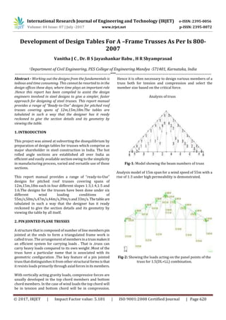
- 1. International Research Journal of Engineering and Technology (IRJET) e-ISSN: 2395-0056 Volume: 04 Issue: 07 | July -2017 www.irjet.net p-ISSN: 2395-0072 © 2017, IRJET | Impact Factor value: 5.181 | ISO 9001:2008 Certified Journal | Page 620 Development of Design Tables For A –Frame Trusses As Per Is 800- 2007 Vanitha J C , Dr. B S Jayashankar Babu , H R Shyamprasad 1Department of Civil Engineering, PES College of Engineering Mandya -571401, Karnataka, India ---------------------------------------------------------------------***--------------------------------------------------------------------- Abstract - Working out the designs from the fundamentals is tedious and time consuming. This cannot be resorted to in the design offices these days, where time plays an important role .Hence this report has been compiled to assist the design engineers involved in steel designs to give a simpler, faster approach for designing of steel trusses. This report manual provides a range of “Ready-to-Use” designs for pitched roof trusses covering spans of 12m,15m,18m.The tables are tabulated in such a way that the designer has it ready reckoned to give the section details and its geometry by viewing the table. 1. INTRODUCTION This project was aimed at subverting the disequilibrium by preparation of design tables for trusses which comprise as major shareholder in steel construction in India. The hot rolled angle sections are established all over India as efficient and easily available section owing to the simplicity in manufacturing process, varied and versatile use of these sections. This report manual provides a range of “ready-to-Use” designs for pitched roof trusses covering spans of 12m,15m,18m each in four different slopes 1:3,1:4,1:5 and 1:6.The designs for the trusses have been done under six different wind loading conditions of 55m/s,50m/s,47m/s,44m/s,39m/sand33m/s.Thetableare tabulated in such a way that the designer has it ready reckoned to give the section details and its geometry by viewing the table by all itself. 2. PIN JOINTED PLANE TRUSSES A structure that is composed of number of line members pin jointed at the ends to form a triangulated frame work is called truss .The arrangementofmembersina trussmakesit an efficient system for carrying loads . That is ,truss can carry heavy loads compared to its own weight .Most of the truss have a particular name that is associated with its geometric configuration .The key feature of a pin jointed truss that distinguishes it from other structural formsisthat it resists loads primarily through axial forcesinitsmembers. With vertically acting gravity loads, compressive forces are usually developed in the top chord members and bottom chord members. In the case of wind loads the top chord will be in tension and bottom chord will be in compression. Hence it is often necessary to design various members of a truss both for tension and compression and select the member size based on the critical force. Analysis of truss Fig-1: Model showing the beam numbers of truss Analysis model of 15m span for a wind speed of 55m with a rise of 1:3 under high permeability is demonstrated. Fig-2: Showing the loads acting on the panel points of the truss for 1.5(DL+LL) combination.
- 2. International Research Journal of Engineering and Technology (IRJET) e-ISSN: 2395-0056 Volume: 04 Issue: 07 | July -2017 www.irjet.net p-ISSN: 2395-0072 © 2017, IRJET | Impact Factor value: 5.181 | ISO 9001:2008 Certified Journal | Page 621 Fig- 3: showing the Deflection profile of the truss for the top chord member Comparison between LSM AND WSM in terms of Weight. Graph -1: Showing the weight in Kg for 12 m span under different wind speeds in LSM and WSM for medium permeability Graph -2: Showing the weight in Kg for 12m, 15 m and 18m spans under different wind speeds in LSM and WSM for High permeability 3. CONCLUSIONS The above data analysis and interpretation from all the graphs envisages that, Limit state method for higher spans of the trusses (say > 15m) with different wind speeds, it is possible to save 10- 12% of steel in comparison with the working stress method. Limit state method also, for the lower spans (say<12m), it is possible to save 5-6% of steel on an average as compared with the working stress method. Significant amount of material can be saved under different wind speeds in higher spans thereby achieving a good economy.Thus,thisbook can be used as a ready reckoned for practice engineers in the field of steel construction and design. 4. REFERENCES [1] Dr. S.K. Dubey, Prakash Sangamnerkar And PrabhatSoni, “Analysis of Steel Roof Truss Under Normal Permeability Condition”, International Journal of Advanced Engineering Research and Studies, Vol. I, Issue IV, pp.8-12, 2012. [2].Dr. N. Subramanian, “Code Of Practiceon Steel Structures -A Review Of IS 800: 2007”, Computer Design Consultants, Gaithersburg, MD 20878, USA [3]. Azhar i Bagadia, “Comparison of response of industrial structure as per IS: 1893- 1984 with IS: 1893 (part-4)”, International Journal of AdvancedEngineeringResearch and Studies, Vol.1, Issue III, pp.95-97, 2012.