This document discusses the design of tower foundations. It notes that tower foundations make up 20-40% of total tower costs. The document presents a computer program written in BASIC to optimally design tower foundations. The program uses concepts like calculating the uplift resistance provided by soil weight in an inverted cone or pyramid shape. It considers factors like soil type, depth, and dimensions to calculate safety factors against uplift and sliding. The overall goal of the program is to aid in producing economical and reliable tower foundation designs.
Fluid and structural modeling of cavitating propeller flowsPhuong Dx
This document summarizes previous research on modeling cavitating propeller flows and hydroelastic effects. It presents the objective to develop a coupled boundary element-finite element model to predict cavitation patterns and hydroelastic response of propellers. An overview is given of the boundary element formulation used, including the assumptions of potential, incompressible, and cavitating sheet flow. Boundary conditions at wetted surfaces and cavities are described. Validation with experiments is discussed.
Closed-Form Expressions for Moments of Two-Way Slabs under Concentrated LoadsIOSR Journals
The document presents closed-form expressions for determining the bending moments in two directions of a rectangular two-way slab under a concentrated load uniformly distributed over a defined area. Two expressions are derived based on elastic analysis and Navier's method. The expressions relate the bending moments to factors that influence them, including the span ratio, the dimensions ratio of the loaded area, and the ratio of the short span to the parallel length of the loaded area. Comparisons are made between results from the new expressions, an approximate method in the Egyptian code ECCS 203-2007, Pigweed's theory, and finite element analysis. Significant differences are found between the code's method and finite element results, while Pigweed's theory agrees well with finite element
Behavioural studies of floating column on framed structureeSAT Journals
Abstract RCC concrete column means cement concrete reinforced with steel bars, steel plates, steel mesh etc. to increase the tension withstanding capacity of the structure. The term floating column means that the column is floated between two floors. Various types of structures G+3, G+5 and G+10 for RCC column and floating column are analyzed. The difference between G+3, G+5 and G+ 10 structures are shown by graphs and charts. Comparison will be done on bending moment and shear force between these structures. This paper presents the analysis of floating column and RCC column by using STAAD PRO V8i. Keywords: Floating Column, RCC column shear force and bending moment.
Comparison of performance of lateral load resisting systems in multi storey f...eSAT Journals
Abstract This paper introduces the comparison between lateral load resisting systems in multi storey building. Multi storey building
composed of very special class of structure and therefore require special treatment. Hence to overcome the effects of seismic
forces, Flat slab system in which slab rests on drop or capital which is connected to column is induced with different load
resisting systems. The combined systems which is used to withstand seismic forces in this study are 1. Flat slab without lateral
load resisting system, 2. Flat slab with shear wall, 3. Flat slab with infill wall, 4. Flat slab with bracings, 5. Flat slab with shear
wall and bracings. ETABS software version is used to accomplish dynamic analysis and also building is investigated for nonlinear
static analysis in order to identify seismic demands. From the obtained results conclusions are drawn.
Keywords: Capital, Bracings, Dynamic, and Treatment etc…
IRJET- Composite Column Subjected to Non-Linear Time History Method in Compar...IRJET Journal
The document compares the seismic performance of a 15-story building with a composite steel-concrete frame to a conventional reinforced concrete (RC) frame using time history analysis. The building models have column spacings of either 5m or 10m and are subjected to seismic zone IV ground motions. Parameters such as displacements, drifts, accelerations, forces, stiffness, and base shear are compared between the composite and RC frame models. The results found that the composite structure performed better in terms of lower displacements and drifts. The composite structure was also found to be more economical.
A Comparative Analysis of R.C.C Elevated Water Tank on Sloping & Leveled GroundIRJET Journal
This document presents a comparative analysis of reinforced concrete elevated water tanks built on sloping and level ground. A Staad.pro model was created of a 1 lakh liter capacity tank with 3 levels and 6 columns. Loads including self-weight, live load, wind, and earthquake were applied according to Indian codes. Parameters like base shear, peak storey shear, column shear forces, and nodal displacements were compared between the sloping and level ground models under different water levels and zone factors. The results show that base shear, peak storey shear, and column shear forces tend to be higher for the level ground model and increase with higher zone factors, while displacements are generally lower for the sloping ground model.
Seismic response of multi storey irregular building with floating columneSAT Journals
Abstract
In recent times, multi-storey buildings in urban cities are required to have column free space due to shortage of space, population and also for aesthetic and functional requirements. For this buildings are provided with floating columns at one or more storey. These floating columns are highly disadvantageous in a building built in seismically active areas. The earthquake forces that are developed at different floor levels in a building need to be carried down along the height to the ground by the shortest path. Deviation or discontinuity in this load transfer path results in poor performance of the building. In this paper, the critical position of floating column in vertically irregular buildings has been discussed for G+5 and G+7 RC buildings for zone II and zone V. Also the effect of size of beams and columns carrying the load of floating column has been assessed. The response of building such as storey drift, storey displacement and storey shear has been used to evaluate the results obtained using ETABS software.
Keywords: Floating column, Irregular building, Response spectrum method
Soil Structure Interaction Effect on the Dynamic Analysis of Wind Turbine TowerIRJET Journal
This document discusses the effects of soil-structure interaction on the dynamic analysis of wind turbine towers. It presents a study where a wind turbine tower model is analyzed both with and without considering the soil conditions. The soil is modeled using Winkler springs in SAP2000 software. Key results analyzed include natural frequency, top displacements, base shear, and time period. The study found that considering soil-structure interaction increased the natural time period and top displacements, while decreasing the base shear. The effects were more pronounced for softer soil conditions. Accounting for soil flexibility was determined to be important for accurately analyzing the seismic response of wind turbine towers.
An analysis of multi-storey building with floating and non-floating column un...IRJET Journal
1) The document analyzes the effects of floating columns in multi-storey buildings under seismic loading in different zones.
2) Static and equivalent static analyses were performed on models with and without floating columns to study structural response quantities like base shear, storey drift and displacements.
3) The results show that buildings with floating columns in seismic zones have increased displacements and decreased base shear and stiffness compared to buildings without floating columns. Floating columns are therefore not advisable in high seismic zones.
Design And Analysis Of Precast Load Bearing Walls For Multi Storey Building ...IJMER
In the present scenario of construction industry, time of construction is very crucial factor.
Pre-cast construction is gaining significance in general and urban areas in particular. The precast
technology is a viable and alternative technique to reduce the construction time. G+11 storey live
project is taken for analysis and design with load bearing walls. Design of precast wall panels and
design of precast slabs is carried using Indian codes subjected to gravity and lateral loads (seismic and
wind). Connections of wall to wall, wall to slab and foundation beam to wall is designed. The structural
system consists of load bearing walls and one-way slabs for gravity and lateral loads have been taken
for analysis using ETABS. Various wall forces, displacements and moments have been worked out for
different load combinations. Data base is presented for the worst load combination
EXPERIMENTAL STUDY ON COIR FIBRE REINFORCED FLY ASH BASED GEOPOLYMER CONCRETE...IAEME Publication
Background/Objectives: By using the fly residue as option substance to bond in concrete it reduces the usage of normal Portland cement in usual concrete which results in the development of Geopolymer concrete furthermore in the lessening of CO2 levels which thusly reduces the Global Warming. Methods/Statistical analysis: This paper presents the trial examination done on the execution of coir fibre reinforced fly residue based geopolymer concrete subjected to severe ecological conditions. The mixes were considered for molarity of 10M. The basic arrangement utilized for present revise is the blend of sodium silicate and sodium hydroxide arrangement with the proportion of 1:2.5. Coir fibre with the varying percentages of 0, 0.75, 1.5, 2.25 and 3 are used as fibre reinforcement. The test specimens of 150mmx150mmx150mm cubes, 150mmx300mm cylinders, 1000mmx150mmx150mm beams are cast and cured under encompassing temperature conditions. Findings: The geopolymer solid examples are tried for their compressive quality, flexural and split tractable tests at 7days, 14days and 28days.The test grades demonstrate that the blend of fly ash and coir fibre can be used for the improvement of geopolymer concrete. Applications: It possesses superior distinctiveness such as high strength, very little drying shrinkage , low creep, durable nature, eco-friendly, fire proof ,better compressive strength etc to be used as an alternative of OPC
Behavior of plan irregularites using composite members by varying column spac...eSAT Journals
Abstract
Several studies proofs that the weaker columns has low seismic resistance, for this it is need to make the column stronger. The stronger columns can be obtained by many ways, here in this paper steel-concrete composite columns are considered. Use of composite columns in construction reduces the cross-section of the columns throughout the building and also increases the lateral-load resisting capacity to columns. The models consists of G+10, G+15, G+20 stories of Rectangular, L, T and plus shaped structures in which column spacing are varied as 3m, 4m, 5m and 6m along both directions in all structures. For all models the composite-column of size 450x450mm (ISMB 250) is kept constant, only the beam size has been varied accordingly while modeling a structure. The Response Spectrum analysis is done for all the buildings using ETABS version 15. Study is based on the performance of a multi-story building with plan irregularity under major earthquake forces by considering parameters like displacement, storey shear and drifts. Even though the cross section of the column considered is very small for tall buildings, the structure behaves stiff for severe seismic zone-V and also for different conditions; this is done by introducing steel-concrete composite column in a given building. Hence it is concluded that the use of composite columns in construction resists the lateral forces for many vulnerable conditions.
Keywords: Composite Column, Irregular Structure, Seismic Zone, Varying Height, Column Spacing.
Optimization of Pre Engineered BuildingsIJERA Editor
Pre-engineered buildings have become quite popular in the last few years. The main advantages are speed of construction and good control over quality. However there is not much information on its economy. There are several parameters like the inclination of the gable, spans, bay spacing, which control the cost of the structure. In the present paper the above parameters are varied systematically and in each case the gable frame designed for the common loads DL, LL, EQ, and WL. The quantity in each case is obtained and finally the structure which regulates the lowest quantity of steel is recommended.
Numerical simulation of laterally loaded pileDr. Naveen BP
This document presents a finite element model simulation of a lateral load test on a 1m diameter bored pile embedded in residual soils. The pile and soil were modeled in PLAXIS 2D, with the soil represented by a Mohr-Coulomb model and the pile as a beam element. The model results showed good agreement with load-displacement curves from the field test. However, the field test was unable to apply loads high enough to reach design code displacement limits due to limitations of test equipment for large piles in residual soils. The numerical model can simulate larger displacements to evaluate pile behavior under higher loads.
The document summarizes an experimental study on the aerodynamic characteristics of non-circular high-rise buildings. Four building models were tested in a wind tunnel: a triangular prism, tapered square, square with sharp corners, and square with filleted corners. Drag force, pitching moment, and surface pressure were measured at angles of 0°, 90°, 180°, and 270° to the flow at velocities of 15m/s, 20m/s, and 25m/s. The tapered square model generally experienced lower drag and pitching moments than the other models. Surface pressure was highest on the square with filleted corners and lowest on the tapered square model.
Comparative Parametric Study of Seismic Behaviour of RC Framed Building With ...IRJET Journal
This document presents a comparative parametric study of the seismic behavior of reinforced concrete framed buildings with and without floating columns in different configurations. Three models of a G+20 building were analyzed using software: a normal model without floating columns, a model with 12 alternate floating columns including corners, and a model with 12 alternate floating columns excluding corners. Results showed column forces, beam forces, base shear, displacement, and drift increased in the models with floating columns compared to the normal model without floating columns. The model with floating corner columns experienced more severe increases in design parameters than the model without floating corner columns. Therefore, floating columns should be avoided in high seismic zones and corner columns should not be floated if they must be used.
Mathematical analysis of section properties of a platform integrated with veh...Dr.Vikas Deulgaonkar
The present work depicts mathematical behavior of a vehicle mounted platform/frame integrated with chassis structure in terms of plane stresses and plane strains for non-uniform loads. The load type considered in present work is concentrated load for which the mathematical model is formulated. A different type of combination of longitudinal and cross members in platform/frame design is formulated. The dimensions of platform members are determined using IS standards. After analysis of all possible combinations of longitudinal and cross members present design is anticipated. Section properties of longitudinal and cross members of the platform are determined & deduction of bending stress and shear force based on the load pattern are the fundamental steps in design and analysis of platform structure. The peculiarity of this analysis is the calculation of combined section modulus of three members. These are evaluated by excel programs developed indigenously.
Comparison of 3_d_finite_element_stability_analysis_with_3d_limit_equilibriumdgjd
This document compares 3D finite element slope stability analysis using shear strength reduction with 3D limit equilibrium analysis. It presents the results of two example slope stability analyses using both methods. The results show reasonable agreement between the two methods, with calculated factors of safety differing by less than 5% in both examples. This demonstrates the usefulness of both 3D limit equilibrium and finite element shear strength reduction methods for analyzing fundamentally 3D slope geometries and loadings.
A study-of-the-behaviour-of-overlying-strata-in-longwall-mining-and-its-appli...Agustino Rosas
This study investigated the behavior of rock strata above a longwall coal mining face. Instruments were installed in boreholes above an active longwall face in China to monitor the movement of rock layers over time. The data showed three zones of behavior: 1) an abutment pressure zone with little movement near the face, 2) a bed separation zone where rock layers began to separate as the face passed, and 3) a consolidation zone further away where the layers reconsolidated. By analyzing the displacement curves, a structural model was created to examine how forces are distributed between the rock blocks as mining progresses. This model can help explain some phenomena observed during longwall mining such as ground subsidence and roof pressure development.
Analysis of multistoried braced steel space frame subjected to gravity and se...IJERA Editor
This document analyzes multistory steel space frames with bracing subjected to gravity and seismic loads. Three models are analyzed: an unbraced frame, a frame with cross bracing, and a frame with single diagonal bracing. Frames ranging from 5 to 11 stories tall and with 3, 5, or 7 bays are modeled and analyzed. Results show that braced frames experience lower displacements and forces than unbraced frames. Cross bracing produces smaller axial forces in braces than single diagonal bracing. Soft stories at intermediate levels perform better than soft stories at the ground level. Partially braced frames with 1 or 2 bays of bracing provide adequate stiffness at a lower cost. Overall, cross bracing is
This document discusses advances in numerical simulation of extrusion processes using the finite element method. It describes three formulations for modeling extrusion - updated Lagrangian, steady state Eulerian, and arbitrary Lagrangian Eulerian (ALE). Recent efforts have focused on improving the ALE formulation in the commercial software DEFORM-3D. The paper summarizes the ALE methodology, describes an industrial extrusion example simulated using the different methods, and compares the finite element predictions to actual experimental results to validate the approaches.
Design & Analysis of High rise Building With & Without Floating Column Using ...IJSRD
At present buildings with floating column is a typical feature in the modern multistory construction in urban India. There are many projects in which floating columns are adopted, especially above the ground floor, where transfer girders are employed, so that more open space is available in the ground floor. As the load path in the floating columns is not continuous, they are more vulnerable to the seismic activity. Sometimes, to meet the requirements these type of aspects cannot be avoided though these are not found to be of safe. Hence, an attempt is taken to study the behavior of a G+15 multi storey building in which some storey’s are considered for commercial purpose and remaining storey’s are for residential purpose. This paper studies the comparison & seismic analysis of the multistory buildings with floating column and without floating column. Finally, analysis & results in the high rise building such as storey drifts, storey displacement, and Base shear were shown in this study. Design and Analysis was carried out by using Extended Three Dimensional Analysis of Building Systems (ETABS) Software.
IJRET : International Journal of Research in Engineering and Technology is an international peer reviewed, online journal published by eSAT Publishing House for the enhancement of research in various disciplines of Engineering and Technology. The aim and scope of the journal is to provide an academic medium and an important reference for the advancement and dissemination of research results that support high-level learning, teaching and research in the fields of Engineering and Technology. We bring together Scientists, Academician, Field Engineers, Scholars and Students of related fields of Engineering and Technology
This document presents the results of a pushover analysis conducted on 9 structural models with varying plan irregularities. The models were analyzed using ETABS software to determine key parameters such as lateral displacement, story drift, base shear, and performance point. The results show that structures with complex geometries experience greater lateral displacement, story drift, and base shear compared to regular structures. Pushover curves indicate that irregular structures may not achieve desired performance levels at lower displacement thresholds. In conclusion, simple and regular building geometries perform better during earthquakes by attracting fewer seismic forces.
This document discusses considerations for the design of tower foundations. It notes that tower foundations typically make up 20-40% of total tower costs. The design process is iterative and aims to ensure stability against overturning, sliding, uplift and tilting due to soil pressures. It outlines the two-part design process of stability analysis and strength design to proportion foundation components to loads. Uplift resistance is a key factor in footing size selection. Methods to check for sliding, overturning and uprooting of foundations are presented.
STUDIES OF ANALYSIS AND DESIGN FOR MULTI-STORIES STRUCTURES WITH TRANSFER PLA...IRJET Journal
This document summarizes a study analyzing and designing a multi-story building with a transfer plate using ETABS software. Key points:
- Transfer plates are commonly used in high-rise buildings to allow more open space on lower floors for parking while allowing closely spaced columns above for residential floors.
- The study models a building with 6 parking floors and 15 residential floors above a transfer plate located at the 6th level.
- Global analysis in ETABS is used to analyze lateral responses, displacement, story stiffness, and plate bending moments to verify design. Results like story displacements and period ratios are within code limits.
- Plate responses like maximum bending moments are compared to separate plate analysis, finding agreement.
A raft foundation is a large concrete slab that interfaces columns with the base soil. It can support storage tanks, equipment, or tower structures. There are different types including flat plate, plate with thickened columns, and waffle slab. The structural design uses conventional rigid or flexible methods. It involves determining soil pressures, load eccentricities, moment and shear diagrams for strips, punching shear sections, steel reinforcement, and checking stresses. A beam-slab raft foundation design follows the same process as an inverted beam-slab roof.
IRJET - Experimental Investigation on Behaviour of Footings Subjected to Hori...IRJET Journal
- The document reports on an experimental investigation into the behavior of circular footings subjected to horizontal loads.
- A series of laboratory load tests were conducted where parameters like depth of footing, soil type, ratio of vertical to horizontal load were varied.
- The tests found that lateral deformation decreases with increasing depth of footing and vertical load, as these factors increase confinement of the soil around the footing.
- Inclination or tilt of the footing under combined loading was also found to decrease with increased depth.
- The addition of micropiles was found to improve the lateral load-deformation behavior by decreasing lateral displacement.
A Review Paper on Analysis and Design of Precast Box Culvert BridgeIRJET Journal
This document summarizes a research paper on the analysis and design of precast box culvert bridges. It begins with an abstract stating that box culverts are monolithic structures used to bridge roads and waterways. The document then reviews different types of IRC live load considerations for design, including Class 70R, Class A, and Class B loads. It discusses design considerations for box culverts like earth pressure effects, cushion depth, and structural elements to withstand bending moments and shear stresses. The methodology section outlines the steps used in modeling and analyzing a box culvert in STAAD Pro software. It also compares results for monolithically cast and separately cast top slabs. The conclusion states that box culverts are a robust, rigid
The ultimate capacities of single piles utilized in ten projects in Basra-Iraq are
evaluated using: various interpretations of pile load test results; several static
methods based on site investigation programs; and the finite element method via
(PLAXIS-3D).For the well-behaved tests, it is realized that the load-settlement data
can be best fitted by a hyperbola. Accordingly, Rollberg method well-harmonizes the
test results and allows various interpretation methods to be applied on the
extrapolated curves. It is found that, the static methods spread over a wide range of
values. Finite element analyses exhibited good agreement to the measured values. It
produces failure loads, almost, similar to that obtained from Rollberg method. The
finite element analyses revealed local settlement of (0.6% - 1.8%) of the pile diameter
to mobilize the ultimate skin resistance.
STRUCTURAL ANALYSIS OF BRIDGES AND PILE FOUNDATION SUBJECTED TO SEISMIC LOADSIRJET Journal
This document summarizes research on analyzing the structural performance of bridge foundations and piles subjected to seismic loads. A numerical model was developed using ANSYS software to evaluate the behavior of bridge structures and pile foundations made of different materials, including carbon fiber reinforced steel, epoxy fiber reinforced steel, and structural steel. The model subjected the structures to varying seismic loading conditions. Results showed that carbon fiber reinforced structural steel performed better than epoxy fiber reinforced steel and structural steel, with less displacement observed under seismic loads. The objectives of the research were to study the performance of different bridge pile foundation materials and bridge structures under seismic loads and vibrations. The methodology involved modeling the bridge and pile foundations in ANSYS and applying seismic loads to analyze structural
The design of Elements of Lifts and Escalator from Civil Engineering point of view. Mainly Raft foundation, Machine Foundation, and Shear walls are discussed.
PREDICTING BEARING STRENGTH CHARACTERISTICS FROM SOIL INDEX PROPERTIESIAEME Publication
The bearing strength of foundation soil is a major design criteria for civil engineering structures. This study aims to estimate the bearing strength, namely California Bearing Ratio (CBR) and ultimate bearing capacity, from simple and easy measured soil index properties. Comprehensive literature concerning bearing strength characteristics and their prediction equations proposed by previous researchers were reviewed. Laboratory investigation was conducted on two different soils compacted at various placement conditions (i.e. moisture content and dry density) and tested using CBR and triaxial tests. Based on test results, linear relationships of unsoaked CBR and ultimate bearing capacity with the consistency factor which is formed by combining placement conditions and soil intrinsic parameters had been developed.
IRJET- Parametric Study of Foundation of Tension and Suspension Tower wit...IRJET Journal
This document presents a parametric study of the foundations for suspension and tension transmission towers with square and rectangular bases. Foundations were designed for five different soil conditions and five base width ratios, changing the ratio of the longitudinal face to transverse face. The minimum cost foundation for each soil condition was determined. For isolated foundations, the minimum cost ratio was between 1:1.2 to 1:1.3. For pile foundations, the minimum cost ratio was between 1:1.3 to 1:1.4. The percentage cost reduction was 8-9% for isolated foundations and 13% for pile foundations when optimizing the base width ratio.
IRJET- Planning, Design & Analysis of a Commercial Building with Flat Sla...IRJET Journal
This document summarizes the planning, design, and analysis of a commercial building with flat slab structure considering earthquake forces using ETABS software. 25 models of multi-story reinforced concrete flat slab structures with varying aspect ratios and slenderness ratios were modeled and analyzed using response spectrum analysis. The objectives were to calculate design lateral forces, study structural response in seismic zone III, and determine limit aspect and slenderness ratios for structural safety and stability.
Numerical simulation and optimization of pile designIRJET Journal
1) The document discusses numerical simulation and optimization of pile design for underground structures. It aims to analyze the performance of pile foundations made of different materials under varying loading conditions.
2) A finite element model is created to simulate the structure and analyze it under different loads. The maximum displacement and stresses increase with increasing load.
3) Taguchi method and ANOVA techniques are used to optimize the design by determining the relationship between dependent and independent variables. The study finds that blast load has a more significant impact on the structure's performance than pressure.
IRJET- Finite Element Analysis of T-Shaped Footing of Varying Projection Loca...IRJET Journal
This document summarizes a finite element analysis of T-shaped footings with varying projection locations and depths, conducted using ANSYS software. T-shaped footings have a vertical projection at the center to improve bearing capacity under central loading and resist overturning and sliding. Various T-shaped footing models were analyzed with different projection depths (D/B ratios) and positions (C/B ratios), under eccentric vertical loading. The results showed that increasing the projection depth and positioning it closer to the load eccentricity reduced footing tilt, displacements, and stresses. At an eccentricity ratio of 0.15, a tilt within permissible limits occurred for D/B ratios of 0.75 and 1.0.
IRJET- Parametric Study on Behaviour of RCC Box Culvert for Dynamic LoadingIRJET Journal
This document describes a parametric study on the behavior of reinforced concrete box culverts under dynamic loading. It discusses the modeling and analysis of a box culvert bridge using STAAD.Pro software. The design loads considered are per IRC 6. The document provides details of the hydraulic calculations and design of the box culvert, including the discharge calculation, dimensions of the culvert, and loading cases analyzed. It analyzes three cases: when the top slab carries dead and live loads and the culvert is empty, when it carries both loads and is full, and when the slab does not carry live loads and it is full.
This document provides an overview of pile foundations and their design. It discusses different types of piles including end bearing piles, friction piles, displacement piles, and replacement piles. Modes of pile failure and factors in total and effective stress analysis are examined. Advantages and disadvantages of displacement and replacement piles are compared. Methods for predicting the ultimate capacity of axially loaded single piles in soil are outlined, including considerations for driven piles in clays and bored piles in both granular and clay soils. Load-settlement behavior of friction and end bearing piles is also addressed.
Assessment of Soil Structure Interaction on RCC Underpass BridgeIRJET Journal
This document analyzes the soil-structure interaction of reinforced concrete underpass bridges. It presents a case study of single cell and double cell underpass bridge models analyzed using finite element software. Three foundation conditions are considered: rigid supports, springs at the base only, and springs at the base and sidewalls. Results for bending moment, shear force, and axial thrust are presented for different load combinations and subgrade modulus values. The study found that accounting for soil-structure interaction reduces stresses in the structure compared to assuming rigid supports. Stresses were lowest for the load combination of dead load, earth pressure, and water pressure.
This document summarizes the development and operation of a real-time monitoring system for validating driven cast in-situ (DCIS) pile installation. Key parameters such as length, hammer blows, and resistance are recorded during installation. The data is processed to calculate dynamic drive resistance (Ru) and predict pile performance. The system allows engineers to view installation data in real-time. A case study demonstrates how installation data validated the performance of large diameter DCIS piles used to support a new bridge.
The present work is focused on understanding the uplift capacity of vertical and inclined piles passing through two layered soil and subjected to the inclined loads. The study was carried out using finite element software MIDAS 3D. The foundation soil was modeled as an elasto-plastic material
obeying the Mohr-Coulomb failure criterion. The parametric studies were performed by varying the diameter of pile, angle of inclination of load (α) and pile angle (θ). It was observed that the uplift capacity of pile depends upon these parameters. The uplift capacity of pile varies with inclination of pile angle and inclination of load.
The document provides an analysis of the slope design for an open pit operation submitted by Andrews Surface-Design LTD. West Country Minerals conducted an independent review using software like DIPS, RocLab, RocPlane, and Slide. The analysis examined potential failure mechanisms like planar, wedge, and toppling failures. It also analyzed the stability of individual benches and the overall slope. The review found that some benches would fail without support but adding tension bolts could achieve the target safety factors, particularly if higher bolt tension is used for seismic conditions. Overall, the analysis found the slope design to be stable but recommended some amendments to bolt support and further sensitivity analysis.
Structural Design and Rehabilitation of Reinforced Concrete StructureIJERA Editor
Effective rehabilitation scheme for failed structure demands methodical analysis of various
causes of failure and intended service loads and other functional details, The actual study under deliberation is
the best example of rehabilitation Structural element – Basement RCC raft, failed to sustain uplift due to ground
water table. This paper dealt with the rehabilitation of basement RCC raft foundation considering various design
aspects like uplift due to ground water table, sub-soil properties and restriction on depth of raft to suffice
available headroom for intended use.
Advanced control scheme of doubly fed induction generator for wind turbine us...IJECEIAES
This paper describes a speed control device for generating electrical energy on an electricity network based on the doubly fed induction generator (DFIG) used for wind power conversion systems. At first, a double-fed induction generator model was constructed. A control law is formulated to govern the flow of energy between the stator of a DFIG and the energy network using three types of controllers: proportional integral (PI), sliding mode controller (SMC) and second order sliding mode controller (SOSMC). Their different results in terms of power reference tracking, reaction to unexpected speed fluctuations, sensitivity to perturbations, and resilience against machine parameter alterations are compared. MATLAB/Simulink was used to conduct the simulations for the preceding study. Multiple simulations have shown very satisfying results, and the investigations demonstrate the efficacy and power-enhancing capabilities of the suggested control system.
Using recycled concrete aggregates (RCA) for pavements is crucial to achieving sustainability. Implementing RCA for new pavement can minimize carbon footprint, conserve natural resources, reduce harmful emissions, and lower life cycle costs. Compared to natural aggregate (NA), RCA pavement has fewer comprehensive studies and sustainability assessments.
A review on techniques and modelling methodologies used for checking electrom...nooriasukmaningtyas
The proper function of the integrated circuit (IC) in an inhibiting electromagnetic environment has always been a serious concern throughout the decades of revolution in the world of electronics, from disjunct devices to today’s integrated circuit technology, where billions of transistors are combined on a single chip. The automotive industry and smart vehicles in particular, are confronting design issues such as being prone to electromagnetic interference (EMI). Electronic control devices calculate incorrect outputs because of EMI and sensors give misleading values which can prove fatal in case of automotives. In this paper, the authors have non exhaustively tried to review research work concerned with the investigation of EMI in ICs and prediction of this EMI using various modelling methodologies and measurement setups.
Literature Review Basics and Understanding Reference Management.pptxDr Ramhari Poudyal
Three-day training on academic research focuses on analytical tools at United Technical College, supported by the University Grant Commission, Nepal. 24-26 May 2024
ACEP Magazine edition 4th launched on 05.06.2024Rahul
This document provides information about the third edition of the magazine "Sthapatya" published by the Association of Civil Engineers (Practicing) Aurangabad. It includes messages from current and past presidents of ACEP, memories and photos from past ACEP events, information on life time achievement awards given by ACEP, and a technical article on concrete maintenance, repairs and strengthening. The document highlights activities of ACEP and provides a technical educational article for members.
CHINA’S GEO-ECONOMIC OUTREACH IN CENTRAL ASIAN COUNTRIES AND FUTURE PROSPECTjpsjournal1
The rivalry between prominent international actors for dominance over Central Asia's hydrocarbon
reserves and the ancient silk trade route, along with China's diplomatic endeavours in the area, has been
referred to as the "New Great Game." This research centres on the power struggle, considering
geopolitical, geostrategic, and geoeconomic variables. Topics including trade, political hegemony, oil
politics, and conventional and nontraditional security are all explored and explained by the researcher.
Using Mackinder's Heartland, Spykman Rimland, and Hegemonic Stability theories, examines China's role
in Central Asia. This study adheres to the empirical epistemological method and has taken care of
objectivity. This study analyze primary and secondary research documents critically to elaborate role of
china’s geo economic outreach in central Asian countries and its future prospect. China is thriving in trade,
pipeline politics, and winning states, according to this study, thanks to important instruments like the
Shanghai Cooperation Organisation and the Belt and Road Economic Initiative. According to this study,
China is seeing significant success in commerce, pipeline politics, and gaining influence on other
governments. This success may be attributed to the effective utilisation of key tools such as the Shanghai
Cooperation Organisation and the Belt and Road Economic Initiative.
Electric vehicle and photovoltaic advanced roles in enhancing the financial p...IJECEIAES
Climate change's impact on the planet forced the United Nations and governments to promote green energies and electric transportation. The deployments of photovoltaic (PV) and electric vehicle (EV) systems gained stronger momentum due to their numerous advantages over fossil fuel types. The advantages go beyond sustainability to reach financial support and stability. The work in this paper introduces the hybrid system between PV and EV to support industrial and commercial plants. This paper covers the theoretical framework of the proposed hybrid system including the required equation to complete the cost analysis when PV and EV are present. In addition, the proposed design diagram which sets the priorities and requirements of the system is presented. The proposed approach allows setup to advance their power stability, especially during power outages. The presented information supports researchers and plant owners to complete the necessary analysis while promoting the deployment of clean energy. The result of a case study that represents a dairy milk farmer supports the theoretical works and highlights its advanced benefits to existing plants. The short return on investment of the proposed approach supports the paper's novelty approach for the sustainable electrical system. In addition, the proposed system allows for an isolated power setup without the need for a transmission line which enhances the safety of the electrical network
DEEP LEARNING FOR SMART GRID INTRUSION DETECTION: A HYBRID CNN-LSTM-BASED MODELgerogepatton
As digital technology becomes more deeply embedded in power systems, protecting the communication
networks of Smart Grids (SG) has emerged as a critical concern. Distributed Network Protocol 3 (DNP3)
represents a multi-tiered application layer protocol extensively utilized in Supervisory Control and Data
Acquisition (SCADA)-based smart grids to facilitate real-time data gathering and control functionalities.
Robust Intrusion Detection Systems (IDS) are necessary for early threat detection and mitigation because
of the interconnection of these networks, which makes them vulnerable to a variety of cyberattacks. To
solve this issue, this paper develops a hybrid Deep Learning (DL) model specifically designed for intrusion
detection in smart grids. The proposed approach is a combination of the Convolutional Neural Network
(CNN) and the Long-Short-Term Memory algorithms (LSTM). We employed a recent intrusion detection
dataset (DNP3), which focuses on unauthorized commands and Denial of Service (DoS) cyberattacks, to
train and test our model. The results of our experiments show that our CNN-LSTM method is much better
at finding smart grid intrusions than other deep learning algorithms used for classification. In addition,
our proposed approach improves accuracy, precision, recall, and F1 score, achieving a high detection
accuracy rate of 99.50%.
Embedded machine learning-based road conditions and driving behavior monitoringIJECEIAES
Car accident rates have increased in recent years, resulting in losses in human lives, properties, and other financial costs. An embedded machine learning-based system is developed to address this critical issue. The system can monitor road conditions, detect driving patterns, and identify aggressive driving behaviors. The system is based on neural networks trained on a comprehensive dataset of driving events, driving styles, and road conditions. The system effectively detects potential risks and helps mitigate the frequency and impact of accidents. The primary goal is to ensure the safety of drivers and vehicles. Collecting data involved gathering information on three key road events: normal street and normal drive, speed bumps, circular yellow speed bumps, and three aggressive driving actions: sudden start, sudden stop, and sudden entry. The gathered data is processed and analyzed using a machine learning system designed for limited power and memory devices. The developed system resulted in 91.9% accuracy, 93.6% precision, and 92% recall. The achieved inference time on an Arduino Nano 33 BLE Sense with a 32-bit CPU running at 64 MHz is 34 ms and requires 2.6 kB peak RAM and 139.9 kB program flash memory, making it suitable for resource-constrained embedded systems.
Low power architecture of logic gates using adiabatic techniquesnooriasukmaningtyas
The growing significance of portable systems to limit power consumption in ultra-large-scale-integration chips of very high density, has recently led to rapid and inventive progresses in low-power design. The most effective technique is adiabatic logic circuit design in energy-efficient hardware. This paper presents two adiabatic approaches for the design of low power circuits, modified positive feedback adiabatic logic (modified PFAL) and the other is direct current diode based positive feedback adiabatic logic (DC-DB PFAL). Logic gates are the preliminary components in any digital circuit design. By improving the performance of basic gates, one can improvise the whole system performance. In this paper proposed circuit design of the low power architecture of OR/NOR, AND/NAND, and XOR/XNOR gates are presented using the said approaches and their results are analyzed for powerdissipation, delay, power-delay-product and rise time and compared with the other adiabatic techniques along with the conventional complementary metal oxide semiconductor (CMOS) designs reported in the literature. It has been found that the designs with DC-DB PFAL technique outperform with the percentage improvement of 65% for NOR gate and 7% for NAND gate and 34% for XNOR gate over the modified PFAL techniques at 10 MHz respectively.
Low power architecture of logic gates using adiabatic techniques
Cimentaciones de torres
1. There has been an increasing trend of construc-
tion of microwave communication and transmis-
sion line towers all over the country. The founda-
tions of such towers constitute nearly 20 to 40
percent of the total cost of towers. However, very
little information is available on the design pro-
cedure of tower foundation. The paper presents
the underlying concepts for designing tower foun-
dations efficiently and economically. A computer
program in BASIC, which uses these concepts,
is also presented. This program may be used to
optimally proportion the tower foundations.
N. $Orarnarf and V. Vaser01
Transmission line towers, antenna towers, towers used for
oil well derricks and mine-shaft equipment, beacon supports.
and observation platform, etc., are examples of self-supporting
towers. Out of these various types of towers, transmission
line towers are subjected to torsional forces, in addition to
other forces.
Normally, the tower foundation constitutes about 20 to 40
percent of the total cost of tower. A rough idea about this
cost could be obtained from the relative weights of the founda-
tion and tower. It was observed that for a 100-m high micro-
wave tower, the weight of the foundation concrete was
around 410t, while the weight of the structural steel of the
tower was only 65t. From the engineering point of view, the
foundation design of towers poses a serious problem due to
different types of soils encountered and also due to the
various forces acting on the foundation. Thus, the structural
engineer is faced with a difficult task of producing econo-
mical and reliable design'. A very little information is avai-
lable for the design of such foundations 1-3' 5-8
The design of tower foundation is basically an interative
procedure. Since the uplift force is predominant, the design
poses a number of problems, and hence, is amenable to
computerization. However, till now, no program is available
in India for the design of these foundations. In this paper a
computer program is presented, based on the provisions of
the recent Indian Codes of Practice 2 '3 '4 . A brief outline of the
procedure to be used for the design of tower foundations is
also described. Salient features of the package developed,
baked on this procedure are enumerated. The package has
been developed using the BASIC language for use on an
IBM PC or compatible machine based on the working stress
method of design. Both unreinforced and reinforced concrete
Dr. N. Subramanian, Chief Executive, Computer Design Consultants, 191
North Usman Road, T. Nagar, Madras 600 017.
Ms V. Vasanthi, Assistant Manager, Computer Design Consultants,
Madras 600 017.
Design of
tower
foundations
sections could be designed by using this program. Different
types of soil conditions, viz., normal dry, wet, submerged,
partially submerged. black cotton, wet black cotton, soft rock,
and hard rock, are considered. Based on this procedure, the
authors have designed a 100-m microwave tower foundation
which was executed by the Indian Telephone Industries in
Rajasthan.
Design
There are two parts in the design. They are: stability analysis,
and strength design. Stability analysis aims at removing the
possibility of failure by overturning, uprooting, sliding and
tilting of the foundation due to soil pressure being in excess
of the ultimate capacity of the soil. The strength design con-
sists of proportioning the components of the foundation to
the respective maximum moment, shear, pull and thrust or
combination of the same.
The type of loading that controls the foundation design
depends mainly on the kind of towers being designed. The
controlling design loads for four-legged lattice towers are
vertical uplift, compression and side thrust.
Depending on the site condition and the forces acting on
the tower legs, one of the following types of foundation is
normally employed:
(i) drilled and/or belled shaft
(ii) pad and chimney
(iii) footing with undercut
(iv) auger with reaming
(v) grillage
(vi) special type.
Selection of foundation type needs judgement and expe-
rience and a careful study of all the parameters. However, in
India, pad and chimney type of foundation is employed for a
majority of towers, and hence, in this paper, the same type of
foundation is considered, Fig 1. The concrete used for the
THE INDIAN CONCRETE JOURNAL ♦ MARCH 1990 135
2. Base plate
t
_7
•
94 ,94w
T.
Anchor bolts
T
ti
Stub angle
B1
TtiC
• Chimney
• reinforcement
WNW -
•
x
1 4_
Chimney-pad type foundation Reinforced concrete foundation
(a) lb)
( C ) (d)
Stub angle
813
Benching of hard rock
– Mors
— Earthcone
Balla
—••-- Coulomb shear friction
Matsuo
Meyerhof and Adams
5000 300
C, psf
30° 20°
0, degree
100
./.
*N.
10
Tw
L
c,
H1 = 50mm
H4 225mm
H5 = 750 mm for partially
submerged soil
H5 1.50m for wet soil
H5 = 750mm for wet soft rock
H5 .0 for dry soil
Fig 1 Different types of tower foundation
foundation is assumed to be of grade M-15 corresponding to
1:2:4 nominal mix with 20mm coarse aggregate for chimney
portion and 40mm coarse aggregate for pyramid or slab
portion. When reinforced concrete foundation is adopted, the
entire footing is assumed to be made of 20mm coarse
aggregate .
Design for uplift resistance
Apart from resisting the vertical compression, the soil surroun-
ding a tower foundation has also to resist a considerable
amount of upward pull and side thrust. As a matter of fact,
the available uplift resistance of the soil is the deciding factor
in selecting the size of the footing. However, unfortunately,
adequate theory has not yet been established for the
accurate assessment of the uplift resistance of the soil mass.
It is generally considered that the resistance to uplift is pro-
vided by the shed, strength of the soil and the weight of the
foundation. Various empirical relationships linking ultimate
holding power to the physical properties of the soil, as well
as the dimensions of the footing have been proposed on the
basis of experimental results 5 .
Calculations of the ultimate uplift capacity obtained by
these methods show a wide fluctuation as shown in Fig 2'.
The method proposed by Meyerhof and Adams, Matsuo and
Fig 2 Comparison of uplift methods
Fig 3 Assumptions and variables used in the computer
program
Balla have been found to be in close agreement for sands
(C = 0), but differ significantly for cohesive soils 4 .
Hence, in the Indian Code2.3 , the traditional method of
assessment of uplift resistance by computing the weight of
earth in the inverted frustum of cone/pyramid, whose sides
136 THE INDIAN CONCRETE JOURNAL ♦ MARCH 1990
3. P
P p
3
P
-2
4
C
B
(IC • M Pp,
Factor of safety against sliding _ 22
5
varies between 0.35 to 0.55
In the program it is taken as 0-35
make an angle with the vertical equal to the angle of internal
friction of the soil, has been considered. In practice, many
designs done on the basis of weight frustum of cone/pyramid
with sides making an angle 20° in the case of non-cohesive
soils and 30° in the case of cohesive soils have been found
to be satisfactory. Though this method is found to give
results within ± 15 percent range of the experimental values,
the results are generally found to be on the conservative
side6•78 . This is because the earth cone method neglects
adhesion or friction along the failure surface.
Referring to Fig 3, the ultimate resistance to uplift will be
given by
U. W. W, (1)
where, Ws weight of soil in frustum of pyramid and 14/, =
buoyant weight of the foundation.
For square footing, which is common for the type of found-
ation shown in Fig 1(a) and (b), the volume of earth in the
frustum of pyramid for dry normal soil as per IS code is
V • D.(133 + 2tanb BD. + 4/3 tan'+ ) (2)
where, Do = depth of pyramid =
B = breadth of footing
0 = angle of repose of soil.
It should be noted that, apart from being a function of the
properties of soil (0, C, etc.), the effective uplift resistance is
also affected by the degree of compaction of the soil, and the
ground water-table at the location of the foundation.
In this program, the earth cone method (i.e. the IS code
method) as well as the method suggested by Meyerhof and
Adams are considered.
For both these methods, equations were derived for find-
ing the volume of earth resisting the uplift considering the fol-
lowing:
normal dry soil and soft rock
wet soil
submerged or partially-submerged soil
if reinforced concrete foundation is chosen, H2 is
assumed as zero (refer Fig 3)
in case where the frustum of earth pyramid of two
adjoining legs superimpose each other, the earth
frustum is assumed to be truncated by a vertical
plane passing through the centre line of the tower
base.
Since the program requires the values of B, H2, and H3,
(which will be known only after designing the foundation), it
gives some approximate values as guidance, which may be
input as the initial values. The program prints the values of
factor of safety against uplift resistance. The user has to
check whether the values of B,, H2, and H3 can be changed
in order that he can reduce the factor of safety to nearly 1.00
so that the optimum design is achieved.
It has to be noted that two values of factor of safety against
uplift are printed, one without considering passive pressure
(IS code method) and the other considering the same. The
user can choose any one of them for optimization, depend-
ing upon his needs.
Check for sliding
The shear force acting on the foundation causes bending
stresses in the unsupported length of the stub angle as well
as in chimney/shaft of the foundation and tends to overturn
the foundation. When the lateral resistance of the adjoining
soil is small or totally neglected as uncertain, the bending
and overturning actions will be more.
However, in tower designs, it is a common practice to
consider the side thrust on the foundation to be resisted by
the passive earth pressure mobilized in the adjoining soils
due to rotation of the footing. Because of the somewhat
larger lateral movement tolerated in the foundation of com-
mon self-supporting, bolted towers, it is permissible to
depend on the mobilization of the passive pressure even
when the foundation construction involves excavation and
provision of backfill; but when such passive pressure is relied
upon, it is mandatory to compact the backfill with special
care.
Stability of a footing under a lateral load will be dependent
upon the amount of passive pressure mobilized in the adjoin-
ing soil as well as the structural strength of the footing in trans-
mitting the load to the soil. Solution of this problem involves
the study of the soil structure interaction and assessment of
the soil pressure for the allowable lateral displacement. A
very little information is available on the soil structure inter-
action of tower foundations.
Hence, in the program for the unreinforced foundation,
the following method is adopted. Referring Fig 4,
+ IP.
Factor of safety against sliding (3) *
Side thrust
where, Pi is the sum of passive pressure components of the
soil, C is the compressive force acting on the foundation, and
is the coefficient of friction, which varies between 0.35 and
0.55 depending on the type of soil. In the program, the con-
servative value of 0.35 has been assumed. However, when
Fig 4 Stability of tower foundation against sliding
THE INDIAN CONCRETE JOURNAL ♦ MARCH 1990 137
4. pp4
pp3
Pp 2
Pn 1
1-•
568 8/6
For stability against overturning
/
Factor of safety -
(W2/2)5 613
4 2 2
(T - Wf ) 8 /3 • S(D e • H4 ) -E Pp; L a i
Where W2 Weight of soil in the cone pyramid for stability
T Uplift on the leg of tower
S. Maximum horizontal shear on tower leg
Wf .• Weight of footing
P p ; Passive pressure
Stub angle
1 I31_4
Section A-A
y 13/2 tan cc
tan a .
(13/2 - y) (1 • tan a )
horizontal projected area of the potential failure cone,
Ap ( 2y • dh ) 2 - dh 2
Neglecting dh,
Ap 4y 2
4 y 2 r c > T
CNI
13/2
tension and side thrust are acting (which is the critical condi-
tion), the above equation is rewritten as
uniform. The unit maximum toe pressure P on the soil can be
determined from the equation:
E P,
Factor of safety (4)
Side thrust
P.
W(1 fie')
— —
AB B
(5)
If the factor of safety is less than the specified value, the
chimney width is increased.
Stability against overturning
Stability of the foundation against overturning may be che-
cked by the following criteria, Fig 5,:
(i) the foundation tilts about a point in its base at a dis-
tance of 1/6th of its width from the toe
(ii) the weight of the footing acts at the centre of the
base
(iii) mainly that part of the cone which stands over the
heel, causes the stabilising moment.
However, for design purposes, this may be taken equal to
half the weight of the cone of earth acting on the base. It is
assumed to act at the tip of the heel, Fig 5.
Design for downward load
The maximum soil pressure below the base of the foundation
(toe pressure) will depend on the vertical thrust on the foot
ing and the moment at the base level due to the horizontal
and other eccentric loadings.
When the vertical load acts eccentrically or the horizontal
shear at the top of the pedestal is transferred to the soil
below the footing, the soil pressure at this level will not be
Fig 5 Stability of tower foundation against overturning
where A and B are the base dimensions of the footing and
e' =- %, in which M = the maximum moment of the loads
taken at the level and mid point of the base, and W = total
vertical thrust including that of the footing. Equation (5) is
applicable when the result lies within the middle third. When
the footing is under biaxial moment, the maximum pressure
at the critical corner should be worked out accordingly.
The maximum pressure on the soil so obtained should not
exceed the safe bearing capacity of the soil. If it exceeds, the
size of the footing is to be increased. The safe bearing
pressure may, however, be increased by 25 percent if the
loading considered includes dead load and wind or earth-
quake loads as per IS code. However, since the governing
load is the wind load, this increase is not allowed in the
program.
Uprooting of stub
Normally, the stub angle is taken inside the pad portion and
anchored by cleat angle and keying rods. In this case, the
Fig 6 Stability of tower foundation against uprooting of stub
138 THE INDIAN CONCRETE JOURNAL ♦ MARCH 1990
5. chimney, with the stub angle inside, works as a composite
member.
Assuming that the stub angle is anchored in the footing as
shown in Fig 6, the failure is assumed to be a cone surface
plus a surface within the concrete having the same diameter
as the anchor bolt head (in the case of headed anchors) or
the anchor bolt body (in the case of headless anchors).
Thus, the horizontal projected area of the potential failure
cone is given by
A, = (2y + d, )2. d,' (6)
where, dh = diameter of the anchor plate or bolt head. In-
cidentally, it is desirable to keep the effective size of anchor
head as small as possible to reduce embedment require-
ments9 .
Neglecting the effect of anchor plate,
A, = (7)
Then, the following condition has to be satisfied, if the uproot-
ing of stub should not take place
A,. f 4 T, (8)
where, ft = nominal direct tension stress of concrete.
As per IS :456, the value of tensile stress is given as
0.7 Vf,k, where fek = characteristic strength of concrete
in N/mm2 .
However, the principal tensile stress in the concrete along
the potential pull-out failure plane is assumed to vary from a
maximum at the mechanical anchor on the end of the steel
embedment to zero at the surface of the concretes . The aver-
age resistance provided by the concrete can be taken as
4 VP, acting on the projected tensile stress area. This value
has been suggested by the American Code and is in British
units. Converting it to metric units, this may be taken as
1.06Vfck , where fck is in kg/cm2 .
To take into account the effect of other factors, ACI :318-77
has specified two 0 factors. When the anchor head is
between the far face reinforcement and the near face con-
crete, the pull-out strength of the concrete is dependent prima-
rily on the tensile strength of the concrete and the 0 factor is
to be assumed as 0.65. When the anchor heads are beyond
the far face reinforcement, the entire depth is
involved in the failure and hence a 0 factor of 0.85 has been
suggested by the ACI code. Based on the above discus-
sions, the following formula has been used in the program.
%/LT (9)
where, 0 = 0.65 or 0.85.
If equation (8) is not satisfied, the value of y is increased.
Rock foundation
Anchor type foundation for hard rock
Uplift resistance to anchored footing is provided by the bond
between the grouted steel and rock through the grouting
materials which is usually decided by experiments. This
bond will increase when deformed bars or bars with indenta-
tion are used instead of plain rods. Use of eye-bolts, fox-
-bolts or threaded rods can also increase the uplift capacity.
The program assumes that 2000-mm long, 40-mm dia-
meter rods are used in the rock foundation for anchorage.
Then, assuming a bond stress between the rod and rock as
3 kg/cm2 , anchor capacity is calculated as
where, n = number of anchor rods, which is given as input.
where, Wi = weight of footing. If this factor of safety is less
than 1, the length of anchor rods is increased. The program
also checks for the failure of rock mass.
The base width of foundation and depth of concrete are
found out by
and
where, Id = development length of anchor rods, and UBC =
ultimate bearing capacity of soil.
Benching of hard rock
If benching is used for rock foundation, as shown in Fig 1 (d),
then the breadth of excavation is found out by
B / UBC 2D (14)
D is initially assumed as 1.0 m in the program. The horizontal
projected area of the potential failure cone is given by
A,=Dir(D+d,) (15)
where, dh = diameter of the anchor plate. It has to be noted
that B should be greater than (2D + dh). Neglecting the
effect of anchor plate,
Then, factor of safety against uplift is
A,f,
F., — I 1
T
where, ft = direct tensile stress of concrete as discussed
earlier. Incidentally, this factor of safety is equal to the factor
of safety against uprooting of stub. If equation (17) is not
satisfied, the value of D is increased.
Reinforced concrete foundation
When the forces acting on the foundation are high, reinfor-
ced concrete foundation as shown in Fig 1 (b) is adopted. In
this type of foundation, the slender chimney is not likely to
act as a rigid body due to the heavy shear force. The com-
paratively slender chimney shall rather act as a cantilever
beam embedded in elastic soil and fixed at the base. Analy-
sis of such a foundation and design of the chimney/shaft for
combined bending and direct pull/thrust are, therefore, very
important for structural safety of the foundation. However,
rigorous analysis of these footings, which involves thorough
understanding of soil-structure interaction and the coefficient
of sub-grade reaction, is complicated and tedious for routine
design works. Moreover, in view of the large number of
6. (Input: Ultimate tension, compression, shea77
type of soil and its particulars j
H2
Yes
Yes
'Print approximate
values of 13,H2, H3
Calculate Hi
based on ben-
ding moment
Check for downward load
Design the chimney for combined thrust/
compression and bending
Design the reinforcement at
top and bottom of pad
assumptions inherent in such a solution, the results will
always be of questionable nature for practical designs. Simp-
lified solutions are, therefore, preferred.
The following procedure, as recommended by National
Thermal Power Corporation (NTPC) is adopted in the prog-
ram for the design of the chimney for combined bending
moment and pull.
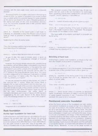
For the foundation shown in Fig 6,
Equivalent concrete Area, Aeq = + m
(Cross sectional area of stub ) (18)
where, m = modular ratio, which may be taken as 18 for M15
concrete. Equivalent moment of inertia about x-x axis,
1 = =+ m . Ira of stub angle (19)
12
= I,/ B, (20)
Position of maximum bending moment in chimney
1- / stn.)1(1+ sat 0]
where, y = weight of soil. If / H3 then I = H3
Now the following check is made:
+ tr,
1.33
a ',+ v a
where, ac = working direct compressive stress,
Crbc = working bending stress.
- A,
( 21 /3 +
cre.,
z
If biaxial bending is there, the bending moment in the other
axis is simply added in the expression for ab, . When equa-
tion (22) is not satisfied, the size of stub is increased or extra
reinforcement is provided.
As shown above, if the stub angle is embedded in the
chimney to its full depth and anchored to The base-slab, the
chimney is treated as a composite member with the stub
angle inside the chimney working as rigid reinforcement.
When the leg of the tower is fixed at the top of the shaft by
anchor bolts, as shown in Fig 1 (b), the shaft is designed for
and reinforced against tension/thrust plus the bending stres-
ses from the moments — uniaxial or biaxial — as the case may
be.
The base slab is designed as per simple bending theory,
i.e., the footing is assumed to behave as a flexural member
cantilevered from the chimney portion. Hence, formulae
commonly used in the design of reinforced concrete flexural
members are made use of in this program4' 10 .
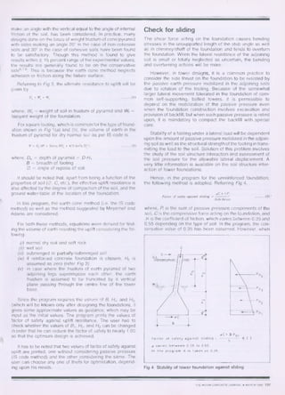
The macro flow chart of this program is shown in Fig 7.
To check the validity of this program, several examples
were worked out by hand and checked with the computer
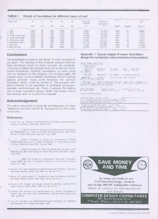
output. A typical output for normal dry soil (unreinforced
foundation) is shown in Appendix I. Details of the founda-
tions for other types of soils for the same compression, ten-
sion and shear are shown in Table 1.
=IP
Fig 7 Macro flow chart of the tower foundation program
(21)
( 22)
(23)
(24)
140 THE INDIAN CONCRETE JOURNAL ♦ MARCH 1990
7. TABLE 1 Details of foundation for different types of soil
Type of soil B H, H2 H3 H,, Concrete Volume of yi 0 UBC
volume excavation
MM mm mm mm mm m3 m3 kg/m3 degree kg/cm2
1. Dry 1450 50 450 2500 225 5.639 37.979 1440 30 2.6800
2. Wet 2050 50 820 2130 225 9.848 68.479 1440 15 1.3675
3. Partly-submerged 2180 50 820 2130 225 10.638 76.265 1440 15 1.3675
4. Fully-submerged 2450 50 1000 1950 225 14.036 93.775 940 15 1.3675
5. Dry black cotton 2150 50 800 2150 225 10.313 74.431 1600 30 1.3675
6. Wet black cotton 3080 50 1350 1600 225 24.775 141.663 1080 0 1.3675
7 Soft rock 1480 50 540 2410 225 6.007 39.288 1440 20 6.2500
8 Wet soft rock 2320 50 950 2000 225 12.586 85.119 1440 10 3.1250
4
Conclusions
The procedures involved in the design of tower foundations
are given. The features of the computer program that has
been developed based on these concepts are explained.
This program takes into account reinforced as well as unrein-
forced foundations. Similarly, foundations on rocks could
also be designed by this program. For resisting uplift, the
program gives a choice between resistance with and without
passive pressure. Using some iterations, the optimum
foundation details could be arrived at. The program also
gives printouts of the quantities of earthwork excavation,
concrete, reinforcement, etc. Thus, it reduces the tedicus
task of tower foundation design, which may involve only a
few seconds work on a personal computer.
Acknowledgement
The authors would like to thank Mr Venkataraman of Indian
Telephone Industries and Mr M. Sundara Raj for the fruitful
discussions.
References
1. KHANNA, R.L. ed., Manual on Transmission Line Towers, Central Board of
Irrigation and Power, New Delhi, March 1977.
2. Code of Practice for Design and Construction of Foundations
for Transmission Line Towers and Poles (First Revision), IS: 4091 - 1979.
Bureau of Indian Standards, New Delhi, July 1980.
3. Code of Practice for Design and Construction of Radar
Antenna, Microwave and TV Tower Foundations, IS: 11233- 1985, Bureau
of Indian Standards, New Delhi, January 1986.
4. Code of Practice for Plain and Reinforced Concrete (Third
Revision), IS: 456-1978, Bureau of Indian Standards, New Delhi, Septe-
mber 1979.
5. . IEEE Trail Guide for Transmission Structures Foundation
Design, IEEE Std. 691, The Institute of Electrical and Electronics Engi-
neers, Inc., 1985.
6. EDwARD. A.T. Uplift resistance of transmission tower footings, Journal of
the Power Division, ASCE, July 1962. Vol. 88, No. Po. 2.
7. DALLAS, I.D., and CHICARZZI, R., Transmission tower foundations, Journal of
the Power Division, ASCE, April 1966. Vol. 92, No. Po. 2.
8. RICHARD, L.W. Analysis and design of tower foundations, Journal of the
Power Division, ASCE, March 1969. Vol. 95, No. Po. 1.
9 CANNON, R.W., GODFREY, D.A. and MOREADITH, F.L., Guide to the design of
anchor bolts and other steel embedments, Concrete International, July
1981, pp 28-41.
10. SyAL, LC., and Goo_ A.K. Reinforced Concrete Structures, A.H. Wheeler
and Company Pvt. Limited, Allahabad, 1984.
Appendix 1 Typical output of tower foundation
design for normal dry soil (unreinforced foundation)
408 KV DOUBLE CIRCUIT SPIC
TOWER DETAILS
TOWER TYPE MAX.THRUST ULT.UPLIFT SHEAR EASE WIDTH
TANGENT 48400 KG 31900 xo 6248 KO 85D CM
SOIL DETAILS
SOIL TYPE COOK-ANOLZ SOIL DENSITY ULT.EIZARING CAPACITY
NORMAL DRY 38 DIG
DETAILS OF NIXIE. FOUNDATION
1 WWI TYPE UPPER 1500 MM NORMAL ORY SOIL LOWER -STRATA SUBMERGED SOIL
• PART-SUBM.TYPZ UPPER 750 MN NORMAL DRY SOIL LOWER STRATA SUBMERGED SOIL
DETAILS OF NORMAL DRY TYPE FOUNDATION
BASE- 1450 MM.S0
DEPTH. 5000 MN PYRAMID HT. 450 MN
PAD THK.. 50 PIM
CHIMNEY WIDTH. 550 MM CHIMNEY HT. 2725 MX
DETAILS OF 1ARTn-PYRAMID
VOLUME OF EARTH 38.96464 CU.ST. WEIGHT. 4 4 519,8 KG
FACTOR OF SAFETY AGAINST UPROOTING OF STUB 3.508476
F.S. AGAINST UPLIFT WITHOUT PASSIVE PRESSURE 1.503844
FACTOR OF SAFETY AGAINST DOWN THRUST 1.004495
VOLUME OF CONCRETE FOR TOWER 5.639 CU.M
VOLUM EARTHWORK EXCAVATION FOR TOWER 37.362 CU.M
MT OF TOTAL STEEL IN FOUNDATION FOR TOWER 0.80 KG
VOLUME OF MAT CONCRETE FOR TOWER 0.612 CU.M
by using our ready to use
Civil Structural Engg. Analysis
and design IBM-PC Compatible Software
Write or contact for free brochures
and details :
COMPUTER DESIGN CONSULTANTS
191, North Usman Road,
T.Nagar, Madras-600 017 Ph:825 0633
1440 KO/CU.MT 26600 KG/SO.MT.
THE INDIAN CONCRETE JOURNAL ♦ MARCH 1990 141