The Radical RXC chassis was designed as a tubular space frame to achieve high torsional stiffness while minimizing weight for improved performance. Triangulation was used in the design to reduce shear forces. The frame material was AISI 1020 steel with Ultimate tensile strength of 420 MPa and yield strength of 350MPa. Finite element analysis showed a maximum deflection of 0.1339mm and von Mises stress of 1.06 x 10⁷ N/m^2 under an applied torque of 410 N-m, yielding a torsional stiffness of 22,043 N-m/deg. While satisfactory, improvements could include optimizing stiffness, reducing weight, addressing buckling risks from low slenderness ratios
The International Journal of Engineering & Science is aimed at providing a platform for researchers, engineers, scientists, or educators to publish their original research results, to exchange new ideas, to disseminate information in innovative designs, engineering experiences and technological skills. It is also the Journal's objective to promote engineering and technology education. All papers submitted to the Journal will be blind peer-reviewed. Only original articles will be published.
The papers for publication in The International Journal of Engineering& Science are selected through rigorous peer reviews to ensure originality, timeliness, relevance, and readability.
Stress Analysis of I.C.Engine Connecting Rod by FEM and PhotoelasticityIOSR Journals
Abstract: The automobile engine connecting rod is a high volume production critical component. Every vehicle
that uses an internal combustion engine requires at least one connecting rod .From the viewpoint of
functionality, connecting rods must have the highest possible rigidity at the lowest weight. The major stress
induced in the connecting rod is a combination of axial and bending stresses in operation. The axial stresses are
produced due to cylinder gas pressure (compressive only) and the inertia force arising in account of
reciprocating action (both tensile as well as compressive), where as bending stresses are caused due to the
centrifugal effects. The result of which is, the maximum stresses are developed at the fillet section of the big and
the small end.Hence, the paper deals with the stress analysis of connecting rod by Finite Element Method using
Pro/E Wildfire 4.0 and ANSYS WORKBENCH 11.0 software. The comparison and verification of the results
obtained in FEA is done experimentally by the method of Photo elasticity(Optical Method). The method of
Photoelasticity includes the casting of Photoelastic sheet using Resin AY103 and Hardner HY951, preparation
of the model from Photoelastic sheet calibration of the sheet to determine material fringe value.
Keywords - Big End fillet section ,Connecting Rod, Compressive Stresses , Failure of Connecting Rod, FEA,
Photoelasticity, Small End fillet section, Tensile Stresses.
CADmantra Technologies Pvt. Ltd. is one of the best Cad training company in northern zone in India . which are provided many types of courses in cad field i.e AUTOCAD,SOLIDWORK,CATIA,CRE-O,Uniraphics-NX, CNC, REVIT, STAAD.Pro. And many courses
Contact: www.cadmantra.com
www.cadmantra.blogspot.com
www.cadmantra.wix.com
This presentation aims to design and analysis of the structure of Hyperloop chassis, which was designed for Hyperloop Pod Building Competition organized by SpaceX 2019.
Stress analysis on steering knuckle of the automobile steering systemeSAT Journals
Abstract Steering Knuckle plays major role in many direction control of the vehicle it is also linked with other linkages and supports the vertical weight of the car. Therefore, it requires high precision, quality, and durability. The main objective of this work is to explore performance opportunities, in the design and production of a steering knuckle. This can be achieved by performing a detailed load analysis. Therefore, this study has been dealt with two steps. First part of the study involves modeling of the steering knuckle with the design parameters using the latest modeling software, and also it includes the determination of loads acting on the steering knuckle as a function of time. This is done for finding out the minimum stress area. Then the stress analysis was performed using analysis software. The steering knuckle can be modeled, and analyzed under the actual load conditions. This may also improve the depth knowledge of its function and performance in terms of durability and quality. Keywords: Steering knuckle, stress analysis and Finite Element Analysis (FEA).
Design analysis of the roll cage for all terrain vehicleeSAT Journals
Abstract We have tried to design an all terrain vehicle that meets international standards and is also cost effective at the same time. We have focused on every point of roll cage to improve the performance of vehicle without failure of roll cage. We began the task of designing by conducting extensive research of ATV roll cage through finite element analysis. A roll cage is a skeleton of an ATV. The roll cage not only forms the structural base but also a 3-D shell surrounding the occupant which protects the occupant in case of impact and roll over incidents. The roll cage also adds to the aesthetics of a vehicle. The design and development comprises of material selection, chassis and frame design, cross section determination, determining strength requirements of roll cage, stress analysis and simulations to test the ATV against failure. Keywords: Roll cage, material, finite element analysis, strength
Finite Element Analysis of Anti-Roll Bar to Optimize the Stiffness of the An...IJMER
The objective of this paper is to analyze the main geometric parameters which affecting the
stiffness of anti-roll bar. Further these parameters are also affecting the body roll angle. By the
optimization of these geometric parameters we can able to increase the stiffness of bar and which will
help to reduce the body roll angle. To calculate the stiffness of anti-roll bar Finite Element software
ANSYS is used. The deflection for the change in internal angle, arm length, moment of inertia, distance
between bushes found by static analysis. To calculate the body roll angle equation used from the
literature survey, however they haven’t taken all the suspension characteristics in the calculation of
moment caused by the suspended and non-suspended masses. The equilibrium condition is considered
between the moments of the force acting on the suspended and non-suspended masses and moments of
reaction of the springs and anti-roll bar used in suspensions. The comparison of different anti-roll bar is
based on the basis of stiffness per weight. The anti-roll bar which having more ratio of stiffness per
weight can be used in the vehicle. As it will improve the stiffness of bar with small increase in weight,
which will result in the improving roll stability of the vehicle.
collision. There are number of wheel test are available in designing of rim to fulfill the safety requirements
and standards. The aim of this study was to analyze and study the structure for car wheel rim by using the
numerical method. The most of the test procedure has to comply with international standards, which establishes
minimum mechanical requirements and impact collision characteristics of wheels. Numerical implementation of
impact test is convenient for shorten the design time and lower development cost. In this study cast aluminium
alloy wheel rim are used for simulation of impact test by using 3–D explicit finite element methods. The design
of aluminium alloy wheel for automobile application which is carried out and paying special attention to
optimization of the shape and mass of the wheel rim according to aesthetical point of view, to overcome the
wheel cap. A finite element model of the wheel with its tire and striker were developed taking account of the
nonlinearity material properties. Simulation was conducted to study the stress and displacement distributions
during impact test. The analyses results are presented as a function of time. The study is carried under the above
constraints and the results are taken to carryout for further analysis i.e. shape and weight optimization of the
wheel.
Connecting Rods are practically generally used in all varieties of automobile engines. Acting as an
intermediate link between the piston and the crankshaft of an engine. It is responsible for transmission of the up
and down motion of the piston to the crankshaft of the engine, by converting the reciprocating motion of the
piston to the rotary motion of crankshaft. Thus, this study aims to carry out for the load, strain and stress analysis
of the crank end of the connecting rod of different materials. Based on which the High Strength Carbon Fiber
connecting rod will be compared with connecting rod made up of Stainless Steel and Aluminum Alloy. The
results can be used for optimization for weight reduction and for design modification of the connecting rod. Pro-E
software is used for modeling and analyses are carried out in ANSYS software. The results archived can also help
us identify the spot or section where chances of failure are high due to stress induced. Also the results obtained
can be used to modify the existing designs so that better performance and longer life cycle can be archived.
Keywords —Connecting Rod, Pro-E, FEA, ANSYS Workbench, Crank, Crankshaft, Piston, Carbon Fiber,
Stainless Steel, Aluminum Alloy.
International Journal of Engineering Research and Applications (IJERA) is an open access online peer reviewed international journal that publishes research and review articles in the fields of Computer Science, Neural Networks, Electrical Engineering, Software Engineering, Information Technology, Mechanical Engineering, Chemical Engineering, Plastic Engineering, Food Technology, Textile Engineering, Nano Technology & science, Power Electronics, Electronics & Communication Engineering, Computational mathematics, Image processing, Civil Engineering, Structural Engineering, Environmental Engineering, VLSI Testing & Low Power VLSI Design etc.
Design and Analysis of Connecting Rod of Diesel Engineijtsrd
The main objective of this study is to review the weight optimization and cost reduction of a connecting rod in a Diesel engine. To get the idea about designing the connecting rod, various stresses to be considered while designing the connecting rod .This has entailed performing a detailed load analysis. The most important factors that are concentrated are stress distribution and deflections. In this project the connecting rod is designed with respect to all the available constraints using advanced cad software CATIA. Later the product file is converted to .stp file format standard exchange of product file and imported to ANSYS workbench to find deformation and analytic valve with respect to the model or product definitions. A. Vijay Kumar | K. Mihir | M. Mrudul | P. Pavan Kumar ""Design and Analysis of Connecting Rod of Diesel Engine"" Published in International Journal of Trend in Scientific Research and Development (ijtsrd), ISSN: 2456-6470, Volume-3 | Issue-3 , April 2019, URL: https://www.ijtsrd.com/papers/ijtsrd23182.pdf
Paper URL: https://www.ijtsrd.com/engineering/mechanical-engineering/23182/design-and-analysis-of-connecting-rod-of-diesel-engine/a-vijay-kumar
Topology Optimization of Gears from Two Wheeler Gear Set Using Parametric StudyIOSRJMCE
: Gears are used to transmit motion from on shaft to another and it has wide variety of applications. One of the applications of gear is in automobile gear box. Gears generally fail when the working stress exceeds the maximum permissible stress. These stresses are proportional to the amount of power transmitted by the gears. This project intends to identify the magnitude of the stresses for a given configuration of a two wheeler gears transmitting power while trying to find ways for reducing weight of the gear. The philosophy for driving this work is the lightness of the gear for a given purpose while keeping intact its functionality thus reducing the material cost of the gear. Ease of incorporating the new feature for weight reduction over the existing process of manufacturing and the magnitude of volume of weight reduced could be considered as the key parameters for assessment for this work.
Design of half shaft and wheel hub assembly for racing carRavi Shekhar
The Half - Shaft and Wheel Hub of Formula One racing car was designed taking into consideration one of the popular model of Redbull racing car. The various dimension of shaft and hub were altered to attain maximum factor of safety.
Analysis of a Drive Shaft for Automobile ApplicationsIOSR Journals
This study deals with optimization of drive shaft using the ANSYS. Substitution of Titanium drive shafts over the conventional steel material for drive shaft has increasing the advantages of design due to its high specific stiffness, strength and low weight. Drive shaft is the main component of drive system of an automobile. Use of conventional steel for manufacturing of drive shaft has many disadvantages such as low specific stiffness and strength. Many methods are available at present for the design optimization of structural systems. This paper discusses the past work done on drive shafts using ANSYS and design and modal analysis of shafts made of Titanium alloy (Ti-6Al-7Nb).
IJRET : International Journal of Research in Engineering and Technology is an international peer reviewed, online journal published by eSAT Publishing House for the enhancement of research in various disciplines of Engineering and Technology. The aim and scope of the journal is to provide an academic medium and an important reference for the advancement and dissemination of research results that support high-level learning, teaching and research in the fields of Engineering and Technology. We bring together Scientists, Academician, Field Engineers, Scholars and Students of related fields of Engineering and Technology.
Design and Fem Analysis of Car Alloy WheelIJERA Editor
The requirements for improved stiffness, reliability, fatigue life and increased efficiency involves challenges of developing innovative design solutions. The present work mainly focus on the design of car alloy wheel, where the analytical and FEM analysis approach was implemented to analyze baseline design. Initially static analysis was performed to obtain total deformation, strain and the stress of car alloy wheel. Three Dimensional model was created using CATIA and FE software ANSYS was used for discretization and analysis to obtain expected solution. The results were obtained through linear static analysis in terms of Total deformation while Minimum principal stress, Max Principal stress were found to be nearly equal for both 6 arms wheel and 4 arms wheel and 22.16 % of reduction in weight was observed and hence overall weight of the car alloy wheel was optimized.
The International Journal of Engineering & Science is aimed at providing a platform for researchers, engineers, scientists, or educators to publish their original research results, to exchange new ideas, to disseminate information in innovative designs, engineering experiences and technological skills. It is also the Journal's objective to promote engineering and technology education. All papers submitted to the Journal will be blind peer-reviewed. Only original articles will be published.
The papers for publication in The International Journal of Engineering& Science are selected through rigorous peer reviews to ensure originality, timeliness, relevance, and readability.
Design mini-project for TY mechanical studentsRavindra Shinde
In these project, we have designed a lifting table suitable to use in college . By adjusting the height of table any student can have proper sitting posture and position. It is also helpful for programmers/coders who have to seat for a long time, by having such a table they can do coding in a standing position too.
1. Radical RXC Chassis Report
Overview- The tubular space frame for Radical RXC was designed keeping in mind to achieve
high torsional stiffness with minimum weight to get an overall better performance of the
race car.
Brief Literature review- While designing space frame for Radical RXC rule of triangulation
was kept in mind as it allows only tensile and compressive stresses to be transmitted
through tubes and reducing the possibility of shear forces which is undesirable for a space
frame structure.
The material used in designing process is AISI 1020 steel( cold rolled) having Ultimate
tensile strength – 420 Mpa and yield strength – 350Mpa which is desirable for space frame
chassis subjected to torsional and bending forces.
A space frame is strong because of the inherent rigidity of the triangle; flexing loads
(bending moments) are transmitted as tension and compression loads along the length of
each strut. Also it was decided to keep slenderness ratio (L/K) of each tube to be greater
than 10.The wheelbase of the car was assumed to be 1770 mm and front and rear track
width as 820 mm. The thickness of the tubes that were used was:
Roll Hoops – 40 x 2.5 mm
Side Impact and front bulkhead – 40 x 2 mm
Triangulation tubes – 25 x 2 mm
*These tube dimensions were decided after having relative knowledge of tube dimensions of FSAE
space frames.
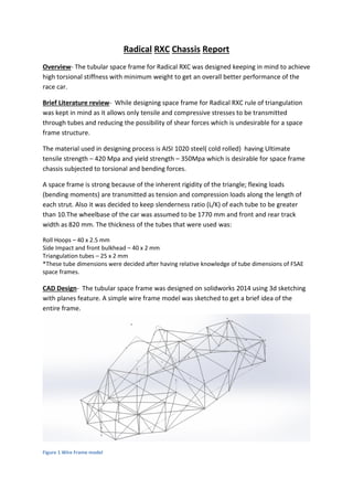
CAD Design- The tubular space frame was designed on solidworks 2014 using 3d sketching
with planes feature. A simple wire frame model was sketched to get a brief idea of the
entire frame.
Figure 1 Wire Frame model
2. Weldments of required dimensions were added to the wire model and were profiled using trim and
extend feature of solidworks.
Figure 2 Frame CAD model
Finite element analysis(FEA)- The FEA of this space frame was done using solidworks 2014
simulation tool. Simple torsional test was performed on the frame by applying equal and opposite
torques on front wheel centres. An equal and opposite force of 500N was applied on front wheel
centres keeping the rear hard points constrained.
Figure 3 Static displacement plot
3. Figure 4 Static Stress plot( Von Mises stress)
Torsional stiffness calculation:
F : Force applied
Τ : Applied Torque
d : Distance between wheel centres
δ : Deflection of wheel centre
φ : Angular deflection of wheel centre
d= 820mm = 0.82m
For left wheel:
δL = 0.1339mm
φL= (Deflection ofleft wheel centre)/(Distance of left wheel centre from vehicle centreline)
= (δL )/(d/2)
= 0.1339mm⁄410 mm = 3.26 x 10^-4 rad = 0.0186 degree
For right wheel:
δR = 0.1336 mm
φR = (δR )/(d/2) = 0.1336⁄410mm= 3.26 x 10^-4 rad = 0.0186
φav = (φL + φR)/2 = 0.0186 °
4. Torque applied, Τ = F x d = 500 x 0.82 = 410 N-m
Torsional Stiffness = Τ / φav = 410 N-m / 0.0186 ° = 22,043 N-m/deg.
Results-
Maximum deflections of 0.1339mm found in the frame at nodes where opposite forces
were applied. A von Mises stress plot was also plotted as shown in the figure above and
maximum stress was found to be 1.06 x 10⁷ N/m^2 which was found to be satisfactory
considering the design requirements.
The torsional stiffness of the frame as calculated is 22,043 N-m/deg which is very much
desirable for a high performance sports car.
Suggested Improvements-
1. Choosing appropriate target value of torsional stiffness. The torsional rigidity of
frame currently is very high which should be in range of 17,000 to 21,000N-m/deg.
2. Reduction in weight by reducing tube dimensions of proper UTM testing, this will
also reduce torsional stiffness and increase overall performance of the sports car.
3. Some tubes in frame have slenderness ratio < 10 which can cause buckling which is
not desirable in a high performance sports car.
4. Ergonomic factors were not considered which also plays a vital role and affects
performance of a sports car.
5. Having properly constructed hard points could have been beneficial in designing
process of the space frame keeping aesthetics under consideration.
Conclusion-
The overall performance can be considered satisfactory but can be increased by performing
more weight saving operations. As assembly of different components were not taken into
consideration, the stiffest parts of the frame could not be determined.