Downloaded 949 times

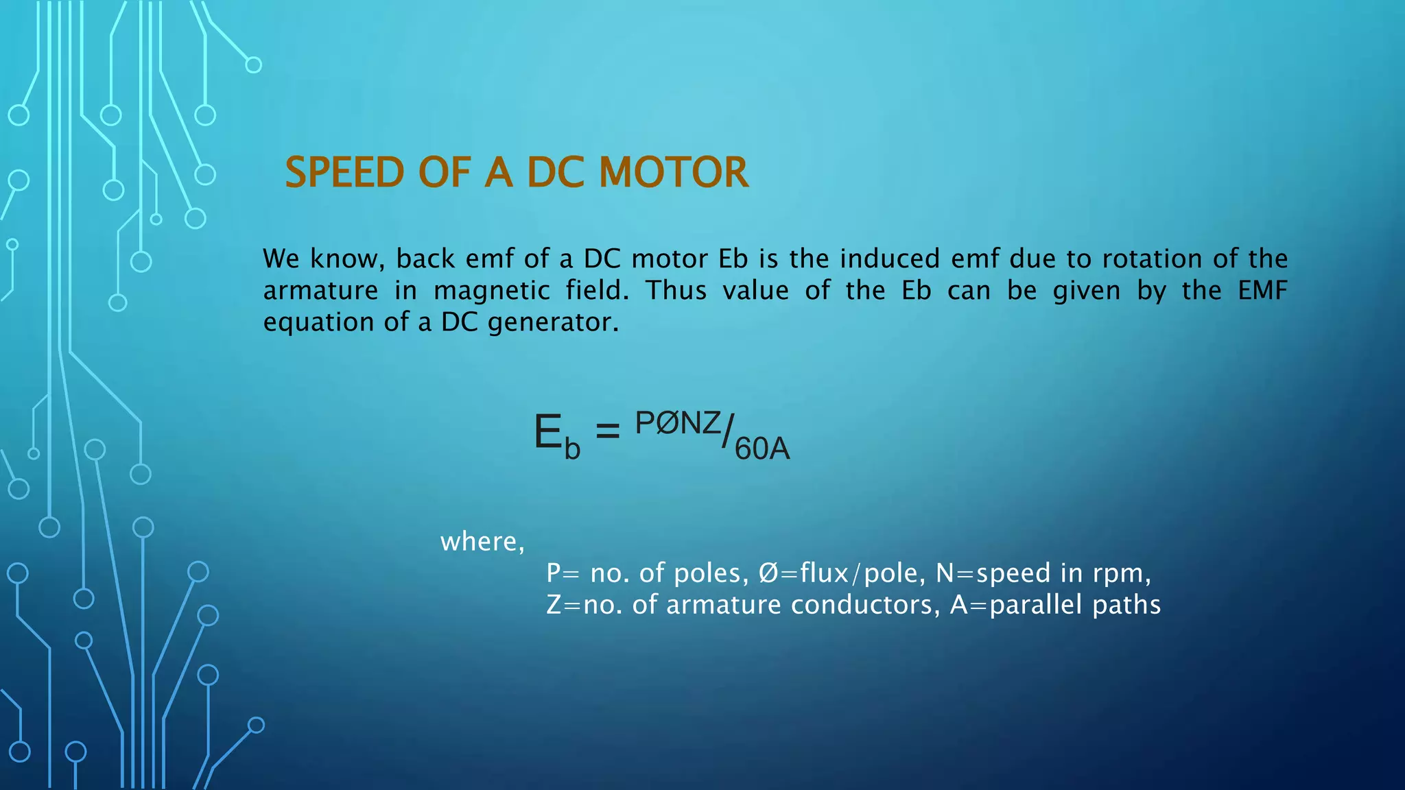
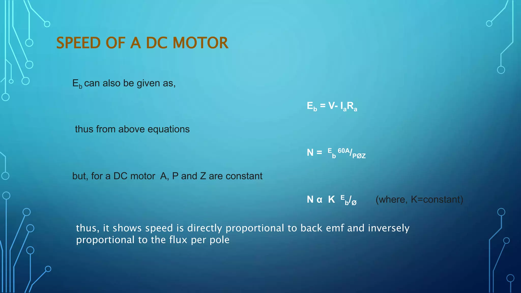

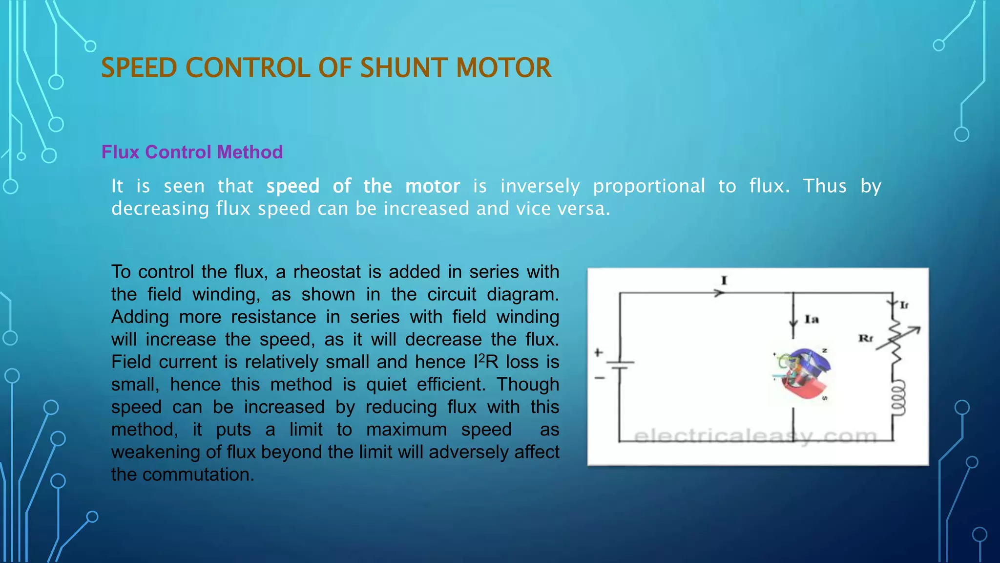

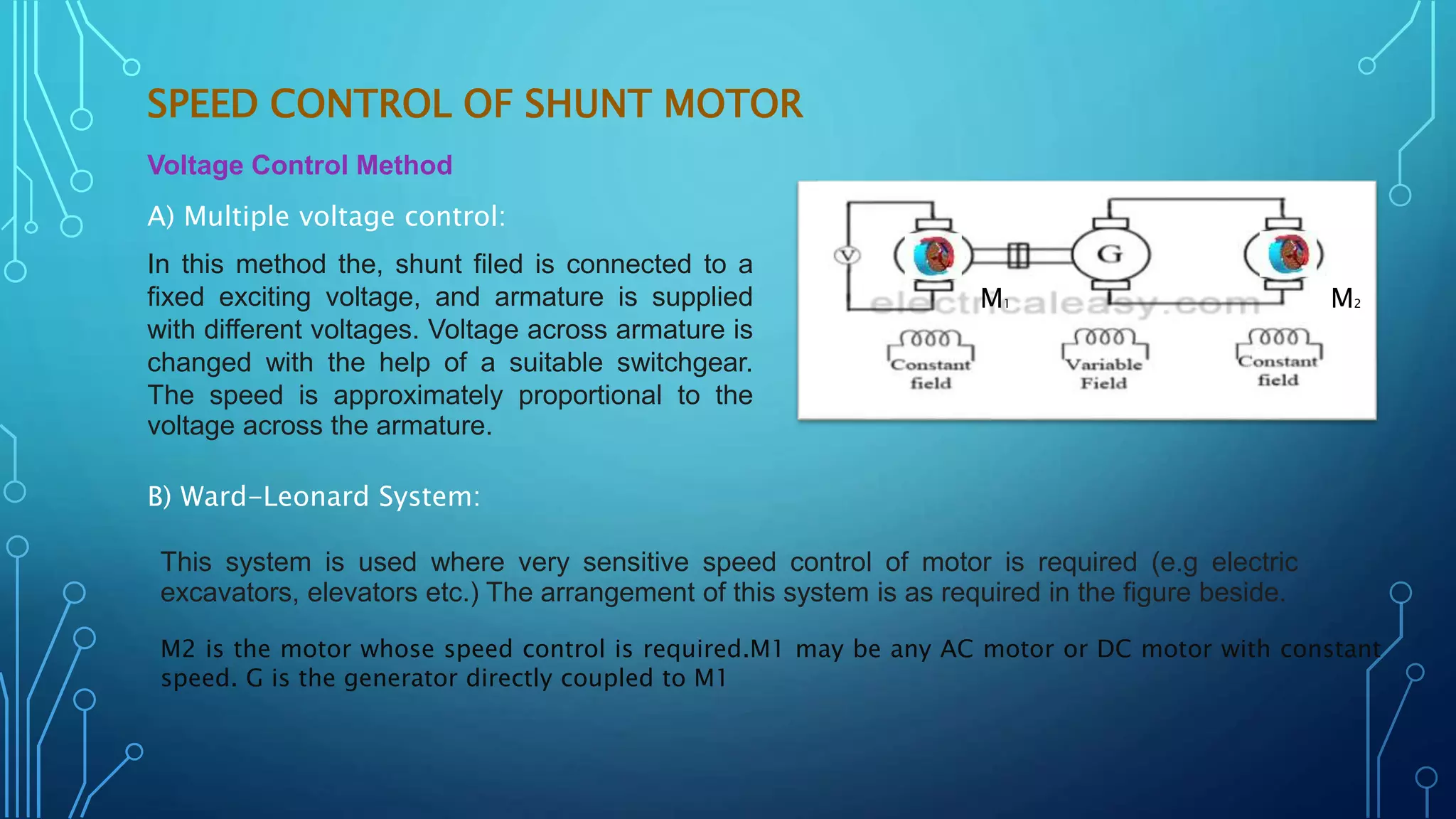
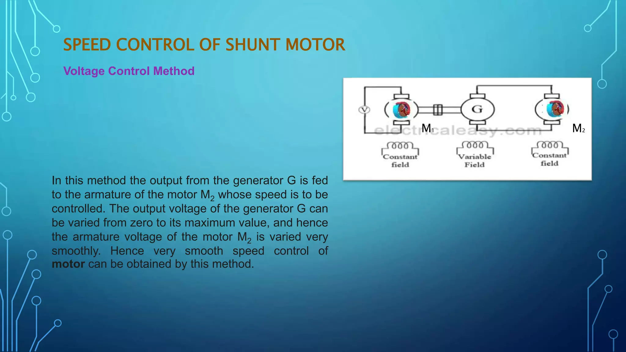
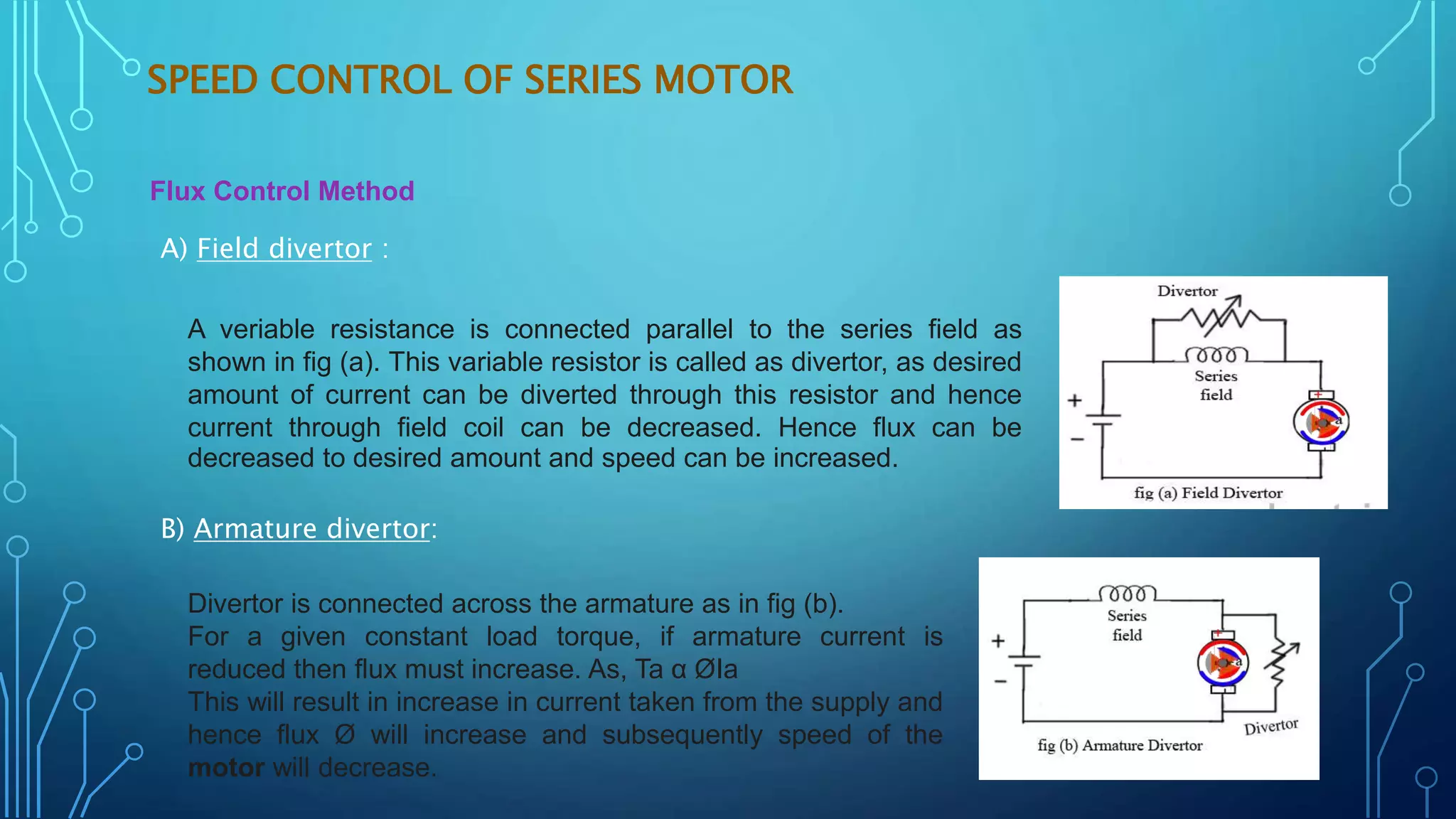
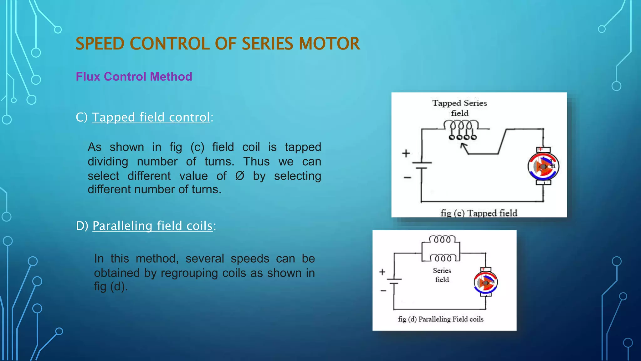


This document discusses various speed control methods for DC motors. It summarizes that the speed of a DC motor is directly proportional to the back EMF and inversely proportional to flux. For shunt motors, speed can be controlled through flux control by adding resistance to the field winding, armature control by adding resistance in series to the armature, and voltage control by varying the supply voltage. For series motors, speed is controlled through flux control methods like field and armature diversion, tapped fields, and paralleled fields as well as adding resistance in series with the armature. Series-parallel control is also described for variable speed applications.


