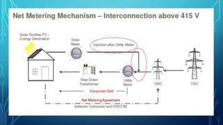
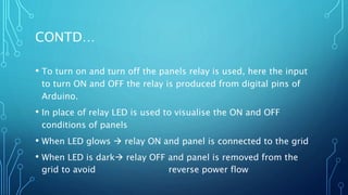
REVERSE POWER RELAY FOR
ROOFTOP SOLAR PV SYSTEM
Guided by,
Dr.T.Bogaraj.
Done by,
C.Balaji 15E105
J.Karthickraja 15E117
S.Praveenkumar 15E137
S.Boopalan 16E402
WHAT IS REVERSE POWER RELAY?
• A reverse power relay is a relay that prevents power from flowing in
the reverse direction.
• Normally, it is used when a generator runs in parallel with another
generator in order to prevent the power from the bus bar or another
generator from flowing back to the active generator when its output
fails.
• The relay monitors the power from the generator continuously and
when the generator output falls below a preset value, it quickly
disconnects the generator coil.
ROOFTOP SOLAR PANELS
• Off-Grid
• The excess power produced by the solar panels is wasted.
• Grid connected
• Net Metering – A bi-directional electricity meter is used to calculate the
difference between load consumed and the power fed into the grid.
• Gross Metering – Two meters are used, one for load consumed and one
for power fed into the grid.
• The main disadvantage is cost.
OUR OBJECTIVE
• To design a reverse power relay which disconnects the panels
from the grid when the load consumed falls below a particular
fraction of the “maximum power delivered by the solar panels”
and to reconnect the panels when the load consumed is above
the above the particular fraction.
• The maximum solar output is definitely not constant, but
changes with respect to a lot of factors.
THE SCENARIO
• The load consumed during weekends and holidays is very less.
If it becomes less than the solar output, power flows in the
reverse direction during those days. The absence of net
metering means that our college management is paying for the
power fed into the grid additionally.
2180
2849.4
6437
6587.6
5348.1
9403.2
5792.9
3512.7
9692
10061.6
9654.2
10195.1
9272.3
8592.4
3502.6
7542.6
3522.9
2459.7
4143.1
6874.5
4530.1
3182.1
6276.2
5412.8
3795
6292.1
7087.8
7081.2
3034.2
6586
7482.4
1 2 3 4 5 6 7 8 9 10 11 12 13 14 15 16 17 18 19 20 21 22 23 24 25 26 27 28 29 30 31
UNITSINKWH
DAYS
INCOMING EB DETAILS FOR OCT 2017
HOW ARE WE GOING TO DO?
• The load consumed during every instant has to be known.
• In order to generate the control signal to make/break the
contact, a microcontroller has to be used.
• So, the continuous analog data has to be converted into digital
data.
• But, the data is available as digital data.
• The data has to be interfaced with the microcontroller.
THE STRATEGY
• The simplest way is to always consume a fixed fraction of the
load from the grid so that power will not reverse its direction.
• If the load consumed is more than the total solar output, there
is no problem at all.
• If the load consumed is less than the total solar output,
depending on the load, a number of panels will be
disconnected.
RELAY
• The selection of relay is important.
• A single pole single throw relay or a single three pole single
throw relay can be chosen.
• A SPST relay will be cost efficient.
• The microcontroller output should be able to drive the relay
otherwise, additional circuitry is required which adds to the
cost.
• The relay need not respond instantaneously.
WHERE IT CAN BE USED?
• In places where there is a grid connected PV system, which
cannot afford the net metering facility. (Places which already
have a grid connected system.)
• In places where net metering facility fails.
SIMULATION
OUR SIMULATION
• We have accounted 5 panels neglecting the drops in individual
panels it is assumed that each panel produces same output as
other
• The power demanded by load and produced by the solar are
realised by using the potentiometers
• By varying this POT we can realise various demand and supply
conditions and link with real time scenarios.
• SAMPLING of the power can be controlled through program
CONTD…
• To turn on and turn off the panels relay is used, here the input
to turn ON and OFF the relay is produced from digital pins of
Arduino.
• In place of relay LED is used to visualise the ON and OFF
conditions of panels
• When LED glows  relay ON and panel is connected to the grid
• When LED is dark relay OFF and panel is removed from the
grid to avoid reverse power flow
• Assumptions
• Voltage - more or less constant
• Power factor - (close to unity)
• By assuming these the estimated output will be around ±5%
erroneous
• But it greatly reduces cost.
• The power is sampled at each instant and brought up for
computation
• The output of POT is connected to analog port and it is
converted into its equivalent digital value and noted in serial
monitor
• In the above mentioned way the simulation is done by
• Setting pot1(solar) to required value and
• Setting pot2(load) to change from(5-0) and the expected output is
observed for each condition tabulated above.
• The accuracy can be further improved by perfect computations
and increasing the ranges of power samples.
OUR SCENARIO
Power
consumed
by load in
(%)
Panels
operating at
rated power
To avoid reverse flow of power into grid a small
% of power is consumed from the grid.
>90 5 ON
90-80 4 ON
60-80 3 ON
40-60 2 ON
20-40 1ON
0-20 ALL OFF
Power produced by solar
FOR EASY UNDERSTANDING
Power
consumed by
load
Panels
operating at
rated power(5)
>5 5 ON
3.5-5 4 ON
2.5-3.5 3 ON
2.5-3.5 2 ON
1.25-2.5 1ON
0-1.25 ALL OFF
5 panels – 5A (each1A)
1)MAX demand-
5A*230
produced-5A*230
panels on-4
so, remaining 1A*230
from grid
Thank You!!

Reverse power relay

  • 1.
    REVERSE POWER RELAYFOR ROOFTOP SOLAR PV SYSTEM
  • 2.
    Guided by, Dr.T.Bogaraj. Done by, C.Balaji15E105 J.Karthickraja 15E117 S.Praveenkumar 15E137 S.Boopalan 16E402
  • 3.
    WHAT IS REVERSEPOWER RELAY? • A reverse power relay is a relay that prevents power from flowing in the reverse direction. • Normally, it is used when a generator runs in parallel with another generator in order to prevent the power from the bus bar or another generator from flowing back to the active generator when its output fails. • The relay monitors the power from the generator continuously and when the generator output falls below a preset value, it quickly disconnects the generator coil.
  • 4.
    ROOFTOP SOLAR PANELS •Off-Grid • The excess power produced by the solar panels is wasted. • Grid connected • Net Metering – A bi-directional electricity meter is used to calculate the difference between load consumed and the power fed into the grid. • Gross Metering – Two meters are used, one for load consumed and one for power fed into the grid. • The main disadvantage is cost.
  • 5.
    OUR OBJECTIVE • Todesign a reverse power relay which disconnects the panels from the grid when the load consumed falls below a particular fraction of the “maximum power delivered by the solar panels” and to reconnect the panels when the load consumed is above the above the particular fraction. • The maximum solar output is definitely not constant, but changes with respect to a lot of factors.
  • 6.
    THE SCENARIO • Theload consumed during weekends and holidays is very less. If it becomes less than the solar output, power flows in the reverse direction during those days. The absence of net metering means that our college management is paying for the power fed into the grid additionally.
  • 7.
  • 10.
    HOW ARE WEGOING TO DO? • The load consumed during every instant has to be known. • In order to generate the control signal to make/break the contact, a microcontroller has to be used. • So, the continuous analog data has to be converted into digital data. • But, the data is available as digital data. • The data has to be interfaced with the microcontroller.
  • 11.
    THE STRATEGY • Thesimplest way is to always consume a fixed fraction of the load from the grid so that power will not reverse its direction. • If the load consumed is more than the total solar output, there is no problem at all. • If the load consumed is less than the total solar output, depending on the load, a number of panels will be disconnected.
  • 12.
    RELAY • The selectionof relay is important. • A single pole single throw relay or a single three pole single throw relay can be chosen. • A SPST relay will be cost efficient. • The microcontroller output should be able to drive the relay otherwise, additional circuitry is required which adds to the cost. • The relay need not respond instantaneously.
  • 13.
    WHERE IT CANBE USED? • In places where there is a grid connected PV system, which cannot afford the net metering facility. (Places which already have a grid connected system.) • In places where net metering facility fails.
  • 14.
  • 15.
    OUR SIMULATION • Wehave accounted 5 panels neglecting the drops in individual panels it is assumed that each panel produces same output as other • The power demanded by load and produced by the solar are realised by using the potentiometers • By varying this POT we can realise various demand and supply conditions and link with real time scenarios. • SAMPLING of the power can be controlled through program
  • 17.
    CONTD… • To turnon and turn off the panels relay is used, here the input to turn ON and OFF the relay is produced from digital pins of Arduino. • In place of relay LED is used to visualise the ON and OFF conditions of panels • When LED glows  relay ON and panel is connected to the grid • When LED is dark relay OFF and panel is removed from the grid to avoid reverse power flow
  • 18.
    • Assumptions • Voltage- more or less constant • Power factor - (close to unity) • By assuming these the estimated output will be around ±5% erroneous • But it greatly reduces cost. • The power is sampled at each instant and brought up for computation
  • 19.
    • The outputof POT is connected to analog port and it is converted into its equivalent digital value and noted in serial monitor • In the above mentioned way the simulation is done by • Setting pot1(solar) to required value and • Setting pot2(load) to change from(5-0) and the expected output is observed for each condition tabulated above. • The accuracy can be further improved by perfect computations and increasing the ranges of power samples.
  • 20.
    OUR SCENARIO Power consumed by loadin (%) Panels operating at rated power To avoid reverse flow of power into grid a small % of power is consumed from the grid. >90 5 ON 90-80 4 ON 60-80 3 ON 40-60 2 ON 20-40 1ON 0-20 ALL OFF Power produced by solar
  • 21.
    FOR EASY UNDERSTANDING Power consumedby load Panels operating at rated power(5) >5 5 ON 3.5-5 4 ON 2.5-3.5 3 ON 2.5-3.5 2 ON 1.25-2.5 1ON 0-1.25 ALL OFF 5 panels – 5A (each1A) 1)MAX demand- 5A*230 produced-5A*230 panels on-4 so, remaining 1A*230 from grid
  • 22.