Downloaded 20 times
![Mathematical Modelling of PV Module With multilevel 3-Ø inverter using SPWM technique for grid application
www.iosrjournals.org 44 | Page
Mathematical modelling of PV module is being continuously updated to enable researcher to have a
better understanding of its working [1-6].In this paper, a step-by-step procedure for simulating PV module with
simple subsystem blocks, with user-friendly icons and dialog in the same way as Matlab/ Simulink block
libraries is developed. The step-by-step modelling procedure of PV module as well as DC/DC converter, PWM
inverter through connected to Grid is presented with simulation results for different conditions of irradiation.
Photovoltaic systems require interfacing power converters between the PV arrays and the grid. These
power converters are used for two major tasks. First, to ensure that the PV arrays are operated at the maximum
power point (MPPT) [2-7]. Second, to inject a sinusoidal current into the grid. Normally there are two power
converters [8]. The first one is a DC/DC power converter. that is used to operate the PV arrays at the maximum
power point. The other one is a DC/AC power converter to interconnect the photovoltaic system to the grid. The
classical single or three-phase two level voltage source inverter is normally used for this power converter type
[9-12]. However, other topologies have been proposed. Multilevel converter topologies are a very interesting
choice for realizing this objective.
There are several PV system configurations. These configurations are the centralized technology, string
technology, multi-string technology and AC-module technology. The number and type of power converters that
is used to interconnect the PV system to the grid is dependent of the technology that is used. The multi-string
technology has several different groups of PV arrays. Each group is connected in series with a DC/DC
converter. This allows using this technology with some multilevel topologies, such as, the cascaded multicell
inverters. This topology is based on the series connection of single-phase inverters with separated DC sources.
In this way, each group of PV arrays will be used as a single DC source. This allows avoiding high voltage
amplification. In order to obtain a galvanic connection between the grid and the PV generator many PV systems
use a power transformer, avoiding that a leakage current may flow through the capacitance between PV
generator and ground. Some systems use a transformer embedded in a high-frequency DC/DC converter. Others
use a line frequency transformer at the output of the inverter.
Fig.2 PV modules connected to grid via Multilevel inverter
This mechanism proposes a three -phase multistring five-level inverter topology. It consists of three
strings of PV arrays connected to their own dc–dc boost converter. An auxiliary circuit comprising four diodes
and a switch is configured together with a conventional full-bridge inverter to form this topology. A SPWM
control scheme is introduced to generate switching signals for the switches and to produce five output-voltage
levels: zero, +1/2Vdc, Vdc, -1/2Vdc, and -Vdc (assuming that Vdc is the supply voltage). This inverter topology
uses two reference signals instead of one to generate PWM signals for the switches. Both reference signals
Vref1 and Vref2 are identical to each other, except for an offset value that is equivalent to the amplitude of
carrier signal Vcarrier. Because the inverter is used in a PV system, a proportional–integral (PI) current control
scheme is employed to keep the output current sinusoidal and to have high dynamic performance under rapidly
changing atmospheric conditions and to maintain the power factor at near unity. Simulation and experimental
results are presented to validate the proposed inverter configuration.
II. Mathematical Model For Pv Module
A solar cell is basically a p-n junction fabricated in a thin wafer of semiconductor. The electromagnetic
radiation of solar energy can be directly converted to electricity through Photovoltaic effect. Being exposed to
the sunlight, photons with energy greater then the band-gap energy of the semiconductor creates some electron-
hole pairs proportional to the incident irradiation.
Fig.3: Equivalent diagram of PV cell](https://image.slidesharecdn.com/f0844353-140508020105-phpapp01/75/Mathematical-Modelling-of-PV-Module-With-multilevel-3-O-inverter-using-SPWM-technique-for-Grid-application-2-2048.jpg)
![Mathematical Modelling of PV Module With multilevel 3-Ø inverter using SPWM technique for grid application
www.iosrjournals.org 45 | Page
A model of PV module with moderate complexity that includes the temperature independence of the
photocurrent source, the saturation current of the diode, and a series
Resistance is considered based on the Shockley diode equation.
The current source Iph represents the cell photocurrent. Rsh and Rs are the intrinsic shunt and series
resistances of the cell, respectively. Usually the value of Rsh is very large and that of Rs is very small, hence
they may be neglected to simplify the analysis. PV cells are grouped in larger units called PV modules which
are further interconnected in a parallel-series configuration to form PV arrays.
The photovoltaic panel can be modelled mathematically as given in equations (1)- (4) [3] – [5]. Module photo-
current:
𝐼𝑝 = 𝐼𝑆 𝐶𝑟 + 𝐾𝑖 𝑇 − 298 ∗
𝜆
1000
(𝑖)
Modules reverse saturation current - Irs:
𝐼𝑟𝑠 = 𝐼𝑆𝐶𝑟 /[exp
𝑞𝑉𝑂𝐶
𝑁𝑠 𝑘𝐴𝑇
− 1] (𝑖𝑖)
The module saturation current I0 varies with the cell temperature, which is given by
𝐼 𝑂 = 𝐼𝑟𝑠
𝑇
𝑇𝑟
∗ [exp
𝑞 ∗ 𝑉𝑔𝑜
𝐵𝑘
1
𝑇𝑟
−
1
𝑇
− 1] (𝑖𝑖𝑖)
The current output of PV module is
𝐼 𝑃𝑉 = 𝑁𝑃 ∗ 𝐼𝑝 − 𝑁𝑃 ∗ 𝐼𝑜 [exp
𝑞 ∗ (𝑉𝑃𝑉 + 𝐼 𝑃𝑉 𝑅𝑆
𝑁𝑆 𝐴𝑘𝑇
− 1] (𝑖𝑣)
Where Vpv = Voc, Np = 1 and Ns = 36
PV module represents the fundamental power conversion unit of a PV generator system. The output
characteristics of a PV module depend on the solar insolation, the cell temperature and the output voltage of the
PV module. Since PV module has nonlinear characteristics, it is necessary to model it for the design and
simulation of maximum power point tracking (MPPT) for PV system applications.
The above mentioned equations are modelled by using common Simulink blocks as shown below fig:3
a. Subsystem 1 is shown in Figure 4. This model converts the module operating temperature given in degrees
Celsius to Kelvin.
b. subsystem 2 This model calculates the short circuit current ( ISC) at given operating temperature. Figure 4
gives the circuit under subsystem.
c. Subsystem 3 is shown in Figure 4. This model takes short circuit current ISC at reference temp. = 2.55A and
Module reference temperature TrK = 25oC as input.
d. Subsystem 4 This model takes reverse saturation current Irs, Module reference temperature TrK = 250 C and
Module operating temperature TaK as input and calculates module saturation current.
e. This model takes operating temperature in Kelvin TaK and calculates the product NsAkT, the denominator of
the exponential function in equation (4).
f. This model executes the function given by the equation (4). The following function equation is used. This
gives the circuit under subsystem 6.
IPV = u(3)-u(4)*(exp((u(2)*(u(1)+u(6)))/(u(5)))-1)
All the above six subsystem models are interconnected in such a way that to produce PV current at
corresponding voltage.
Fig.4 Interconnected Simulink model for all equations sub systems](https://image.slidesharecdn.com/f0844353-140508020105-phpapp01/75/Mathematical-Modelling-of-PV-Module-With-multilevel-3-O-inverter-using-SPWM-technique-for-Grid-application-3-2048.jpg)
![Mathematical Modelling of PV Module With multilevel 3-Ø inverter using SPWM technique for grid application
www.iosrjournals.org 46 | Page
The final model takes irradiation; operating temperature in Celsius and module voltage as input and gives the
output current Ipv and output voltage Vpv and Rated Power Ppv.The workspace is added to measure Ipv, Vpv,
and Ppv in this model.
III. Modelling Of Multistring Five-Level Inverter Topology
The proposed Three-phase multistring five-level inverter topology is shown in Fig. 5. It consists of three
dc–dc boost converters connected to a common dc bus, an auxiliary circuit, and a full-bridge inverter
configuration. Input sources, PV string 1, PV string 2, and PV string 3 are connected to the inverter via the dc–
dc boost converters. Because the proposed inverter is used in a grid-connected PV system, the utility grid is used
instead of a load. The dc–dc boost converters are used to track the maximum power point (MPP) independently
and to step up inverter output voltage Vinv to be more than √2 of grid voltage Vg to ensure power flow from the
PV arrays into the grid [12].
𝑉𝑖𝑛 > 2
𝑉𝑔
2𝑉 𝑖𝑛
(v)
The dc–dc boost converters are connected in parallel to avoid high dc-bus voltage, which will eventually
increase the size of the capacitors and the inverter’s cost. Therefore, only two capacitors with equal capacitance
rating are used as the dc bus, and the other dc–dc boost converters are connected to this dc bus, as shown in Fig.
5.
Fig.5: Proposed approach of multilevel inverter
Fig.6: Equivalent model of Pv module connected to grid
A filtering inductance Lf is used to filter the current injected into the grid. The injected current must be
sinusoidal with low harmonic distortion. In order to generate sinusoidal current, a sinusoidal PWM is used
because it is one of the most effective methods. A sinusoidal PWM is obtained by comparing a high frequency
carrier signal with a low-frequency sinusoid signal, which is the modulating or reference signal. The carrier has
PV MODULE DC/DC
CONVERTER
LOAD/GRID
PWM
GENERATOR
PI
CONTROLLER](https://image.slidesharecdn.com/f0844353-140508020105-phpapp01/75/Mathematical-Modelling-of-PV-Module-With-multilevel-3-O-inverter-using-SPWM-technique-for-Grid-application-4-2048.jpg)
![Mathematical Modelling of PV Module With multilevel 3-Ø inverter using SPWM technique for grid application
www.iosrjournals.org 47 | Page
a constant period; therefore, the switches have constant switching frequency. The switching instant is
determined from the crossing of the carrier and the modulating signal.
Modulation index Ma for a five-level PWM inverter is given as [13-14]
𝑀𝑎 =
𝐴 𝑚
2𝐴 𝑐
(vii)
where Ac is the peak-to-peak value of carrier and Am is the peak value of voltage reference Vref . Because, in
this paper, two reference signals that are identical to each other are used, (vii) can be expressed in terms of the
amplitude of carrier signal Vc by replacing Ac with Vc, and Am = Vref1 = Vref2 = Vref
.
𝑀 =
𝑉𝑟𝑒𝑓
2𝑣𝑐
(𝑣𝑖𝑖𝑖)
From the PWM modulation, the analysis of harmonic components in the proposed inverter can be preformed.
The output voltage produced by comparison of the two reference signals and the carrier signal can be expressed
as [7]
𝑉0 𝜃 = 𝐴0 + (𝐴 𝑛 𝑐𝑜𝑠𝑛𝜃 + 𝐵𝑛 𝑠𝑖𝑛𝑛𝜃)
∞
𝑛=1
(𝑖𝑥)
If there are P pulses per quarter period, and it is an odd number, coefficients Bn and Ao would be zero, where n
is an even number. Therefore, the (ix) can be rewritten as
𝑉0 𝜃 = 𝐴 𝑛 𝑐𝑜𝑠𝑛𝜃
∞
𝑛=1
(𝑥)
𝐴 𝑛 = −
2𝑉 𝑑𝑐
𝑛𝜋
[(−1)𝑖𝑛𝑡 (
𝑖
2
)4
𝑖=1
𝑃
𝑚=0 sin(𝑛𝛼 𝑚+𝑖)] (𝑥𝑖)
Fig.7: carrier and reference signal for modulation index M=0.5
where m is a pulse number and α is the phase displacement angle. The Fourier series coefficients of the
conventional single phase full-bridge inverter by sinusoidal PWM is given as
𝐴 𝑛 = −
𝑉𝑑𝑐
𝑛𝜋
[ −1 𝑚
𝑝
𝑚=1
sin(𝑛𝛼 𝑚 )] (𝑥𝑖𝑖)
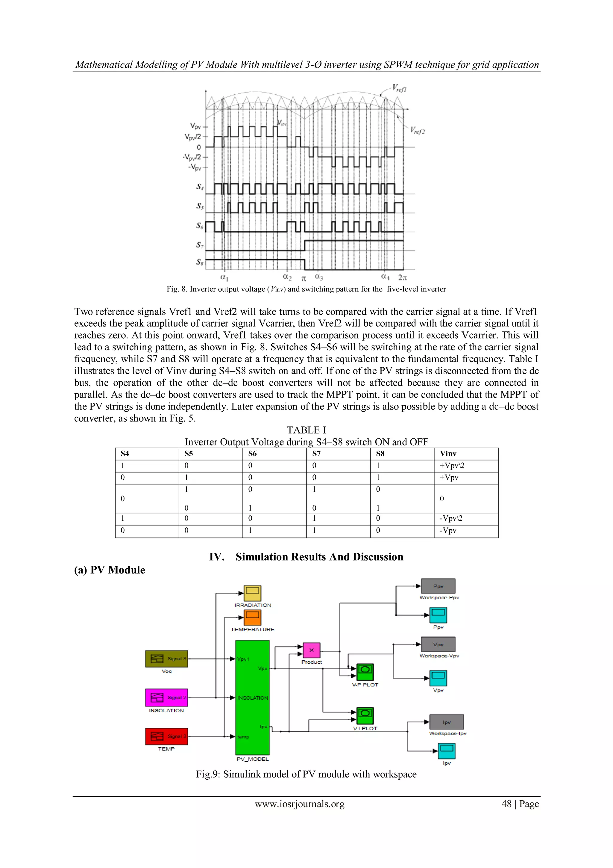
Combinations of PV strings are used as the input voltage sources. The voltage across the strings are known as
Vpv1, Vvp2, and Vpv3. Referring to (1) and (2), Vpv1, Vvp2, and Vvp3 are boosted by the dc–dc boost
converters to exceed grid voltage Vg, and the voltage across the dc bus is known as Vpv. The operating principle
of the proposed inverter is to generate five output-voltage levels, i.e., 0, +Vpv/2, +Vpv, −Vpv/2, −Vpv, as in Fig.
8. As shown in Fig. 5, an auxiliary circuit that consists of four diodes and a switch S4 is used between the dc-
bus capacitors and the full-bridge inverter. Proper switching control of the auxiliary circuit can generate half
level of PV supply voltage, i.e., +Vpv/2 and -Vpv/2 [15-17].](https://image.slidesharecdn.com/f0844353-140508020105-phpapp01/75/Mathematical-Modelling-of-PV-Module-With-multilevel-3-O-inverter-using-SPWM-technique-for-Grid-application-5-2048.jpg)
![Mathematical Modelling of PV Module With multilevel 3-Ø inverter using SPWM technique for grid application
www.iosrjournals.org 52 | Page
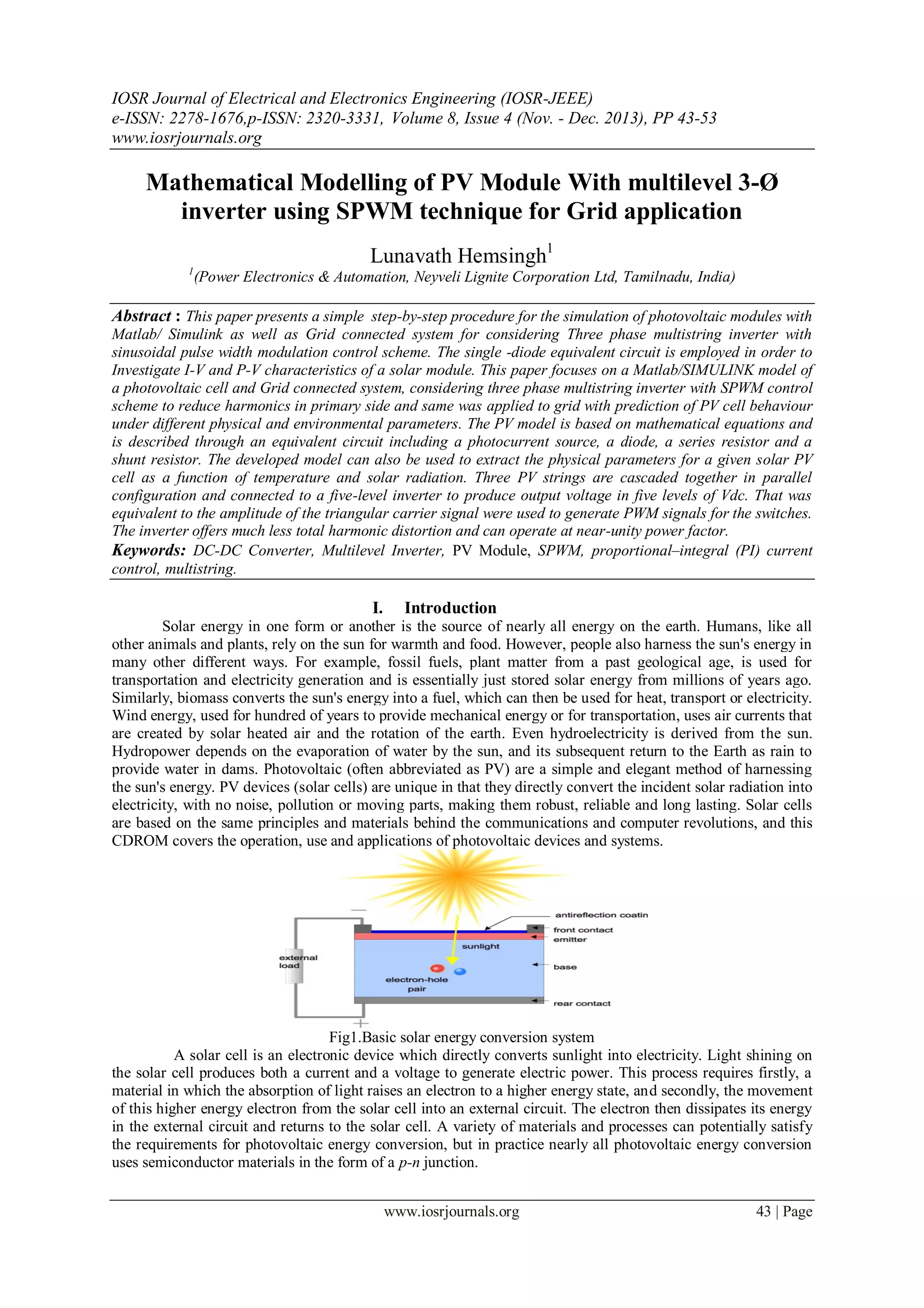
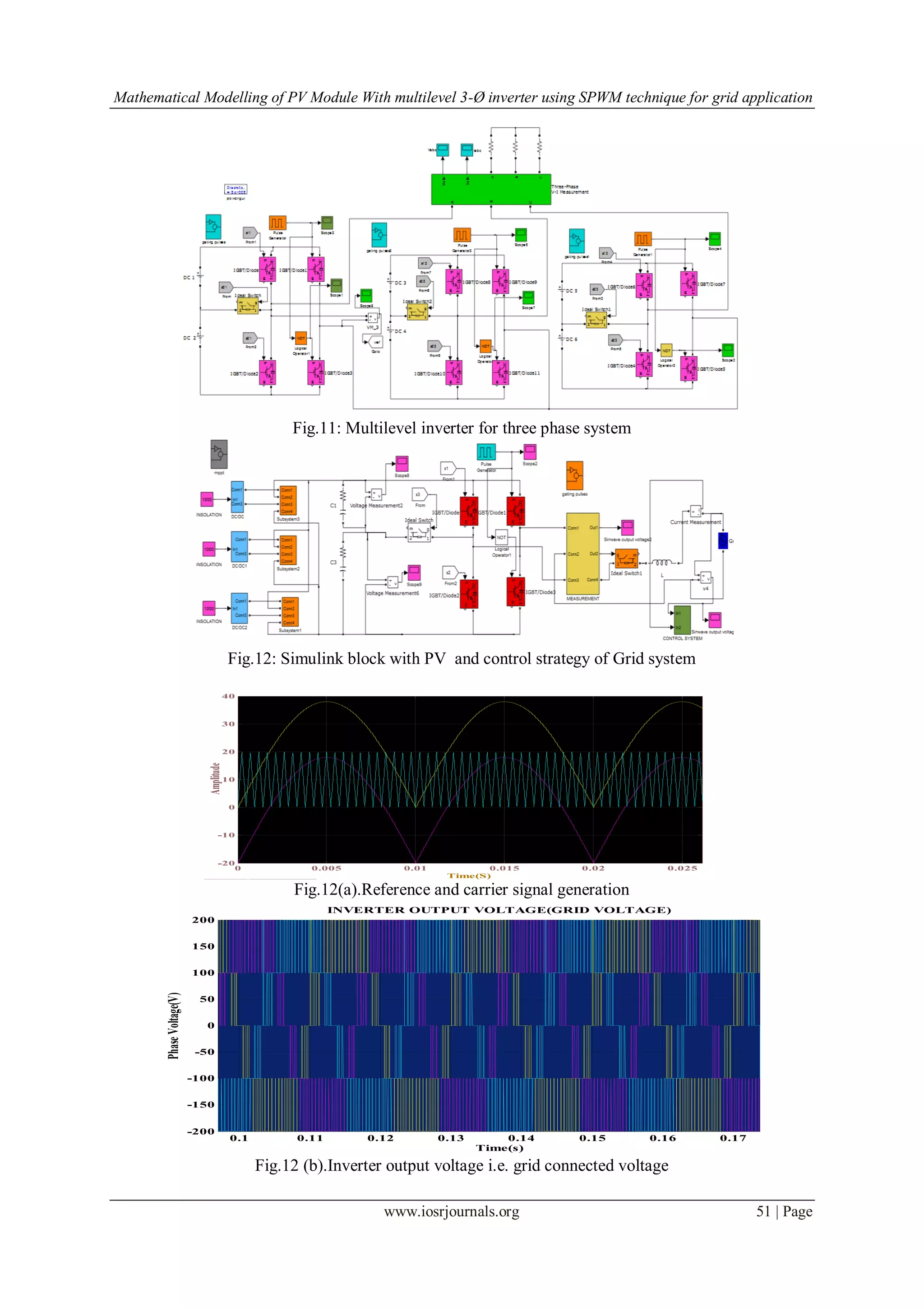
Fig.12(c).Inverter output current i.e. grid current
Fig.12(d).FFT analysis of grid connected system_R_ Phase
VII. Conclusion
This paper has presented the step-by-step procedure for modelling the PV module is presented with
three-phase multistring five-level inverter for PV application. This mathematical modelling procedure serves as
an aid to induce more people into photovoltaic research and gain a closer understanding of I-V and P-V
characteristics of PV module. A novel PWM control scheme with two reference signals and a carrier signal has
been used to generate the PWM switching signals. The circuit topology, control algorithm, and operating
principle of the proposed inverter have been analysed in detail. The configuration is suitable for PV application
as the PV strings operate independently and later expansion is possible. Furthermore, the experimental results
indicate that the THD of the multistring five-level inverter is much less than that of the conventional multistring
three-level inverter. In addition, both grid voltage and grid current are in phase at near-unity power factor.
References
Proceedings Papers:
[1 ] M.Veerachary, “Power Tracking for Nonlinear PV Sources with Coupled Inductor SEPIC Converter,” IEEE Transactions on
Aerospace and Electronic Systems, vol. 41, No. 3, July 2005.
[2] I. H. Altas and A.M. Sharaf, “A Photovoltaic Array Simulation Model for Matlab-Simulink GUI Environment,” IEEE, Clean
Electrical Power, International Conference on Clean Electrical Power (ICCEP '07), June 14-16, 2007, Ischia, Italy.
[3] S.Chowdhury, S.P.Chowdhury, G.A.Taylor, and Y.H.Song, “Mathematical Modelling and Performance Evaluation of a Stand-
Alone Polycrystalline PV Plant with MPPT Facility,” IEEE Power and Energy Society General Meeting - Conversion and Delivery
of Electrical Energy in the 21st Century, July 20-24, 2008, Pittsburg, USA.
[4] Jee-Hoon Jung, and S. Ahmed, “Model Construction of Single Crystalline Photovoltaic Panels for Real-time Simulation,” IEEE
Energy Conversion Congress & Expo, September 12-16, 2010, Atlanta, USA.
[5] S. Nema, R.K.Nema, and G.Agnihotri, “Matlab / Simulink based study of photovoltaic cells / modules / array and their
experimental verification,” International Journal of Energy and Environment, pp.487- 500, Volume 1, Issue 3, 2010.
[6] N. A. Rahim and S. Mekhilef, “Implementation of three-phase grid connected inverter for photovoltaic solar power generation
system,” in Proc. IEEE PowerCon, Oct. 2002, vol. 1, pp. 570–573.
0.02 0.03 0.04 0.05 0.06 0.07 0.08
-10
-5
0
5
10
Time(s)
Gridcurrent(A)
GRID CURRENT](https://image.slidesharecdn.com/f0844353-140508020105-phpapp01/75/Mathematical-Modelling-of-PV-Module-With-multilevel-3-O-inverter-using-SPWM-technique-for-Grid-application-10-2048.jpg)
![Mathematical Modelling of PV Module With multilevel 3-Ø inverter using SPWM technique for grid application
www.iosrjournals.org 53 | Page
Journal Papers:
[7] Aryuanto Soetedjo*, Abraham Lomi, Yusuf Ismail Nakhoda, Awan Uji Krismanto, “Modelling of Maximum Power Point Tracking
Controller for Solar Power System: TELKOMNIKA, , pp. 419~430 e-ISSN: 2087-278X.,Vol.10, No.3, July 2012.
[8] V. Fernão Pires*, J. F. Martins**, D. Foito*, Chen Hão , “ A Grid Connected Photovoltaic System with a Multilevel Inverter and a
Le-Blanc Transformer,” INTERNATIONAL JOURNAL of RENEWABLE ENERGY RESEARCH Vitor Fernão Pires et al., Vol.2,
No.1, 2012.
[9] Alias Khamis, Mohamed,H. Shareef,A. Ayob” Modelling and simulation of a micro grid tested using photovoltaic and battery
based power generation” Journal of Asian Scientific Research 2(11):658-666
[10] Tarak Salmi*, Mounir Bouzguenda**, Adel Gastli**, Ahmed Masmoudi* “MATLAB/Simulink Based Modelling of Solar
Photovoltaic Cell,” INTERNATIONAL JOURNAL of RENEWABLE ENERGY RESEARCH Tarak Salmi et al., Vol.2, No.2, 2012.
[11] M. Meinhardt and G. Cramer, “Past, present and future of grid-connected photovoltaic- and hybrid-power-systems,” in Proc. IEEE-
PES Summer Meeting, Jul. 2000, vol. 2, pp. 1283–1288.
Proceedings Papers:
[12] S. Kouro, J. Rebolledo, and J. Rodriguez, “Reduced switching-frequency modulation algorithm for high-power multilevel
inverters,” IEEE Trans. Ind. Electron., vol. 54, no. 5, pp. 2894–2901, Oct. 2007.
[13] S. J. Park, F. S. Kang, M. H. Lee, and C. U. Kim, “A new single-phase five level PWM inverter employing a deadbeat control
scheme,” IEEE Trans. Power Electron., vol. 18, no. 18, pp. 831–843, May 2003.
[14] L. M. Tolbert and T. G. Habetler, “Novel multilevel inverter carrier-based PWM method,” IEEE Trans. Ind. Appl., vol. 35, no. 5,
pp. 1098–1107, Sep./Oct. 1999.
[15] Y. Liu, H. Hong, and A. Q. Huang, “Real-time calculation of switching angles minimizing THD for multilevel inverters with step
modulation,” IEEE Trans. Ind. Electron., vol. 56, no. 2, pp. 285–293, Feb. 2009.
[16] N. S. Choi, J. G. Cho, and G. H. Cho, “A general circuit topology of multilevel inverter,” in Proc. IEEE 22th Annu. PESC, Jun. 24–
27, 1991, pp. 96–103.
[17] G. Carrara, S. Gardella, M. Marchesoni, R. Salutari, and G. Sciutto, “A new multilevel PWM method: A theoretical analysis,” IEEE
Trans. Power Electron., vol. 7, no. 3, pp. 497–505, Jul. 1992.
IX. NOMENCLATURE
Vpv is output voltage of a PV module (V)
Ipv is output current of a PV module (A)
Tr is the reference temperature = 298 K
T is the module operating temperature in Kelvin
Iph is the light generated current in a PV module (A)
Io is the PV module saturation current (A)
A = B is an ideality factor = 1.6
k is Boltz man constant = 1.3805 × 10⁻²³ J/K
q is Electron charge = 1.6 × 10⁻¹⁹ C
Rs is the series resistance of a PV module
ISCr is the PV module short-circuit current at 25 oC at 1000W/m2 = 2.55A
Ki is the short-circuit current temperature co-efficient at ISCr = 0.0017A / oC
𝜆 is the PV module illumination (W/m2) = 1000W/m2
Ego is the band gap for silicon = 1.1 eV
Ns is the number of cells connected in series
Ma is Modulation index
Vout Inverter output voltage
Vg is Grid voltage,Ig is Grid current
Np is the number of cells connected in parallel.
Lunavath. Hemsingh was born in Andhra Pradesh, India, in 1988. He received the B.Tech
(EEE) degree from Jawaharlal Nehru Technological University, Hyderabad, India, in 2010,
The M.Tech. Degree in power and Energy systems from the National Institute of Technology
Karnataka, Surathkal, India in 2012 He is currently Working as a Asst.Execuitive Engineer
(Electrical) ,Power Electronics & Automation division in Neyveli Lignite Corporation Ltd
,Tamilnadu,India. His research interests are Power electronics and Automation of multilevel
inverters, PI current control techniques, photovoltaic inverters, and dc–dc converters.](https://image.slidesharecdn.com/f0844353-140508020105-phpapp01/75/Mathematical-Modelling-of-PV-Module-With-multilevel-3-O-inverter-using-SPWM-technique-for-Grid-application-11-2048.jpg)

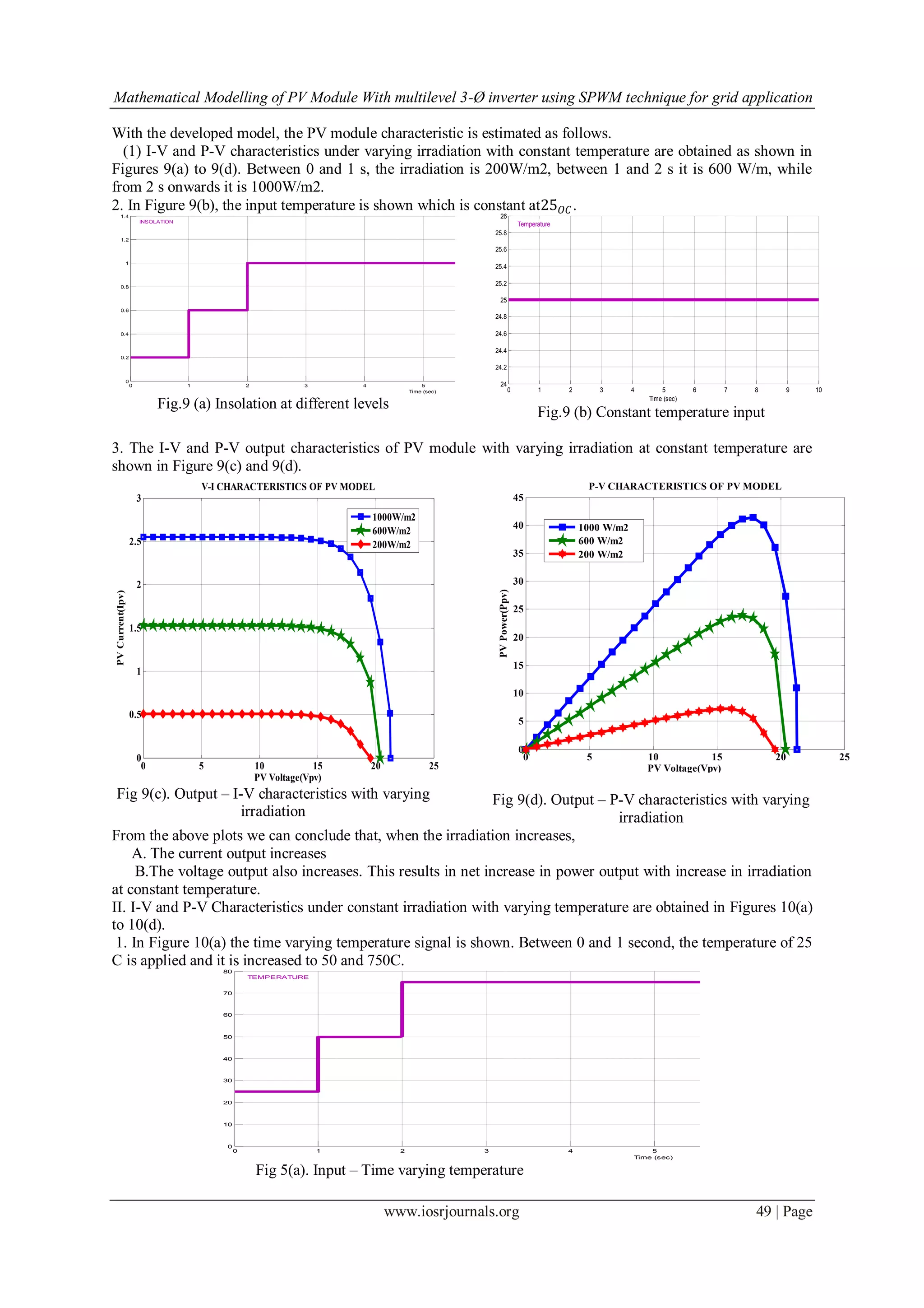
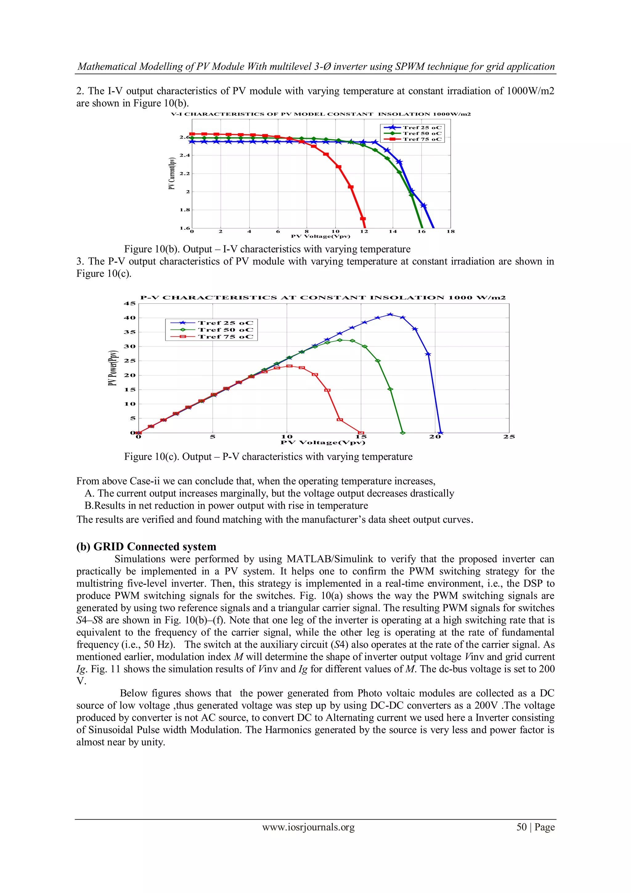
1. The document presents a mathematical model of a photovoltaic (PV) module and grid-connected system using a three-phase multistring inverter with sinusoidal pulse width modulation (SPWM) control scheme. 2. The PV module is modeled using equations that account for factors like photocurrent, saturation current, series and shunt resistances, and temperature. The model is implemented in Simulink. 3. A three-phase multistring five-level inverter topology is proposed consisting of three PV strings connected to a common DC bus through DC-DC converters. SPWM control is used to generate switching signals and produce a five-level output voltage to reduce harmonics.