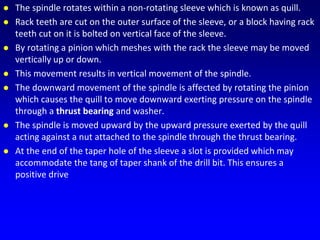
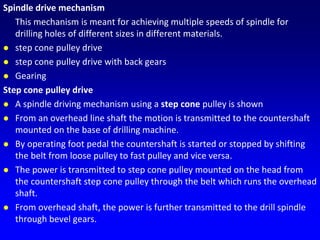
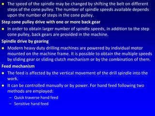
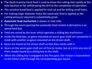
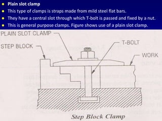
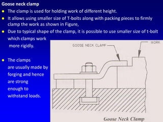
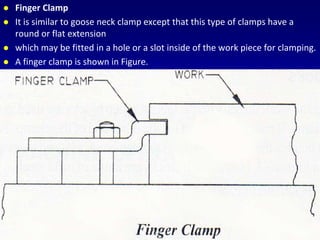
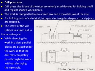
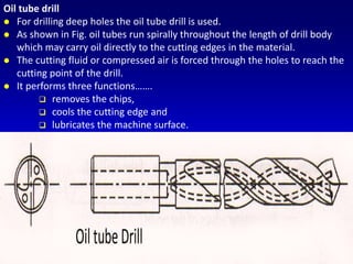
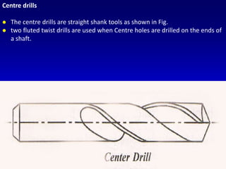
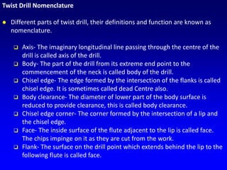
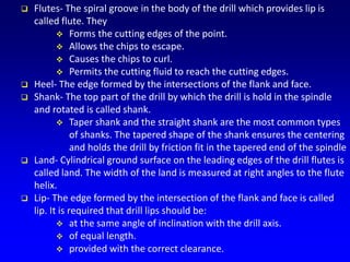
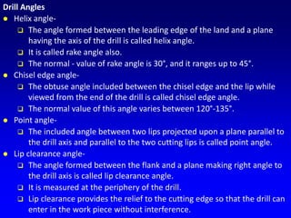
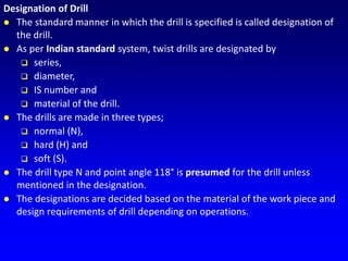
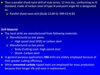
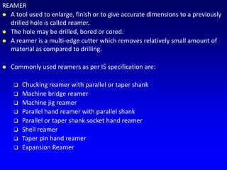
Downloaded 260 times
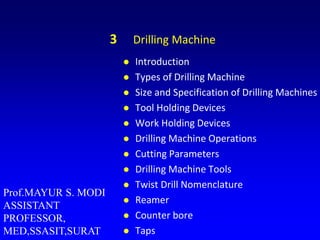
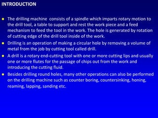
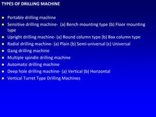

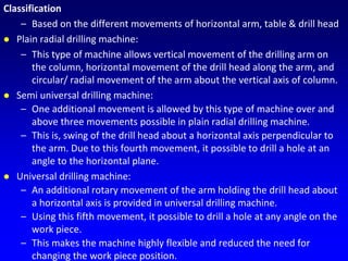
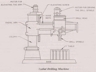


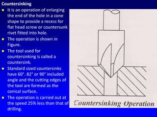
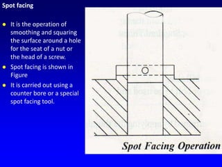

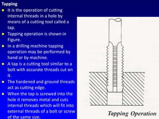
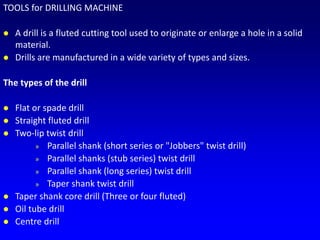


The document discusses different types of drilling machines. It describes portable, sensitive, upright, radial, gang, and deep hole drilling machines. It provides details on the typical parts of drilling machines like the base, column, table, head, spindle, and feed mechanisms. It also explains twist drills, reamers, counterbores, and taps used with drilling machines.


