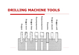
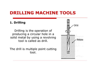
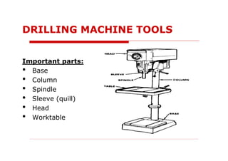
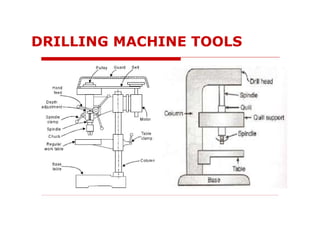
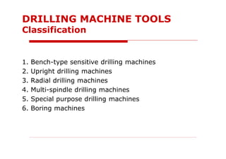
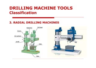
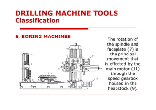
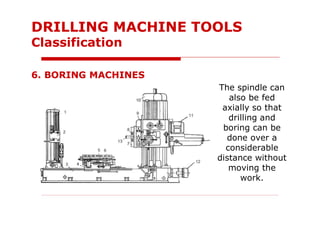
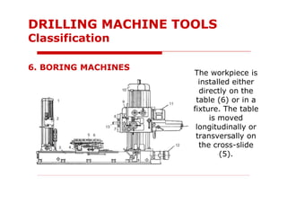
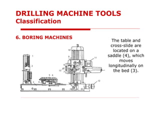
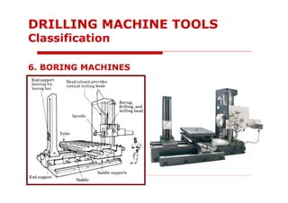
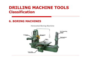
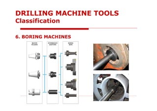
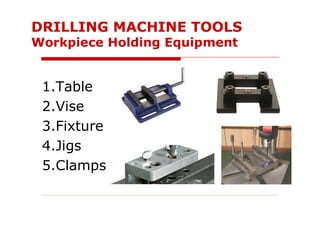
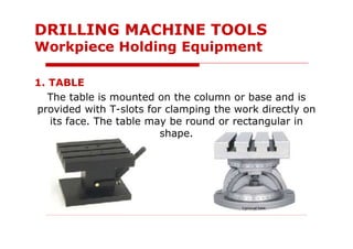
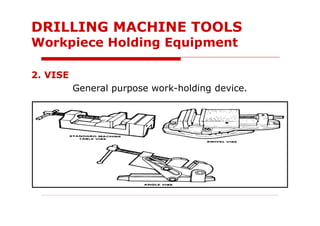
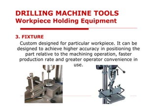
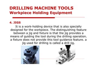
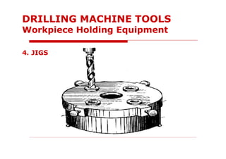
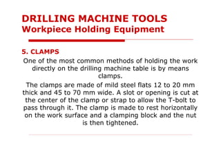
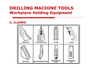
MACHINE TOOLS
1
LECTURE NOTES 5
Working principles of drilling machine tool and
its mechanism
A drilling machine tool, called a drill press, is used to
produce holes into or through workpiece material.
Drill is held in the drilling machine by a chuck or Morse
taper and is rotated and fed into the workpiece at
variable speeds.
DRILLING MACHINE TOOLS
Drilling machines can perform various machining
operations:
Drilling, boring, core drilling, step drilling, counter
sinking, boring, counter boring, spot facing, reaming
and tapping.
DRILLING MACHINE TOOLS
1. Drilling
Drilling is the operation of
producing a circular hole in a
solid metal by using a revolving
tool is called as drill.
The drill is multiple point cutting
tool.
DRILLING MACHINE TOOLS
2. Boring
Boring is a process of enlarging
a drilled hole by using an
adjustable cutting tool called as
boring tool.
The boring operation is used to
finish a drilled hole to accurate
size and to correct the
roughness of hole.
DRILLING MACHINE TOOLS
3. Counter boring
The operation which is used for enlarging only limited
portion of the hole is called as counter boring and the
tool used for this purpose is called as counter bore.
DRILLING MACHINE TOOLS
4. Reaming
Reaming is an operation of
finishing already drilled hole.
Material removal in reaming is
negligible.
The tool used for reaming
operation is called as a reamer.
DRILLING MACHINE TOOLS
5. Counter sinking
Counter sinking operation is used for enlarging the end
of the tool and give it a conical shape for a short
length. The tool is used for this operation is called a
counter sink.
DRILLING MACHINE TOOLS
6. Tapping
Tapping is the process of
making threads in a drilled hole.
The tool used for tapping is
called a Tap.
DRILLING MACHINE TOOLS
Important parts:
• Base
• Column
• Spindle
• Sleeve (quill)
• Head
• Worktable
DRILLING MACHINE TOOLS
BASE
The base supports the entire machine.
It should be bolted to the floor.
The top of the base is similar to a worktable and
maybe equipped with T-slots for mounting workpiece
too large for the table.
DRILLING MACHINE TOOLS
Important Parts
COLUMN
The column of most drill machines is circular and built
rugged and solid.
The column supports the head and the sleeve or quill
assembly.
DRILLING MACHINE TOOLS
Important Parts
SPINDLE
The spindle holds the drill (cutting tool) and revolves in
a fixed position in a sleeve.
In most drilling machines, the spindle is vertical and
work is supported on a horizontal table.
DRILLING MACHINE TOOLS
Important Parts
SLEEVE (QUILL)
The sleeve (quill) does not revolve but may slide in its
bearing in a direction parallel to its axis.
When the sleeve carrying the spindle with a cutting tool
is lowered, the cutting tool is fed into the workpiece.
When it is moved upward, the cutting tool is withdrawn
from the workpiece.
Feed pressure applied to the sleeve by hand or power
causes the revolving drill to cut its way into the
workpiece.
DRILLING MACHINE TOOLS
Important Parts
HEAD
The head of drill press is composed of the sleeve,
spindle, electric motor and feed mechanism.
The head is connected to the column.
DRILLING MACHINE TOOLS
Important Parts
WORKTABLE
The worktable is supported on an arm mounted to the
column.
The worktable can be adjusted vertically to
accommodate different heights of workpiece.
It may be swung completely out of the way.
DRILLING MACHINE TOOLS
Important Parts
Stepped type driving mechanisms are widely used.
Stepless type driving mechanisms have found limited
application according to drilling machine type
(automatic feed mechanism)
DRILLING MACHINE TOOLS
Driving Mechanism
DRILLING MACHINE TOOLS
Driving Mechanism
Belt Transmission
DRILLING MACHINE TOOLS
Driving Mechanism
DRILLING MACHINE TOOLS
Driving Mechanism
Pick-off Gear
Mechanism
1. Bench-type sensitive drilling machines
2. Upright drilling machines
3. Radial drilling machines
4. Multi-spindle drilling machines
5. Special purpose drilling machines
6. Boring machines
DRILLING MACHINE TOOLS
Classification
1. BENCH-TYPE DRILLING MACHINES
These drilling machines are used for machining small
diameter holes of 0.25–12 mm diameter. Manual
feeding characterizes this machine and that is why they
are called “sensitive”.
DRILLING MACHINE TOOLS
Classification
2. UPRIGHT DRILLING MACHINES
They are used for machining holes up to 50 mm in
diameter in relatively small-size work. It has a wide
range of spindle speed and feeds. Therefore, they are
employed not only for drilling, but also core drilling,
reaming, and tapping operations.
DRILLING MACHINE TOOLS
Classification
2. UPRIGHT DRILLING MACHINES
DRILLING MACHINE TOOLS
Classification
2. UPRIGHT DRILLING MACHINES
DRILLING MACHINE TOOLS
Classification
1- Table
2- Vertical drill spindle
3- Sleeve
4- Cone pulley
5- V-belt
6- Head
7- Driving motor
8- Vertical column
9- Base
2. UPRIGHT DRILLING MACHINES
DRILLING MACHINE TOOLS
Classification
2. UPRIGHT DRILLING MACHINES
DRILLING MACHINE TOOLS
Classification
3. RADIAL DRILLING MACHINES
They are especially designed from drilling, counter
boring, counter sinking, reaming and tapping holes in
heavy and bulky workpieces that are inconvenient or
impossible to machine on the upright drilling machines.
They are suitable for multi-tool machining in individual
and batch production.
DRILLING MACHINE TOOLS
Classification
3. RADIAL DRILLING MACHINES
DRILLING MACHINE TOOLS
Classification
3. RADIAL DRILLING MACHINES
DRILLING MACHINE TOOLS
Classification
3. RADIAL DRILLING MACHINES
Based on the type and number of movements possible
the radial drilling machine can be grouped as
a) Plain radial drilling machine
b) Semi-universal radial drilling machine
c) Universal radial drilling machine
DRILLING MACHINE TOOLS
Classification
3. RADIAL DRILLING MACHINES
a) Plain radial drilling machine
In these type of machine three principle movements
are possible
i. Vertical movement of the arm along the column
ii. Horizontal movement of the drill head along the
column
iii. Swinging movement of the arm in horizontal
plane about the vertical column
DRILLING MACHINE TOOLS
Classification
3. RADIAL DRILLING MACHINES
b) Semi-universal radial drilling machine
In these type of machine in addition above three
movements, the drill head can be swung about the
horizontal axis which is normal to the arm.
This fourth movement of the drill head enables drilling
of holes at desired inclination with the normal
vertical position.
DRILLING MACHINE TOOLS
Classification
3. RADIAL DRILLING MACHINES
c) Universal radial drilling machine
In these machine, the arm itself can be rotated
through desired angle along horizontal axis.
This is an addition to the four movement available on a
semi-universal drilling machine.
All these five movements in universal machine enable it
to drill on the workpiece at any angle.
DRILLING MACHINE TOOLS
Classification
4. MULTI-SPINDLE DRILLING MACHINES
They are mainly used in lot (mass) production for
machining workpieces requiring simultaneous drilling,
reaming and tapping of a large number of holes in
different planes of the workpiece.
A single spindle drilling machine is not economical for
such purpose, as not only a considerably large number
of machines and operators are required but also the
machining cycle is longer.
DRILLING MACHINE TOOLS
Classification
4. MULTI-SPINDLE DRILLING MACHINES
There are three types of multi-spindle drilling
machines:
a) Gang multi-spindle drilling machines
b) Adjustable-center multi-spindle vertical drilling
machines
c) Unit-type multi-spindle drilling machines
DRILLING MACHINE TOOLS
Classification
4. MULTI-SPINDLE DRILLING MACHINES
a) Gang multi-spindle drilling machines
The spindles (2-6) are arranged in a row, and each
spindle is driven by its own motor.
The gang machine is in fact several upright drilling
machines having a common base and single worktable.
They are used for consecutive machining of different
holes in one workpiece, or for the machining of a single
hole with different cutting tools.
DRILLING MACHINE TOOLS
Classification
4. MULTI-SPINDLE DRILLING MACHINES
a) Gang multi-spindle drilling machines
DRILLING MACHINE TOOLS
Classification
4. MULTI-SPINDLE DRILLING MACHINES
a) Gang multi-spindle drilling machines
DRILLING MACHINE TOOLS
Classification
4. MULTI-SPINDLE DRILLING MACHINES
a) Gang multi-spindle drilling machines
DRILLING MACHINE TOOLS
Classification
4. MULTI-SPINDLE DRILLING MACHINES
b) Adjustable-center multi-spindle vertical
drilling machines
These differ from gang-type machines in that they
have a common drive for all working spindles.
The spindles are adjusted in the spindle head for
drilling holes of varying diameters at random locations
on the workpiece surface.
DRILLING MACHINE TOOLS
Classification
4. MULTI-SPINDLE DRILLING MACHINES
b) Adjustable-center multi-spindle vertical
drilling machines
DRILLING MACHINE TOOLS
Classification
4. MULTI-SPINDLE DRILLING MACHINES
c) Unit-type multi-spindle drilling machines
These are widely used in mass production.
They are, as a rule, chiefly built of standard units.
Such machines are designed for machining a definite
component held in a jig and are frequently built into an
automatic transfer machine.
DRILLING MACHINE TOOLS
Classification
4. MULTI-SPINDLE DRILLING MACHINES
c) Unit-type multi-spindle drilling machines
DRILLING MACHINE TOOLS
Classification
5. SPECIAL PURPOSE DRILLING MACHINES
Such machines are usually equipped with powerful
pumps, which deliver cutting fluid under high pressure,
either through the hollow drilling tool or through the
clearance between the drill stem and the machined
hole.
The cutting fluid washes out the chips produced by
drilling.
DRILLING MACHINE TOOLS
Classification
5. SPECIAL PURPOSE DRILLING MACHINES
In deep hole drilling, the workpiece is rotated by
chuck and supported by a steady rest while the drill is
fed axially.
This process reduces the amount by which the drill
departs from the drilled hole center. Deep-hole drilling
machines (also called drill lathes) are intended for
drilling hole having a length-to-diameter ratio of 10 or
more.
DRILLING MACHINE TOOLS
Classification
5. SPECIAL PURPOSE DRILLING MACHINES
DRILLING MACHINE TOOLS
Classification
In these machines, the workpiece remains stationary; the
tool rotates and may simultaneously perform a feed motion.
The boring machine is designed to machine relatively large,
irregular, and bulky workpieces that cannot be easily
rotated.
Among the operations performed on this machine are
boring, facing, drilling, counterboring, counterfacing,
external and internal thread cutting, and milling.
6. BORING MACHINES
DRILLING MACHINE TOOLS
Classification
The cutting tool
is mounted
either in the
spindle (13) or
on the facing
slide (8).
6. BORING MACHINES
DRILLING MACHINE TOOLS
Classification
The rotation of
the spindle and
faceplate (7) is
the principal
movement that
is effected by the
main motor (11)
through the
speed gearbox
housed in the
headstock (9).
6. BORING MACHINES
DRILLING MACHINE TOOLS
Classification
The spindle can
also be fed
axially so that
drilling and
boring can be
done over a
considerable
distance without
moving the
work.
6. BORING MACHINES
DRILLING MACHINE TOOLS
Classification
The workpiece is
installed either
directly on the
table (6) or in a
fixture. The table
is moved
longitudinally or
transversally on
the cross-slide
(5).
6. BORING MACHINES
DRILLING MACHINE TOOLS
Classification
The table and
cross-slide are
located on a
saddle (4), which
moves
longitudinally on
the bed (3).
6. BORING MACHINES
DRILLING MACHINE TOOLS
Classification
The headstock
(9) moves
vertically along
the column (10)
simultaneously
with the spindle
rest (2), which is
moving vertically
along the end
support column
(1).
6. BORING MACHINES
DRILLING MACHINE TOOLS
Classification
The spindle
travels axially
when boring or
cutting internal
thread, and so
on. The facing
slide is moved
radially on the
faceplate to
perform facing
operations.
6. BORING MACHINES
DRILLING MACHINE TOOLS
Classification
The rotational
speed of the
faceplate is
much less than
that of the
spindle. The
table feed and its
rapid reverse are
powered by the
motor (12).
6. BORING MACHINES
DRILLING MACHINE TOOLS
Classification
In some setups,
the work is fed
toward the tool,
while in other
cases, the tool is
fed toward the
work.
6. BORING MACHINES
DRILLING MACHINE TOOLS
Classification
6. BORING MACHINES
DRILLING MACHINE TOOLS
Classification
6. BORING MACHINES
DRILLING MACHINE TOOLS
Classification
6. BORING MACHINES
DRILLING MACHINE TOOLS
Classification
6. BORING MACHINES
DRILLING MACHINE TOOLS
Classification
1.Table
2.Vise
3.Fixture
4.Jigs
5.Clamps
DRILLING MACHINE TOOLS
Workpiece Holding Equipment
1. TABLE
The table is mounted on the column or base and is
provided with T-slots for clamping the work directly on
its face. The table may be round or rectangular in
shape.
DRILLING MACHINE TOOLS
Workpiece Holding Equipment
2. VISE
General purpose work-holding device.
DRILLING MACHINE TOOLS
Workpiece Holding Equipment
3. FIXTURE
Custom designed for particular workpiece. It can be
designed to achieve higher accuracy in positioning the
part relative to the machining operation, faster
production rate and greater operator convenience in
use.
DRILLING MACHINE TOOLS
Workpiece Holding Equipment
4. JIGS
It is a work-holding device that is also specially
designed for the workpiece. The distinguishing feature
between a jig and fixture is that the jig provides a
means of guiding the tool during the drilling operation.
a fixture does not provide this tool guidance feature. a
jig used for drilling is called a drill jig.
DRILLING MACHINE TOOLS
Workpiece Holding Equipment
4. JIGS
DRILLING MACHINE TOOLS
Workpiece Holding Equipment
5. CLAMPS
One of the most common methods of holding the work
directly on the drilling machine table is by means
clamps.
The clamps are made of mild steel flats 12 to 20 mm
thick and 45 to 70 mm wide. A slot or opening is cut at
the center of the clamp or strap to allow the T-bolt to
pass through it. The clamp is made to rest horizontally
on the work surface and a clamping block and the nut
is then tightened.
DRILLING MACHINE TOOLS
Workpiece Holding Equipment
5. CLAMPS
DRILLING MACHINE TOOLS
Workpiece Holding Equipment
The different methods used for holding drill in a drill
spindle are;
• By directly fitting in the spindle hole
• By using drill sleeve
• By using drill chuck
DRILLING MACHINE TOOLS
Tool Holding Equipment
By directly fitting in the spindle hole
DRILLING MACHINE TOOLS
Tool Holding Equipment
By using drill sleeve
DRILLING MACHINE TOOLS
Tool Holding Equipment
Where a cutting tool or Chuck has
a Morse taper smaller than that of
the spindle, the difference is made
up by using a sleeve.
For example, a drill with a No. 1
Morse taper shank to be fitted in a
spindle with a No. 2 Morse taper
would require a 1-2 sleeve.
Drills and similar tools with parallel shanks are held in
a drill chuck.
By rotating the outer sleeve, the jaws can be opened
and closed.
To ensure maximum grip, the chuck should be
tightened using the correct size of chuck key. This
prevents the drill from spinning during use and
chewing up the drill shank.
DRILLING MACHINE TOOLS
Tool Holding Equipment
By using drill chuck
DRILLING MACHINE TOOLS
Tool Holding Equipment
By using drill chuck
DRILLING MACHINE TOOLS
Tool Holding Equipment
By using drill chuck

Chapter 5 Drilling gstbvggfffddggyg ppt.pdf

  • 1.
    MACHINE TOOLS 1 LECTURE NOTES5 Working principles of drilling machine tool and its mechanism
  • 2.
    A drilling machinetool, called a drill press, is used to produce holes into or through workpiece material. Drill is held in the drilling machine by a chuck or Morse taper and is rotated and fed into the workpiece at variable speeds. DRILLING MACHINE TOOLS
  • 3.
    Drilling machines canperform various machining operations: Drilling, boring, core drilling, step drilling, counter sinking, boring, counter boring, spot facing, reaming and tapping. DRILLING MACHINE TOOLS
  • 4.
  • 5.
    1. Drilling Drilling isthe operation of producing a circular hole in a solid metal by using a revolving tool is called as drill. The drill is multiple point cutting tool. DRILLING MACHINE TOOLS
  • 6.
    2. Boring Boring isa process of enlarging a drilled hole by using an adjustable cutting tool called as boring tool. The boring operation is used to finish a drilled hole to accurate size and to correct the roughness of hole. DRILLING MACHINE TOOLS
  • 7.
    3. Counter boring Theoperation which is used for enlarging only limited portion of the hole is called as counter boring and the tool used for this purpose is called as counter bore. DRILLING MACHINE TOOLS
  • 8.
    4. Reaming Reaming isan operation of finishing already drilled hole. Material removal in reaming is negligible. The tool used for reaming operation is called as a reamer. DRILLING MACHINE TOOLS
  • 9.
    5. Counter sinking Countersinking operation is used for enlarging the end of the tool and give it a conical shape for a short length. The tool is used for this operation is called a counter sink. DRILLING MACHINE TOOLS
  • 10.
    6. Tapping Tapping isthe process of making threads in a drilled hole. The tool used for tapping is called a Tap. DRILLING MACHINE TOOLS
  • 11.
    Important parts: • Base •Column • Spindle • Sleeve (quill) • Head • Worktable DRILLING MACHINE TOOLS
  • 12.
  • 13.
    BASE The base supportsthe entire machine. It should be bolted to the floor. The top of the base is similar to a worktable and maybe equipped with T-slots for mounting workpiece too large for the table. DRILLING MACHINE TOOLS Important Parts
  • 14.
    COLUMN The column ofmost drill machines is circular and built rugged and solid. The column supports the head and the sleeve or quill assembly. DRILLING MACHINE TOOLS Important Parts
  • 15.
    SPINDLE The spindle holdsthe drill (cutting tool) and revolves in a fixed position in a sleeve. In most drilling machines, the spindle is vertical and work is supported on a horizontal table. DRILLING MACHINE TOOLS Important Parts
  • 16.
    SLEEVE (QUILL) The sleeve(quill) does not revolve but may slide in its bearing in a direction parallel to its axis. When the sleeve carrying the spindle with a cutting tool is lowered, the cutting tool is fed into the workpiece. When it is moved upward, the cutting tool is withdrawn from the workpiece. Feed pressure applied to the sleeve by hand or power causes the revolving drill to cut its way into the workpiece. DRILLING MACHINE TOOLS Important Parts
  • 17.
    HEAD The head ofdrill press is composed of the sleeve, spindle, electric motor and feed mechanism. The head is connected to the column. DRILLING MACHINE TOOLS Important Parts
  • 18.
    WORKTABLE The worktable issupported on an arm mounted to the column. The worktable can be adjusted vertically to accommodate different heights of workpiece. It may be swung completely out of the way. DRILLING MACHINE TOOLS Important Parts
  • 19.
    Stepped type drivingmechanisms are widely used. Stepless type driving mechanisms have found limited application according to drilling machine type (automatic feed mechanism) DRILLING MACHINE TOOLS Driving Mechanism
  • 20.
  • 21.
    Belt Transmission DRILLING MACHINETOOLS Driving Mechanism
  • 22.
    DRILLING MACHINE TOOLS DrivingMechanism Pick-off Gear Mechanism
  • 23.
    1. Bench-type sensitivedrilling machines 2. Upright drilling machines 3. Radial drilling machines 4. Multi-spindle drilling machines 5. Special purpose drilling machines 6. Boring machines DRILLING MACHINE TOOLS Classification
  • 24.
    1. BENCH-TYPE DRILLINGMACHINES These drilling machines are used for machining small diameter holes of 0.25–12 mm diameter. Manual feeding characterizes this machine and that is why they are called “sensitive”. DRILLING MACHINE TOOLS Classification
  • 25.
    2. UPRIGHT DRILLINGMACHINES They are used for machining holes up to 50 mm in diameter in relatively small-size work. It has a wide range of spindle speed and feeds. Therefore, they are employed not only for drilling, but also core drilling, reaming, and tapping operations. DRILLING MACHINE TOOLS Classification
  • 26.
    2. UPRIGHT DRILLINGMACHINES DRILLING MACHINE TOOLS Classification
  • 27.
    2. UPRIGHT DRILLINGMACHINES DRILLING MACHINE TOOLS Classification 1- Table 2- Vertical drill spindle 3- Sleeve 4- Cone pulley 5- V-belt 6- Head 7- Driving motor 8- Vertical column 9- Base
  • 28.
    2. UPRIGHT DRILLINGMACHINES DRILLING MACHINE TOOLS Classification
  • 29.
    2. UPRIGHT DRILLINGMACHINES DRILLING MACHINE TOOLS Classification
  • 30.
    3. RADIAL DRILLINGMACHINES They are especially designed from drilling, counter boring, counter sinking, reaming and tapping holes in heavy and bulky workpieces that are inconvenient or impossible to machine on the upright drilling machines. They are suitable for multi-tool machining in individual and batch production. DRILLING MACHINE TOOLS Classification
  • 31.
    3. RADIAL DRILLINGMACHINES DRILLING MACHINE TOOLS Classification
  • 32.
    3. RADIAL DRILLINGMACHINES DRILLING MACHINE TOOLS Classification
  • 33.
    3. RADIAL DRILLINGMACHINES Based on the type and number of movements possible the radial drilling machine can be grouped as a) Plain radial drilling machine b) Semi-universal radial drilling machine c) Universal radial drilling machine DRILLING MACHINE TOOLS Classification
  • 34.
    3. RADIAL DRILLINGMACHINES a) Plain radial drilling machine In these type of machine three principle movements are possible i. Vertical movement of the arm along the column ii. Horizontal movement of the drill head along the column iii. Swinging movement of the arm in horizontal plane about the vertical column DRILLING MACHINE TOOLS Classification
  • 35.
    3. RADIAL DRILLINGMACHINES b) Semi-universal radial drilling machine In these type of machine in addition above three movements, the drill head can be swung about the horizontal axis which is normal to the arm. This fourth movement of the drill head enables drilling of holes at desired inclination with the normal vertical position. DRILLING MACHINE TOOLS Classification
  • 36.
    3. RADIAL DRILLINGMACHINES c) Universal radial drilling machine In these machine, the arm itself can be rotated through desired angle along horizontal axis. This is an addition to the four movement available on a semi-universal drilling machine. All these five movements in universal machine enable it to drill on the workpiece at any angle. DRILLING MACHINE TOOLS Classification
  • 37.
    4. MULTI-SPINDLE DRILLINGMACHINES They are mainly used in lot (mass) production for machining workpieces requiring simultaneous drilling, reaming and tapping of a large number of holes in different planes of the workpiece. A single spindle drilling machine is not economical for such purpose, as not only a considerably large number of machines and operators are required but also the machining cycle is longer. DRILLING MACHINE TOOLS Classification
  • 38.
    4. MULTI-SPINDLE DRILLINGMACHINES There are three types of multi-spindle drilling machines: a) Gang multi-spindle drilling machines b) Adjustable-center multi-spindle vertical drilling machines c) Unit-type multi-spindle drilling machines DRILLING MACHINE TOOLS Classification
  • 39.
    4. MULTI-SPINDLE DRILLINGMACHINES a) Gang multi-spindle drilling machines The spindles (2-6) are arranged in a row, and each spindle is driven by its own motor. The gang machine is in fact several upright drilling machines having a common base and single worktable. They are used for consecutive machining of different holes in one workpiece, or for the machining of a single hole with different cutting tools. DRILLING MACHINE TOOLS Classification
  • 40.
    4. MULTI-SPINDLE DRILLINGMACHINES a) Gang multi-spindle drilling machines DRILLING MACHINE TOOLS Classification
  • 41.
    4. MULTI-SPINDLE DRILLINGMACHINES a) Gang multi-spindle drilling machines DRILLING MACHINE TOOLS Classification
  • 42.
    4. MULTI-SPINDLE DRILLINGMACHINES a) Gang multi-spindle drilling machines DRILLING MACHINE TOOLS Classification
  • 43.
    4. MULTI-SPINDLE DRILLINGMACHINES b) Adjustable-center multi-spindle vertical drilling machines These differ from gang-type machines in that they have a common drive for all working spindles. The spindles are adjusted in the spindle head for drilling holes of varying diameters at random locations on the workpiece surface. DRILLING MACHINE TOOLS Classification
  • 44.
    4. MULTI-SPINDLE DRILLINGMACHINES b) Adjustable-center multi-spindle vertical drilling machines DRILLING MACHINE TOOLS Classification
  • 45.
    4. MULTI-SPINDLE DRILLINGMACHINES c) Unit-type multi-spindle drilling machines These are widely used in mass production. They are, as a rule, chiefly built of standard units. Such machines are designed for machining a definite component held in a jig and are frequently built into an automatic transfer machine. DRILLING MACHINE TOOLS Classification
  • 46.
    4. MULTI-SPINDLE DRILLINGMACHINES c) Unit-type multi-spindle drilling machines DRILLING MACHINE TOOLS Classification
  • 47.
    5. SPECIAL PURPOSEDRILLING MACHINES Such machines are usually equipped with powerful pumps, which deliver cutting fluid under high pressure, either through the hollow drilling tool or through the clearance between the drill stem and the machined hole. The cutting fluid washes out the chips produced by drilling. DRILLING MACHINE TOOLS Classification
  • 48.
    5. SPECIAL PURPOSEDRILLING MACHINES In deep hole drilling, the workpiece is rotated by chuck and supported by a steady rest while the drill is fed axially. This process reduces the amount by which the drill departs from the drilled hole center. Deep-hole drilling machines (also called drill lathes) are intended for drilling hole having a length-to-diameter ratio of 10 or more. DRILLING MACHINE TOOLS Classification
  • 49.
    5. SPECIAL PURPOSEDRILLING MACHINES DRILLING MACHINE TOOLS Classification
  • 50.
    In these machines,the workpiece remains stationary; the tool rotates and may simultaneously perform a feed motion. The boring machine is designed to machine relatively large, irregular, and bulky workpieces that cannot be easily rotated. Among the operations performed on this machine are boring, facing, drilling, counterboring, counterfacing, external and internal thread cutting, and milling. 6. BORING MACHINES DRILLING MACHINE TOOLS Classification
  • 51.
    The cutting tool ismounted either in the spindle (13) or on the facing slide (8). 6. BORING MACHINES DRILLING MACHINE TOOLS Classification
  • 52.
    The rotation of thespindle and faceplate (7) is the principal movement that is effected by the main motor (11) through the speed gearbox housed in the headstock (9). 6. BORING MACHINES DRILLING MACHINE TOOLS Classification
  • 53.
    The spindle can alsobe fed axially so that drilling and boring can be done over a considerable distance without moving the work. 6. BORING MACHINES DRILLING MACHINE TOOLS Classification
  • 54.
    The workpiece is installedeither directly on the table (6) or in a fixture. The table is moved longitudinally or transversally on the cross-slide (5). 6. BORING MACHINES DRILLING MACHINE TOOLS Classification
  • 55.
    The table and cross-slideare located on a saddle (4), which moves longitudinally on the bed (3). 6. BORING MACHINES DRILLING MACHINE TOOLS Classification
  • 56.
    The headstock (9) moves verticallyalong the column (10) simultaneously with the spindle rest (2), which is moving vertically along the end support column (1). 6. BORING MACHINES DRILLING MACHINE TOOLS Classification
  • 57.
    The spindle travels axially whenboring or cutting internal thread, and so on. The facing slide is moved radially on the faceplate to perform facing operations. 6. BORING MACHINES DRILLING MACHINE TOOLS Classification
  • 58.
    The rotational speed ofthe faceplate is much less than that of the spindle. The table feed and its rapid reverse are powered by the motor (12). 6. BORING MACHINES DRILLING MACHINE TOOLS Classification
  • 59.
    In some setups, thework is fed toward the tool, while in other cases, the tool is fed toward the work. 6. BORING MACHINES DRILLING MACHINE TOOLS Classification
  • 60.
    6. BORING MACHINES DRILLINGMACHINE TOOLS Classification
  • 61.
    6. BORING MACHINES DRILLINGMACHINE TOOLS Classification
  • 62.
    6. BORING MACHINES DRILLINGMACHINE TOOLS Classification
  • 63.
    6. BORING MACHINES DRILLINGMACHINE TOOLS Classification
  • 64.
  • 65.
    1. TABLE The tableis mounted on the column or base and is provided with T-slots for clamping the work directly on its face. The table may be round or rectangular in shape. DRILLING MACHINE TOOLS Workpiece Holding Equipment
  • 66.
    2. VISE General purposework-holding device. DRILLING MACHINE TOOLS Workpiece Holding Equipment
  • 67.
    3. FIXTURE Custom designedfor particular workpiece. It can be designed to achieve higher accuracy in positioning the part relative to the machining operation, faster production rate and greater operator convenience in use. DRILLING MACHINE TOOLS Workpiece Holding Equipment
  • 68.
    4. JIGS It isa work-holding device that is also specially designed for the workpiece. The distinguishing feature between a jig and fixture is that the jig provides a means of guiding the tool during the drilling operation. a fixture does not provide this tool guidance feature. a jig used for drilling is called a drill jig. DRILLING MACHINE TOOLS Workpiece Holding Equipment
  • 69.
    4. JIGS DRILLING MACHINETOOLS Workpiece Holding Equipment
  • 70.
    5. CLAMPS One ofthe most common methods of holding the work directly on the drilling machine table is by means clamps. The clamps are made of mild steel flats 12 to 20 mm thick and 45 to 70 mm wide. A slot or opening is cut at the center of the clamp or strap to allow the T-bolt to pass through it. The clamp is made to rest horizontally on the work surface and a clamping block and the nut is then tightened. DRILLING MACHINE TOOLS Workpiece Holding Equipment
  • 71.
    5. CLAMPS DRILLING MACHINETOOLS Workpiece Holding Equipment
  • 72.
    The different methodsused for holding drill in a drill spindle are; • By directly fitting in the spindle hole • By using drill sleeve • By using drill chuck DRILLING MACHINE TOOLS Tool Holding Equipment
  • 73.
    By directly fittingin the spindle hole DRILLING MACHINE TOOLS Tool Holding Equipment
  • 74.
    By using drillsleeve DRILLING MACHINE TOOLS Tool Holding Equipment Where a cutting tool or Chuck has a Morse taper smaller than that of the spindle, the difference is made up by using a sleeve. For example, a drill with a No. 1 Morse taper shank to be fitted in a spindle with a No. 2 Morse taper would require a 1-2 sleeve.
  • 75.
    Drills and similartools with parallel shanks are held in a drill chuck. By rotating the outer sleeve, the jaws can be opened and closed. To ensure maximum grip, the chuck should be tightened using the correct size of chuck key. This prevents the drill from spinning during use and chewing up the drill shank. DRILLING MACHINE TOOLS Tool Holding Equipment By using drill chuck
  • 76.
    DRILLING MACHINE TOOLS ToolHolding Equipment By using drill chuck
  • 77.
    DRILLING MACHINE TOOLS ToolHolding Equipment By using drill chuck