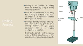
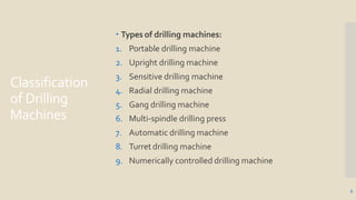
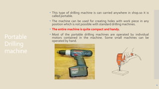
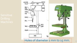
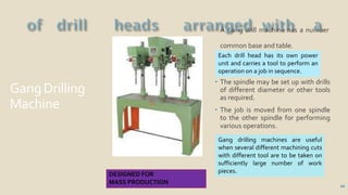
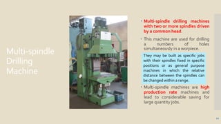
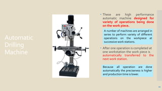
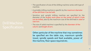
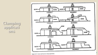
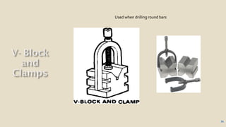
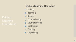
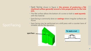
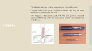
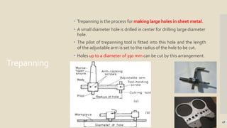
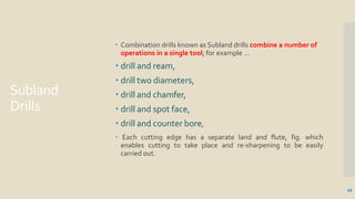
Drilling
Process
• Drilling is the process of cutting
holes in metals by using a drilling
machine as shown
• Drills are the tools used to cut away
fine shavings of material as thedrill
2
advances in a rotational motion
through the material.
• Drilling is done by forcinga rotating
stationary drill
drilling machine or
in
drill into stationary job as on a
by
a
forcing
rotating
workpeiece as on a lathe.
• Drilling also done by milling machine
with a drilling attachment. In this
case the job is fed onto rotating drill.
Classification
of Drilling
Machines
3
 Types of drilling machines:
1. Portable drilling machine
2. Upright drilling machine
3. Sensitive drilling machine
4. Radial drilling machine
5. Gang drilling machine
6. Multi-spindle drilling press
7. Automatic drilling machine
8. Turret drilling machine
9. Numerically controlled drilling machine
Portable
Drilling
machine
 This type of drilling machine is can carried anywhere in shop.so it is
called portable.
 The machine can be used for creating holes with work piece in any
position which is not possible with standard drilling machines.
 The entire machine is quite compact and handy.
 Most of the portable drilling machines are operated by individual
motors contained in the machine. Some small machines can be
operated by hand.
4
Sensitive
Drilling
Machines
5Holes of diameter 1 mm to 15 mm.
Workingof
Sensitive
Drilling
Machine
6
 These are small machines designed for drilling holes at high speed in
light work pieces.
 As shown in figure the machine consists of a vertical column, a
horizontal table, a machine head mounted on the column to support
the driving motor, and mechanism for driving and feeding the tool.
 While feeding the operator can sense the cutting action and adjust
the feed rate so it is called sensitive drilling machine.
 the machine can be fitted on a table or the floor.
•Work piece with the exact location marked on it with the center punch is
clamped rigidly on the work table.
• spindle axis and center punch indentation are in same line.
•Machine is started and drill bit is lowered by rotating feed handle.
•Drill bit touches the work and starts removing material.
Upright
Drilling
Machine
 The column may be round or of
box section.
 It can be raised or lowered along
the pillar depending upon the
height of the job clamped in
position for rigidly.
 The table in the case can be
rotated about its own axis and
clamped in position.
 The swivel of the table about the
pillar and rotation of the table
about its center permits easy
location of the job under the drill.
Similar in design to sensitive type but
it is larger &more sturdily built.
7
8
Radial
Drilling
Machine
9
 The arm can be moved up and down the column and swiveled
about the column and drill head also can be moved along the radial
arm.
 The motion of head along with the drill spindle permits
positioning of holes in a circle with a radius almost as large as
the length of radial arm so this is called radial drill machine.
 The rotating spindle can be moved up and down relative to the arm
through the feed mechanism.
 Radial drilling machines are convenient for heavy jobs which
cannot be moved around easily and for drilling a numbers of holes
in a job.
 Power feeding is also available in radial drilling machine.
Holes up to 7.5 cm.
GangDrilling
Machine
 A Gang drill machine has a number
common base and table.
 The spindle may be set up with drills
of different diameter or other tools
as required.
 The job is moved from one spindle
to the other spindle for performing
various operations.
10
Each drill head has its own power
unit and carries a tool to perform an
operation on a job in sequence.
Gang drilling machines are useful
when several different machining cuts
with different tool are to be taken on
sufficiently large number of work
pieces.
DESIGNED FOR
MASS PRODUCTION
Multi-spindle
Drilling
Machine
 Multi-spindle drilling machines
with two or more spindles driven
by a common head.
 This machine are used for drilling
a numbers of holes
simultaneously in a worpiece.
 Multi-spindle machines are high
production rate machines and
lead to considerable saving for
large quantity jobs.
They may be built as specific jobs
with their spindles fixed in specific
positions or as general purpose
machines in which the relative
distance between the spindles can
be changed within a range.
11
Automatic
Drilling
Machine
 These are high performance
automatic machine designed for
variety of operations being done
on the work piece.
 After one operation is completed at
one workstation the work piece is
automatically transferred to the
next work station.
A number of machines are arranged in
series to perform variety of different
operations on the workpiece at
successive work stations.
12
Because all operation are done
automatically the preciseness is higher
and production time is lower.
Drill Machine
Specifications
13
 The specification of size of the drilling machine varies with type of
machine.
 A portable drilling machine is specific by the maximum diameter
of the drill that it can be hold.
 Sensitive and upright drilling machine are specified by the
diameter of the largest work piece on the center of which a hole
can be drilled; also by the maximum size of the drill held in steel or
cast iron.
 The size of radial machine is specified by the diameter of the
column and length of arm.
Other particular of the machine that may sometimes
be specified are the table size, maximum spindle
travel, spindle speeds and feed available, power of
the machine, floor space required etc.
14
DrillBits
15
 A drill bit is a multi-point tool and typically has a pointed end. A
twist drill is the most common type used.
 Twist drills are available with parallel shanks up to 16mm diameter
and with taper shanks up to 100mm diameter
 Standard lengths are known as jobber-series twist drills, short
drills are known as stub series, and long drills as long series and
extra long series.
 Different helix angles are available for drilling a range of
materials.
Manufactured from three main
materials
1. Carbon-tool steels
2. High-speed steel
3. Cemented-carbide
16
Types
Drill Bit Types
- Installer Bit
- Twist Bit
- Brad Point Bit
- Auger Bit
- Self-Feed Bit
- Spade Bit
- Hole Saw
- Glass /TileBit
- Forstner Bit
- Plug Cutter
Drill Bit
Types
Twist Bit Brad Point Bit Auger Bit PlugCutter Glass / Tile
Bit
17
Installer Bit
18
Installing phone wire,
TV cable, computer
and security system
wire.
Has a hole for pulling
wire through the
material you're
drilling.
Self-Feed Bit
19
pHas a screw at the ti
that draws the bit
through the work
piece.
SpadeBit
Boring large diameter holes
Available from 1/4 inch to 1-1/2
inches in diameter.
Has a point that centers and
steadies the bit.
The cutting edges may have
points that help create a neater
entry hole.
20
HoleSaw
Boring in wood and light metal.
21
A pilot bit centers and steadies
the cutting blade.
22
.
Creates flat-bottomed holes.
Flutes
•Flutes
23
are
incorporated to carry
away the chips of
metal and the outside
surface is relieved to
a cutting
along the
side of each
produce
edge
leading
flute.
Drill Bit
Features
 The point of the drill is ground to an angle of 118 degrees
 each side is ground back to give " relief " of about 12 degrees to
each cutting edge as shown
24
ToolHolding
 Drills and similar tools with parallel shanks are held in a drill chuck.
 By rotating the outer sleeve, the jaws can be opened and closed.
 To ensure maximum grip, the chuck should be tightened using the
correct size of chuck key. This prevents the drill from spinning
during use and chewing up the drill shank.
25
ToolHolding
 The chuck is fitted with a Morse-taper shank which fits into a
corresponding Morse taper in the spindle.
 Drills are also available with Morse-taper shanks which fit directly
into the spindle without the need for a chuck.
Holding taper shank drills
26
ToolHolding
 Where a cutting tool or chuck has a Morse taper smaller than that
of the spindle, the difference is made up by using a sleeve.
Morse taper sleeve
27
28
Work
Holding
Devices
29
 When drilling a hole on a drilling it is important that the
workpiece be secured rigidly to the machine table or
base.
 Not properly secured work piece may be dangerous
except in the case of small drills and very large work
pieces.
 The workpiece can be secured in many ways depending
upon the size of the job and the accuracy desired.
 A workpiece may be stopped from turning by fixing an
obstruction on its way or it may be clamped to the
machine table by using bolts or straps.
Drilling
MachineVice
 The Machine Vice has slots in the side of the base of the vice
which enable the user to screw the Machine Vice to the Drilling
Machine table.
30
31
Direct
Clamping
Clamping set
32
34
Used when drilling round bars
34
HandVice
35
36
Drilling
Machine
Operations
37
Drilling Machine Operation :
1. Drilling
2. Reaming
3. Boring
4. Counter boring
5. Counter sinking
6. Spot facing
7. Tapping
8. Trepanning
Drilling
 Drilling is the operation of producing circular holes in solid metal
by rotating the drill and feeding it through the job. This is the main
operation done on the this machine.
 Before starting the drilling it is necessary to mark the position of the
hole on the work piece.
 Drilling process is dose not produce accurate hole. The center may
not be accurate, the size of the hole is slightly larger than required.
38
40
Reaming
40
 Reaming is an operation of sizing and shaping a hole using a tool
called reamer.
 A reamer as shown on figure is multitoothed tool designed for
remove relatively small amount of material from a previously drilled
hole.
 Reaming is done to achieve accurate hole dimension.
 Initially a hole is drilled slightly smaller in size.
Boring
 Boring is a process of aligning, sizing and finishing a cylindricalhole.
 It uses single point cutting tool which rotates relative to the
stationary work piece.
 The hole can be aligned and sized with good surface finish.
 Boring is often used to enlarge the drilled holes.
41
43
Counterboring
43
 Counter boring is the operation of enlarging one end of an existing
hole concentric with the original hole with a square bottom as shown in
figure.
 The counter tool known as counter bore has a pilot as shown in figure.
 The pilot enters in previously drilled hole and align the tool so that the
counter bored hole is concentric with the existing hole.
 The tool has end cutting edges square with the axis to produce a flat
bottom.
 Counter boring is used to recess a bolt head or a nut below the surface to
permit a mitting part to operate with obstruction.
Counter
Sinking
 A countersink tool enlarges the top portion of an existinghole
to a cone-shaped opening.
 Countersinking is performed after drilling to provide space for the
head of a fastener, such as a screw, to sit flush with the workpiece
surface.
 Common included angles for a countersink include 60, 82, 90, 100,
118, and 120 degrees.
44
45
SpotFacing
 Spot facing shown in figure is the process of producing a flat
machined surface generally around a hole perpendicular to the hole
axis.
 This flat surface allows the bottom of a screw or bolt to seat squarely
with the material.
 Spot facing is commonly done on castings where irregular surfaces are
found.
 Spot facing may be performed on a drill press with a counter bore of
suitable size for the operation.
spot face
To seat a nut
46
Tapping
 Tapping is a thread cutting for producing internal threads.
 Tapping uses multi- point cutting tool called taps may be done
manually or on machine like drills.
 The tapping attachment used with the drill permits forward
rotation of the tap when it is cutting and fast reverse rotation for
withdrawal.
47
Trepanning
 Trepanning is the process for making large holes in sheet metal.
 A small diameter hole is drilled in center for drilling large diameter
hole.
 The pilot of trepanning tool is fitted into this hole and the length
of the adjustable arm is set to the radius of the hole to be cut.
 Holes up to a diameter of 350 mm can be cut by this arrangement.
48
Subland
Drills
49
 Combination drills known as Subland drills combine a number of
operations in a single tool; for example …
 drill and ream,
 drill two diameters,
 drill and chamfer,
 drill and spot face,
 drill and counter bore,
 Each cutting edge has a separate land and flute, fig. which
enables cutting to take place and re-sharpening to be easily
carried out.
50
• Drill axis is the longitudinal centreline.
• Drill point is the sharpened end of the drill body consisting of all that part
which is shaped to produce lips, faces and chisel edge.
• Lip or cutting edge is the edge formed by the intersectionof the flank
and face
• Lip length is the minimum distance between the outercorner and the
chisel-edge corner of the lip.
• Face is that portion of the flute surface adjacent to the lip on which the
chip impinges as it is cut from the work.
• Chisel edge is the edge formed by the intersection of the flanks.
• Flank is that surface on a drill point which extends behind the lip to the
followingflute.
• Flutes are the grooves in the body of the drill, which provide lips, allow
the removal of chips, and permit cutting fluid to reach the lips.
• Flute length is the axial length from the extreme end of the point to the
termination of the flutes at the shank end ofthe body.
• Body is that portion of the drill nomenclature, whichextends from the
extreme cutting end to the beginning of theshank.
• Shank is that portion of the drill by which it is held anddriven,
• Heel is the edge formed by the intersection of the flute surface and
the body clearance.
• Body clearance is that portion of the body surface reducedin diameter to
provide diametricclearance.
• Core or web is the central portion of the drill situated between the roots
of the flutes and extending from thepoint end towards the shank; the
point end of the core forms the chisel edge.
• Lands are the cylindrically ground surfaces on the leading edges of the
drill flutes. The width of the land is measuredat right angles to the flute.
• Recess is the portion of the drill body between the flutes and the shank
provided so as to facilitate the grinding of the body. Parallel shank drills of
small diameter are not usuallyprovided with a recess.
• Outer corner is the corner formed by the intersection of the lip and the
leading edge of the land.
• Chisel edge comer is the corner formed by the intersection of a lip and the
chisel edge.
• Drill diameter is the measurement across the cylindricallands at the outer
corners of the drill.
• Lead of helix is the distance measured parallel to the drill axis between
corresponding points on the leading edge of a flute in one complete turn
of the flute.
• Helix angle is the angle between the leading edge of the land and the drill
axis.
• Rake angle is the angle between the face and a line parallelto the drill axis.
It is bigger at the face edges and decreases towards the center of the drill
to nearly 0°. The result is that the formation of chips grows more un-
favorable towards the centre.
• Lip clearance angle is the angle formed by the flank and a plane at right
angles to the drill axis; the angle is normally measured at the periphery of
the drill. Tomake sure that the main cutting edges can enter into the
material, the clearance faces slope backwards in a curve. The clearance
angle is measured at the face edge, must amount to 5° up to8°
 Cutting speed:
The cutting speed in a drilling operation refers to the peripheral speed of a point on
the surface of the drill in contact with the work. The cutting speed (v) may be
calculated as :
v=(π*d*n)/1000 m per minute.
Where,
d is the diameter of the drill in mm
n is the rpm of the drill spindle.
 Feed:
The feed of a drill is the distance the drills moves into the work at each revolution of
the spindle. It is expressed in mm. the feed may also be expressed as feed per
minute. The feed per minute may be defined as the axial distance moved by the drill
into the work per minute. The feed per minute may be calculated as:
Sm = sr × n
Where,
Sm = feed per minute in mm. Sr =
feed per revolution in mm.
n = rpm of the drill.
 Depth of cut:
The depth of cut in drilling is equal to one half of the drill diameter. The depth of cut (t)
may be expressed as :
t =D/2 mm
 Machining timing in drilling:
T=L/(n* Sr ) min.
Where,
n = r.p.m of the drill
Sr = feed per revolution of the drill in mm. L =
length of the travel of the drill in mm.
T = machining time in min.
L = l1 + l2 + l3 +l4
Where,
l1 = length of the work piece l2 =
approach of the drill,
l3 = length of the drill point (0.29d), l4 =
over travel
59
Different ways for adding coolant fluid
60
Different types of coolants
61
62
SAFETY
PRECAUTIONS
• Do not support the workplaces by hand. Use a holding
device to prevent the workpiece from being tom from
the operator’s hand.
63
• Never make any adjustments while the machine is
• operating.
• Never clean away chips with your hand. Use a brush.
• Keep all loose clothing away from turning tools.
• Make sure that the cutting tools are running straight
• before starting the operation

Drilling Machine Presentation

  • 2.
    Drilling Process • Drilling isthe process of cutting holes in metals by using a drilling machine as shown • Drills are the tools used to cut away fine shavings of material as thedrill 2 advances in a rotational motion through the material. • Drilling is done by forcinga rotating stationary drill drilling machine or in drill into stationary job as on a by a forcing rotating workpeiece as on a lathe. • Drilling also done by milling machine with a drilling attachment. In this case the job is fed onto rotating drill.
  • 3.
    Classification of Drilling Machines 3  Typesof drilling machines: 1. Portable drilling machine 2. Upright drilling machine 3. Sensitive drilling machine 4. Radial drilling machine 5. Gang drilling machine 6. Multi-spindle drilling press 7. Automatic drilling machine 8. Turret drilling machine 9. Numerically controlled drilling machine
  • 4.
    Portable Drilling machine  This typeof drilling machine is can carried anywhere in shop.so it is called portable.  The machine can be used for creating holes with work piece in any position which is not possible with standard drilling machines.  The entire machine is quite compact and handy.  Most of the portable drilling machines are operated by individual motors contained in the machine. Some small machines can be operated by hand. 4
  • 5.
  • 6.
    Workingof Sensitive Drilling Machine 6  These aresmall machines designed for drilling holes at high speed in light work pieces.  As shown in figure the machine consists of a vertical column, a horizontal table, a machine head mounted on the column to support the driving motor, and mechanism for driving and feeding the tool.  While feeding the operator can sense the cutting action and adjust the feed rate so it is called sensitive drilling machine.  the machine can be fitted on a table or the floor. •Work piece with the exact location marked on it with the center punch is clamped rigidly on the work table. • spindle axis and center punch indentation are in same line. •Machine is started and drill bit is lowered by rotating feed handle. •Drill bit touches the work and starts removing material.
  • 7.
    Upright Drilling Machine  The columnmay be round or of box section.  It can be raised or lowered along the pillar depending upon the height of the job clamped in position for rigidly.  The table in the case can be rotated about its own axis and clamped in position.  The swivel of the table about the pillar and rotation of the table about its center permits easy location of the job under the drill. Similar in design to sensitive type but it is larger &more sturdily built. 7
  • 8.
  • 9.
    Radial Drilling Machine 9  The armcan be moved up and down the column and swiveled about the column and drill head also can be moved along the radial arm.  The motion of head along with the drill spindle permits positioning of holes in a circle with a radius almost as large as the length of radial arm so this is called radial drill machine.  The rotating spindle can be moved up and down relative to the arm through the feed mechanism.  Radial drilling machines are convenient for heavy jobs which cannot be moved around easily and for drilling a numbers of holes in a job.  Power feeding is also available in radial drilling machine. Holes up to 7.5 cm.
  • 10.
    GangDrilling Machine  A Gangdrill machine has a number common base and table.  The spindle may be set up with drills of different diameter or other tools as required.  The job is moved from one spindle to the other spindle for performing various operations. 10 Each drill head has its own power unit and carries a tool to perform an operation on a job in sequence. Gang drilling machines are useful when several different machining cuts with different tool are to be taken on sufficiently large number of work pieces. DESIGNED FOR MASS PRODUCTION
  • 11.
    Multi-spindle Drilling Machine  Multi-spindle drillingmachines with two or more spindles driven by a common head.  This machine are used for drilling a numbers of holes simultaneously in a worpiece.  Multi-spindle machines are high production rate machines and lead to considerable saving for large quantity jobs. They may be built as specific jobs with their spindles fixed in specific positions or as general purpose machines in which the relative distance between the spindles can be changed within a range. 11
  • 12.
    Automatic Drilling Machine  These arehigh performance automatic machine designed for variety of operations being done on the work piece.  After one operation is completed at one workstation the work piece is automatically transferred to the next work station. A number of machines are arranged in series to perform variety of different operations on the workpiece at successive work stations. 12 Because all operation are done automatically the preciseness is higher and production time is lower.
  • 13.
    Drill Machine Specifications 13  Thespecification of size of the drilling machine varies with type of machine.  A portable drilling machine is specific by the maximum diameter of the drill that it can be hold.  Sensitive and upright drilling machine are specified by the diameter of the largest work piece on the center of which a hole can be drilled; also by the maximum size of the drill held in steel or cast iron.  The size of radial machine is specified by the diameter of the column and length of arm. Other particular of the machine that may sometimes be specified are the table size, maximum spindle travel, spindle speeds and feed available, power of the machine, floor space required etc.
  • 14.
  • 15.
    DrillBits 15  A drillbit is a multi-point tool and typically has a pointed end. A twist drill is the most common type used.  Twist drills are available with parallel shanks up to 16mm diameter and with taper shanks up to 100mm diameter  Standard lengths are known as jobber-series twist drills, short drills are known as stub series, and long drills as long series and extra long series.  Different helix angles are available for drilling a range of materials. Manufactured from three main materials 1. Carbon-tool steels 2. High-speed steel 3. Cemented-carbide
  • 16.
    16 Types Drill Bit Types -Installer Bit - Twist Bit - Brad Point Bit - Auger Bit - Self-Feed Bit - Spade Bit - Hole Saw - Glass /TileBit - Forstner Bit - Plug Cutter
  • 17.
    Drill Bit Types Twist BitBrad Point Bit Auger Bit PlugCutter Glass / Tile Bit 17
  • 18.
    Installer Bit 18 Installing phonewire, TV cable, computer and security system wire. Has a hole for pulling wire through the material you're drilling.
  • 19.
    Self-Feed Bit 19 pHas ascrew at the ti that draws the bit through the work piece.
  • 20.
    SpadeBit Boring large diameterholes Available from 1/4 inch to 1-1/2 inches in diameter. Has a point that centers and steadies the bit. The cutting edges may have points that help create a neater entry hole. 20
  • 21.
    HoleSaw Boring in woodand light metal. 21 A pilot bit centers and steadies the cutting blade.
  • 22.
  • 23.
    Flutes •Flutes 23 are incorporated to carry awaythe chips of metal and the outside surface is relieved to a cutting along the side of each produce edge leading flute.
  • 24.
    Drill Bit Features  Thepoint of the drill is ground to an angle of 118 degrees  each side is ground back to give " relief " of about 12 degrees to each cutting edge as shown 24
  • 25.
    ToolHolding  Drills andsimilar tools with parallel shanks are held in a drill chuck.  By rotating the outer sleeve, the jaws can be opened and closed.  To ensure maximum grip, the chuck should be tightened using the correct size of chuck key. This prevents the drill from spinning during use and chewing up the drill shank. 25
  • 26.
    ToolHolding  The chuckis fitted with a Morse-taper shank which fits into a corresponding Morse taper in the spindle.  Drills are also available with Morse-taper shanks which fit directly into the spindle without the need for a chuck. Holding taper shank drills 26
  • 27.
    ToolHolding  Where acutting tool or chuck has a Morse taper smaller than that of the spindle, the difference is made up by using a sleeve. Morse taper sleeve 27
  • 28.
  • 29.
    Work Holding Devices 29  When drillinga hole on a drilling it is important that the workpiece be secured rigidly to the machine table or base.  Not properly secured work piece may be dangerous except in the case of small drills and very large work pieces.  The workpiece can be secured in many ways depending upon the size of the job and the accuracy desired.  A workpiece may be stopped from turning by fixing an obstruction on its way or it may be clamped to the machine table by using bolts or straps.
  • 30.
    Drilling MachineVice  The MachineVice has slots in the side of the base of the vice which enable the user to screw the Machine Vice to the Drilling Machine table. 30
  • 31.
  • 32.
  • 33.
  • 34.
    Used when drillinground bars 34
  • 35.
  • 36.
  • 37.
    Drilling Machine Operations 37 Drilling Machine Operation: 1. Drilling 2. Reaming 3. Boring 4. Counter boring 5. Counter sinking 6. Spot facing 7. Tapping 8. Trepanning
  • 38.
    Drilling  Drilling isthe operation of producing circular holes in solid metal by rotating the drill and feeding it through the job. This is the main operation done on the this machine.  Before starting the drilling it is necessary to mark the position of the hole on the work piece.  Drilling process is dose not produce accurate hole. The center may not be accurate, the size of the hole is slightly larger than required. 38
  • 39.
  • 40.
    Reaming 40  Reaming isan operation of sizing and shaping a hole using a tool called reamer.  A reamer as shown on figure is multitoothed tool designed for remove relatively small amount of material from a previously drilled hole.  Reaming is done to achieve accurate hole dimension.  Initially a hole is drilled slightly smaller in size.
  • 41.
    Boring  Boring isa process of aligning, sizing and finishing a cylindricalhole.  It uses single point cutting tool which rotates relative to the stationary work piece.  The hole can be aligned and sized with good surface finish.  Boring is often used to enlarge the drilled holes. 41
  • 42.
  • 43.
    Counterboring 43  Counter boringis the operation of enlarging one end of an existing hole concentric with the original hole with a square bottom as shown in figure.  The counter tool known as counter bore has a pilot as shown in figure.  The pilot enters in previously drilled hole and align the tool so that the counter bored hole is concentric with the existing hole.  The tool has end cutting edges square with the axis to produce a flat bottom.  Counter boring is used to recess a bolt head or a nut below the surface to permit a mitting part to operate with obstruction.
  • 44.
    Counter Sinking  A countersinktool enlarges the top portion of an existinghole to a cone-shaped opening.  Countersinking is performed after drilling to provide space for the head of a fastener, such as a screw, to sit flush with the workpiece surface.  Common included angles for a countersink include 60, 82, 90, 100, 118, and 120 degrees. 44
  • 45.
  • 46.
    SpotFacing  Spot facingshown in figure is the process of producing a flat machined surface generally around a hole perpendicular to the hole axis.  This flat surface allows the bottom of a screw or bolt to seat squarely with the material.  Spot facing is commonly done on castings where irregular surfaces are found.  Spot facing may be performed on a drill press with a counter bore of suitable size for the operation. spot face To seat a nut 46
  • 47.
    Tapping  Tapping isa thread cutting for producing internal threads.  Tapping uses multi- point cutting tool called taps may be done manually or on machine like drills.  The tapping attachment used with the drill permits forward rotation of the tap when it is cutting and fast reverse rotation for withdrawal. 47
  • 48.
    Trepanning  Trepanning isthe process for making large holes in sheet metal.  A small diameter hole is drilled in center for drilling large diameter hole.  The pilot of trepanning tool is fitted into this hole and the length of the adjustable arm is set to the radius of the hole to be cut.  Holes up to a diameter of 350 mm can be cut by this arrangement. 48
  • 49.
    Subland Drills 49  Combination drillsknown as Subland drills combine a number of operations in a single tool; for example …  drill and ream,  drill two diameters,  drill and chamfer,  drill and spot face,  drill and counter bore,  Each cutting edge has a separate land and flute, fig. which enables cutting to take place and re-sharpening to be easily carried out.
  • 50.
  • 52.
    • Drill axisis the longitudinal centreline. • Drill point is the sharpened end of the drill body consisting of all that part which is shaped to produce lips, faces and chisel edge. • Lip or cutting edge is the edge formed by the intersectionof the flank and face • Lip length is the minimum distance between the outercorner and the chisel-edge corner of the lip. • Face is that portion of the flute surface adjacent to the lip on which the chip impinges as it is cut from the work. • Chisel edge is the edge formed by the intersection of the flanks.
  • 53.
    • Flank isthat surface on a drill point which extends behind the lip to the followingflute. • Flutes are the grooves in the body of the drill, which provide lips, allow the removal of chips, and permit cutting fluid to reach the lips. • Flute length is the axial length from the extreme end of the point to the termination of the flutes at the shank end ofthe body. • Body is that portion of the drill nomenclature, whichextends from the extreme cutting end to the beginning of theshank. • Shank is that portion of the drill by which it is held anddriven,
  • 54.
    • Heel isthe edge formed by the intersection of the flute surface and the body clearance. • Body clearance is that portion of the body surface reducedin diameter to provide diametricclearance. • Core or web is the central portion of the drill situated between the roots of the flutes and extending from thepoint end towards the shank; the point end of the core forms the chisel edge. • Lands are the cylindrically ground surfaces on the leading edges of the drill flutes. The width of the land is measuredat right angles to the flute.
  • 55.
    • Recess isthe portion of the drill body between the flutes and the shank provided so as to facilitate the grinding of the body. Parallel shank drills of small diameter are not usuallyprovided with a recess. • Outer corner is the corner formed by the intersection of the lip and the leading edge of the land. • Chisel edge comer is the corner formed by the intersection of a lip and the chisel edge. • Drill diameter is the measurement across the cylindricallands at the outer corners of the drill. • Lead of helix is the distance measured parallel to the drill axis between corresponding points on the leading edge of a flute in one complete turn of the flute.
  • 56.
    • Helix angleis the angle between the leading edge of the land and the drill axis. • Rake angle is the angle between the face and a line parallelto the drill axis. It is bigger at the face edges and decreases towards the center of the drill to nearly 0°. The result is that the formation of chips grows more un- favorable towards the centre. • Lip clearance angle is the angle formed by the flank and a plane at right angles to the drill axis; the angle is normally measured at the periphery of the drill. Tomake sure that the main cutting edges can enter into the material, the clearance faces slope backwards in a curve. The clearance angle is measured at the face edge, must amount to 5° up to8°
  • 57.
     Cutting speed: Thecutting speed in a drilling operation refers to the peripheral speed of a point on the surface of the drill in contact with the work. The cutting speed (v) may be calculated as : v=(π*d*n)/1000 m per minute. Where, d is the diameter of the drill in mm n is the rpm of the drill spindle.  Feed: The feed of a drill is the distance the drills moves into the work at each revolution of the spindle. It is expressed in mm. the feed may also be expressed as feed per minute. The feed per minute may be defined as the axial distance moved by the drill into the work per minute. The feed per minute may be calculated as: Sm = sr × n Where, Sm = feed per minute in mm. Sr = feed per revolution in mm. n = rpm of the drill.
  • 58.
     Depth ofcut: The depth of cut in drilling is equal to one half of the drill diameter. The depth of cut (t) may be expressed as : t =D/2 mm  Machining timing in drilling: T=L/(n* Sr ) min. Where, n = r.p.m of the drill Sr = feed per revolution of the drill in mm. L = length of the travel of the drill in mm. T = machining time in min. L = l1 + l2 + l3 +l4 Where, l1 = length of the work piece l2 = approach of the drill, l3 = length of the drill point (0.29d), l4 = over travel
  • 59.
  • 60.
    Different ways foradding coolant fluid 60
  • 61.
    Different types ofcoolants 61
  • 62.
  • 63.
    SAFETY PRECAUTIONS • Do notsupport the workplaces by hand. Use a holding device to prevent the workpiece from being tom from the operator’s hand. 63 • Never make any adjustments while the machine is • operating. • Never clean away chips with your hand. Use a brush. • Keep all loose clothing away from turning tools. • Make sure that the cutting tools are running straight • before starting the operation