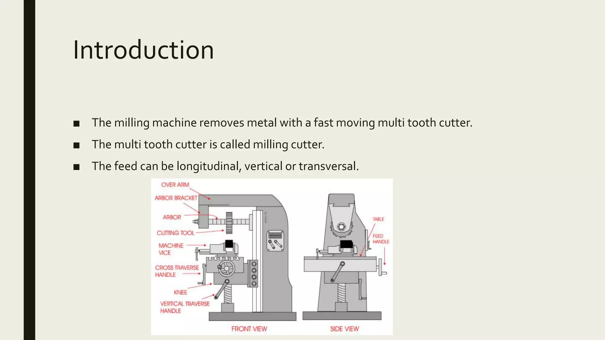
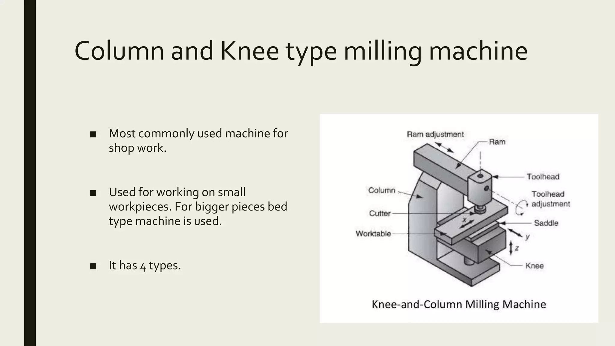
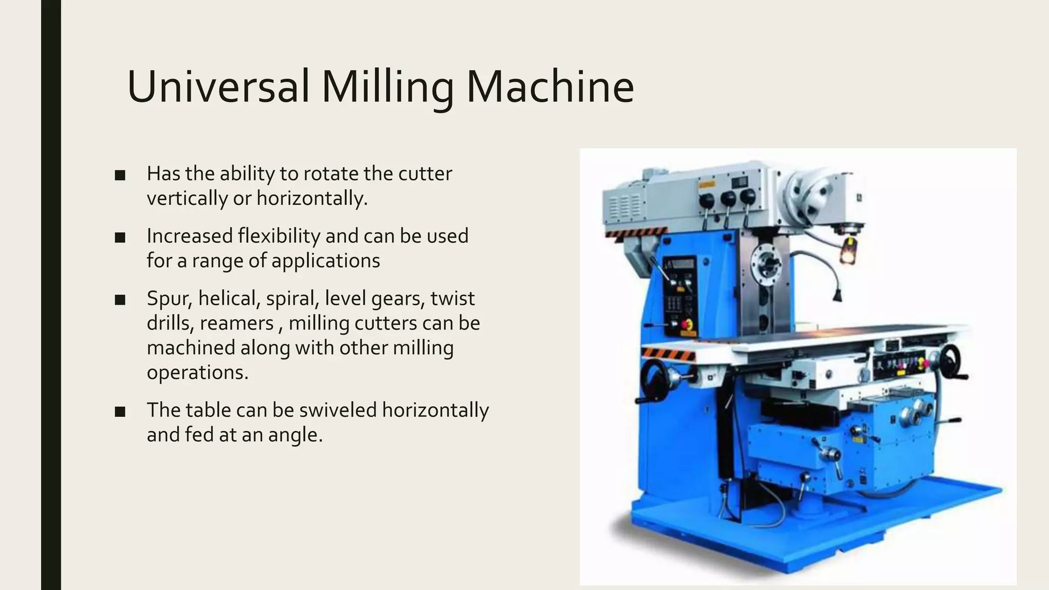
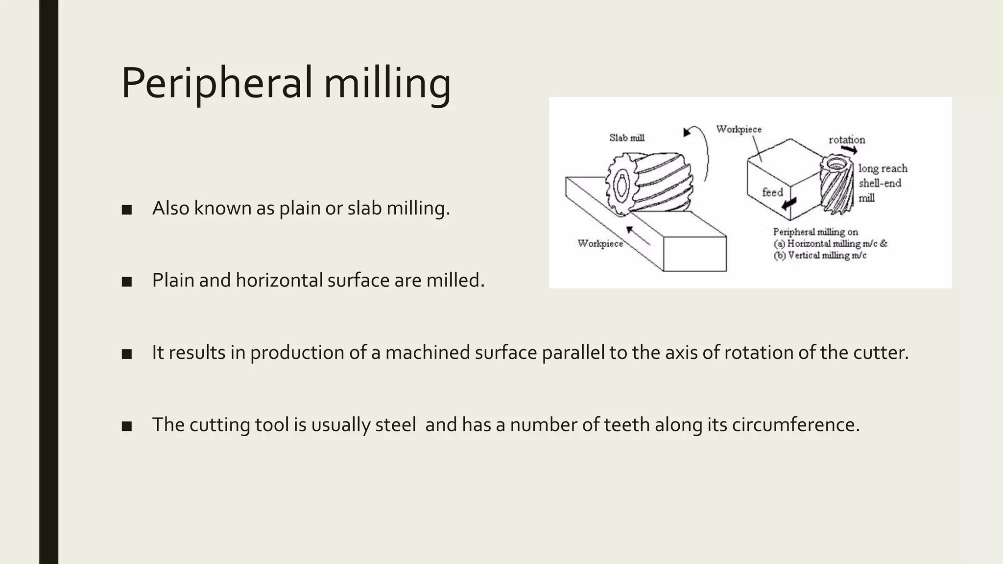
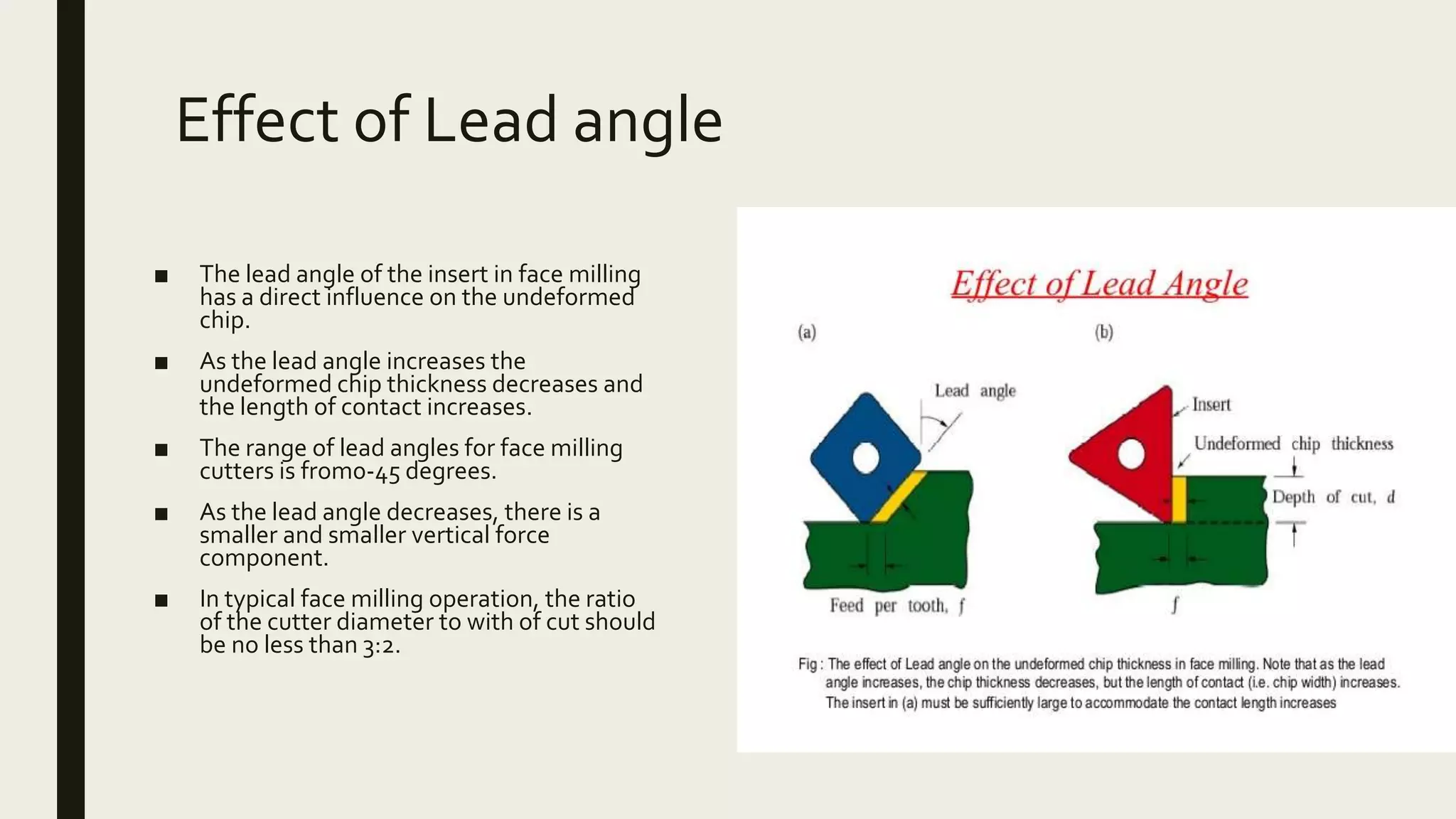
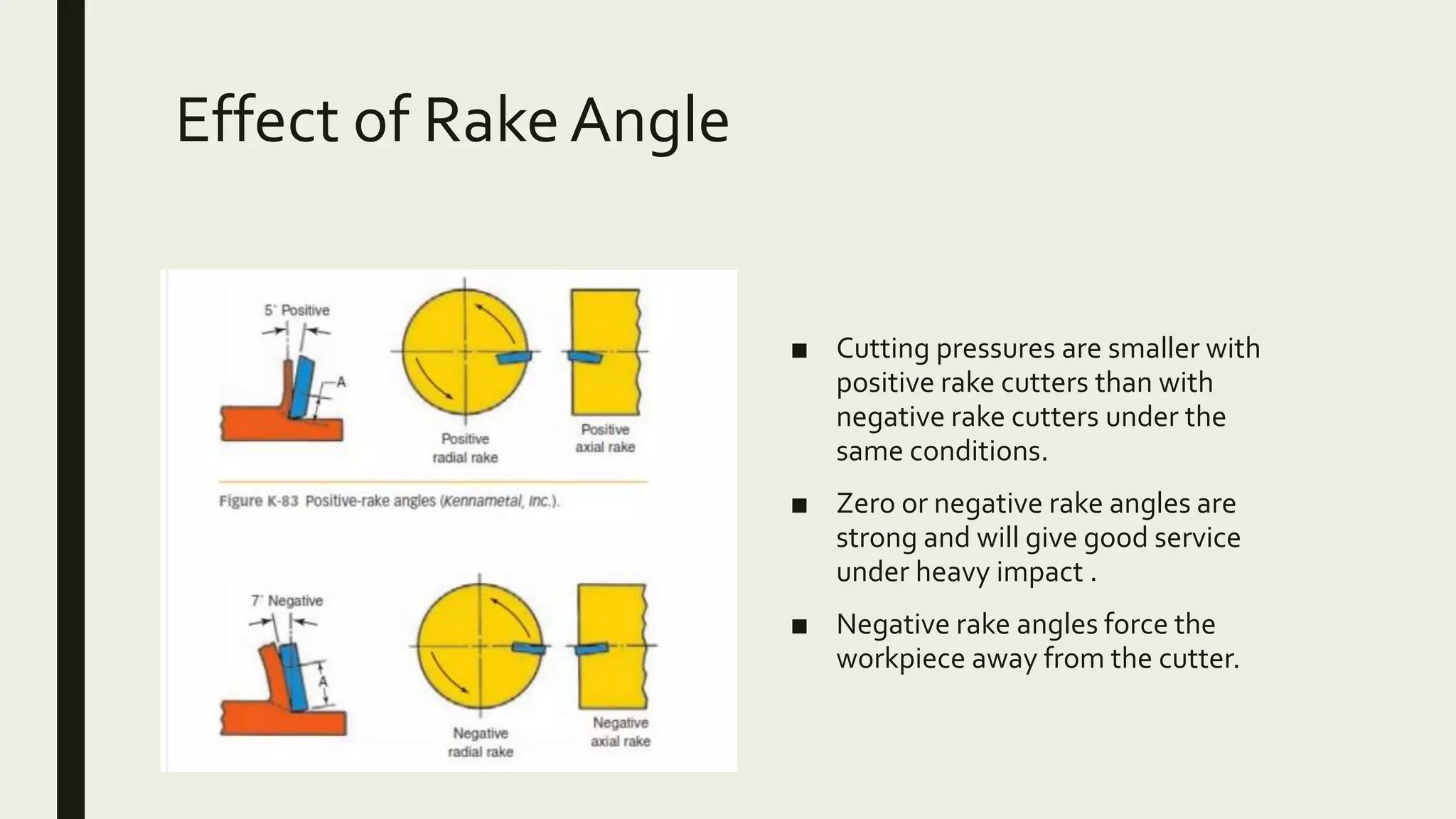
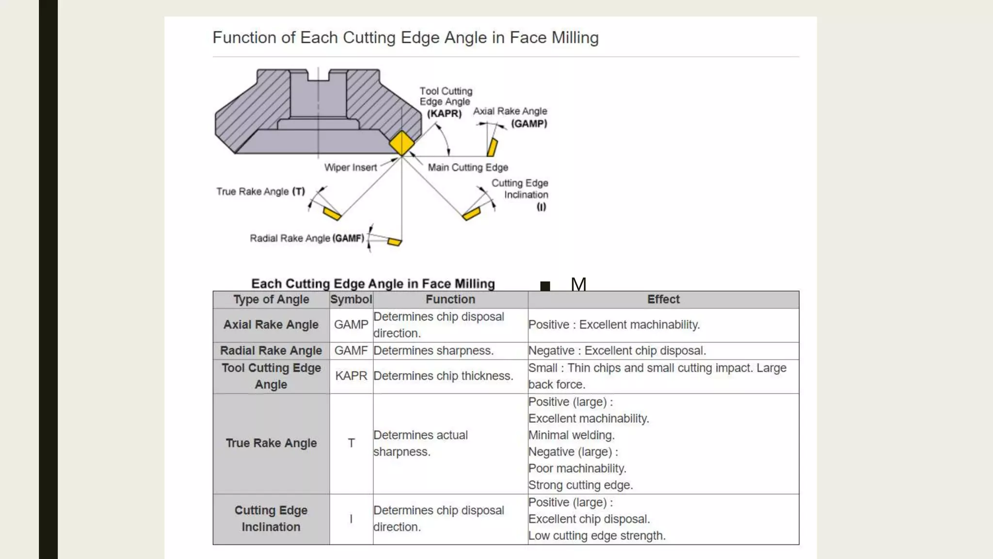
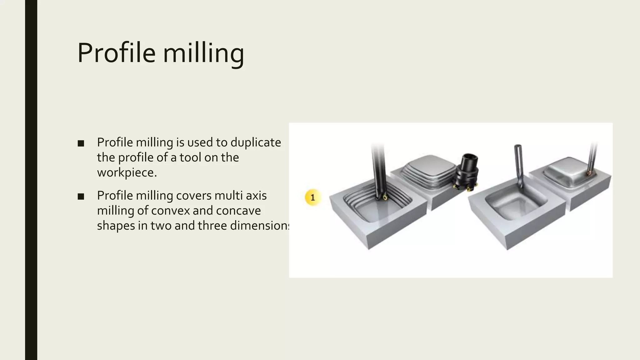
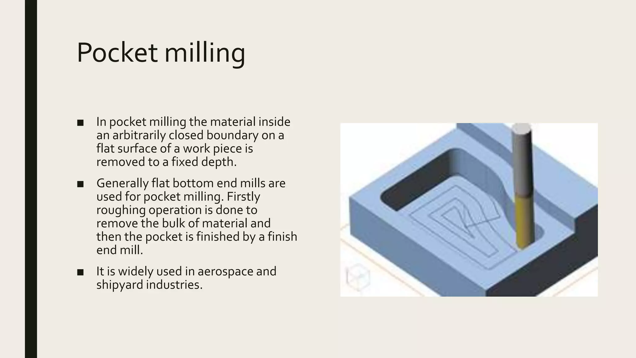
KNEE AND COLUMN MILLING
MACHINES.
TYPES OF PERIPHERAL MILLING
AND FACE MILLING
Gokulanand.P (16M213)
Mechanical Engineer,
PSG College ofTechnology
Introduction
■ The milling machine removes metal with a fast moving multi tooth cutter.
■ The multi tooth cutter is called milling cutter.
■ The feed can be longitudinal, vertical or transversal.
Types of milling machines
Column
and knee
type
Hand miller
Plain milling
Machine
Universal
milling
machine
Vertical
milling
machine
Planer milling
machine
Fixed Bed
type
Simplex Duplex Triplex
Special type CNC milling
Column and Knee type milling machine
■ Most commonly used machine for
shop work.
■ Used for working on small
workpieces. For bigger pieces bed
type machine is used.
■ It has 4 types.
Column
■ Column is a main supporting frame
for the knee,worktable,over arm
etc..and houses all the driving
mechanisms for spindle and table
feed. Column has guideways on
which knee can be moved up or
down.
Knee
■ The knee gives supports the saddle
and gives the table vertical
movement so that the depth of cut
can be adjusted.
Hand miller
■ It is the simplest and a small
machine having only hand feed for
table and power rotation of the
spindle.
■ It is used for making small jobs like
making slots, keyways and grooves.
■ It has a horizontal arbor for holding
the tool and the table usually has 3
movements.
Plain milling Machine
■ Similar to hand miller but sturdier in
construction.
■ Table has power feed in horizontal and
vertical directions.
■ It is intended for heavier milling
operations.
■ It also has a horizontal arbor and cutting
tool having hole is mounted on this arbor.
Universal Milling Machine
■ Has the ability to rotate the cutter
vertically or horizontally.
■ Increased flexibility and can be used
for a range of applications
■ Spur, helical, spiral, level gears, twist
drills, reamers , milling cutters can be
machined along with other milling
operations.
■ The table can be swiveled horizontally
and fed at an angle.
Vertical milling machine
■ Spindle is in vertical direction.
■ Small axial spindle travel permits step
milling.
■ End mill cutters and face mill cutters
are the ones commonly used.
■ They are used to produce
grooves,slots and flat surfaces.
■ Auxillary operations like drilling and
boring are also performed.
Milling
processes
End
milling
Peripheral
milling
Up milling
Down
milling
Face
milling
Peripheral milling
■ Also known as plain or slab milling.
■ Plain and horizontal surface are milled.
■ It results in production of a machined surface parallel to the axis of rotation of the cutter.
■ The cutting tool is usually steel and has a number of teeth along its circumference.
Factors in peripheral milling
■ In this process, the cutting force is not uniform throughout the length of the cut by each tooth
■ The quality of the surface generated and the shape of the chip formed depend on the rotation of
the cutter relative to the direction of feed movement of the work.
■ Due to these factors, peripheral milling results in vibrations during machining.
Cutting tool in peripheral milling
■ Cutters have straight or helical teeth.
■ Helical teeth results in oblique cutting action.
■ Straight teeth results in orthogonal cutting action.
■ Helical teeth are preferred because load on teeth is lower resulting in smooth operations
and reducing tool forces and chatter.
Up Milling
■ This is the process of metal removing by a milling cutter which is rotated against the direction of
feeding of work of the cutter.
■ The chip thickness is minimum at the beginning of the cut and reaches maximum at the end.
■ Because of this, the cutting force in up milling increases from zero to the maximum value per
tooth movement of the cutter.
■ As the cutting progresses and there is difficulty in pouring coolant on the cutting rdge of the
cutter to flush out chips, there is accumulation of chips at the cutting zone and when the chips are
carried with the cutter they spoil the work surface.
■ Since the cutter teeth do not begin cutting as a soon as they touch the work suface, in the first
instance, sliding of cutter teeth takes place for small distance on the workpiece which results in
waviness of the resulting machined surface.
Conventional or Up milling
■ The maximum chip thickness is at
the end of the cut.
■ The advantages are that tooth
engagement is not a function of
workpiece surface characteristics.
■ Contamination or scale does not
affect the tool life.
■ There is tendency for the tool to
chatter.
■ The workpiece has a tendency to
climb upwards necessitating proper
clamping.
Down milling
■ It is the process of removing metal by a
milling cutter which is rotated in the
same direction as the travel of the
workpiece.
■ The thickness of the chip is maximum
when the cutter tooth begins its cut
and minimum when the cut
terminates.
■ The cutter tooth starts removing the
material as soon as it touches the
surface and without sliding.
■ The cutting force is maximum when
the tooth begins the cut.
■ Since the cutting force is directed downwards it tends to seat the work surface firmly
on the fixture which suits more for thinner jobs being easily and firmly clamped in the
fixtures.
■ Coolant is more easily provide in this process thereby avoiding overheating and
accumulation of chips in the cutting area.
■ Better surface finish is obtained in down milling as the cutter takes a chip of zero
thickness at the end of the cut.
■ There is tendency of the cutter to pull the work forwards.
Backlash in down milling
■ It cannot be conducted in old machines having backlash error between table and feed
screw and the nut.
■ The backlash causes the work to be pulled below the cutter when the cut begins and
leaves the work free when terminated.
■ As this action is repeated during maching, vibrations in the machine are set up
damaging the work piece considerably.
■ It is because of this that down milling is performed only on those machines that are
rigid and have backlash elimination arrangement.
Face milling
■ In face milling, the cutter is mounted
on a spindle having an axis of
rotation perpendicular to the
workpiece surface.
■ The cutter rotates at a speed N and
the workpiece moves along a
straight path at linear speed v.
Effect of Lead angle
■ The lead angle of the insert in face milling
has a direct influence on the undeformed
chip.
■ As the lead angle increases the
undeformed chip thickness decreases and
the length of contact increases.
■ The range of lead angles for face milling
cutters is from0-45 degrees.
■ As the lead angle decreases, there is a
smaller and smaller vertical force
component.
■ In typical face milling operation, the ratio
of the cutter diameter to with of cut should
be no less than 3:2.
Effect of RakeAngle
■ Cutting pressures are smaller with
positive rake cutters than with
negative rake cutters under the
same conditions.
■ Zero or negative rake angles are
strong and will give good service
under heavy impact .
■ Negative rake angles force the
workpiece away from the cutter.
■ M
Profile milling
■ Profile milling is used to duplicate
the profile of a tool on the
workpiece.
■ Profile milling covers multi axis
milling of convex and concave
shapes in two and three dimensions.
Pocket milling
■ In pocket milling the material inside
an arbitrarily closed boundary on a
flat surface of a work piece is
removed to a fixed depth.
■ Generally flat bottom end mills are
used for pocket milling. Firstly
roughing operation is done to
remove the bulk of material and
then the pocket is finished by a finish
end mill.
■ It is widely used in aerospace and
shipyard industries.
Operating Guidelines for milling
■ Chamfers should be used instead of radii because of the difficulty of milling various
intersecting surfaces.
■ Internal cavities and pockets with sharp corners should be avoided due to difficulty in
milling them because of finite edge radius
■ Work pieces should be sufficiently rigid to minimize any deflections resulting from
cutting and clamping forces.
■ Cutters should be mounted as close to the spindle as possible to reduce deflections.
■ Tool holders and fixturing should be as rigid as possible.
■ For less vibrations cuuters with fewer cutting teeth or with random tooth spacing
should be used.
References
■ Machine tool and ManufacturingTechnology-Steve F.Krar, Maria Rapisarda,
Albert F.Check
■ Manufacturing Processes and Systems-Phillip F.Ostwald, Jairo Munoz
■ Manufacturing Engineering andTechnology- Serope Kalpakjian, Steven R.Scmid
■ Manufacturing Processes-J.P.Kaushish
■ www.sandwick.coromant.com
■ www.mitsubishicarbide.net

Knee and column milling machines

  • 1.
    KNEE AND COLUMNMILLING MACHINES. TYPES OF PERIPHERAL MILLING AND FACE MILLING Gokulanand.P (16M213) Mechanical Engineer, PSG College ofTechnology
  • 2.
    Introduction ■ The millingmachine removes metal with a fast moving multi tooth cutter. ■ The multi tooth cutter is called milling cutter. ■ The feed can be longitudinal, vertical or transversal.
  • 3.
    Types of millingmachines Column and knee type Hand miller Plain milling Machine Universal milling machine Vertical milling machine Planer milling machine Fixed Bed type Simplex Duplex Triplex Special type CNC milling
  • 4.
    Column and Kneetype milling machine ■ Most commonly used machine for shop work. ■ Used for working on small workpieces. For bigger pieces bed type machine is used. ■ It has 4 types.
  • 5.
    Column ■ Column isa main supporting frame for the knee,worktable,over arm etc..and houses all the driving mechanisms for spindle and table feed. Column has guideways on which knee can be moved up or down. Knee ■ The knee gives supports the saddle and gives the table vertical movement so that the depth of cut can be adjusted.
  • 6.
    Hand miller ■ Itis the simplest and a small machine having only hand feed for table and power rotation of the spindle. ■ It is used for making small jobs like making slots, keyways and grooves. ■ It has a horizontal arbor for holding the tool and the table usually has 3 movements.
  • 7.
    Plain milling Machine ■Similar to hand miller but sturdier in construction. ■ Table has power feed in horizontal and vertical directions. ■ It is intended for heavier milling operations. ■ It also has a horizontal arbor and cutting tool having hole is mounted on this arbor.
  • 8.
    Universal Milling Machine ■Has the ability to rotate the cutter vertically or horizontally. ■ Increased flexibility and can be used for a range of applications ■ Spur, helical, spiral, level gears, twist drills, reamers , milling cutters can be machined along with other milling operations. ■ The table can be swiveled horizontally and fed at an angle.
  • 9.
    Vertical milling machine ■Spindle is in vertical direction. ■ Small axial spindle travel permits step milling. ■ End mill cutters and face mill cutters are the ones commonly used. ■ They are used to produce grooves,slots and flat surfaces. ■ Auxillary operations like drilling and boring are also performed.
  • 10.
  • 12.
    Peripheral milling ■ Alsoknown as plain or slab milling. ■ Plain and horizontal surface are milled. ■ It results in production of a machined surface parallel to the axis of rotation of the cutter. ■ The cutting tool is usually steel and has a number of teeth along its circumference.
  • 13.
    Factors in peripheralmilling ■ In this process, the cutting force is not uniform throughout the length of the cut by each tooth ■ The quality of the surface generated and the shape of the chip formed depend on the rotation of the cutter relative to the direction of feed movement of the work. ■ Due to these factors, peripheral milling results in vibrations during machining.
  • 14.
    Cutting tool inperipheral milling ■ Cutters have straight or helical teeth. ■ Helical teeth results in oblique cutting action. ■ Straight teeth results in orthogonal cutting action. ■ Helical teeth are preferred because load on teeth is lower resulting in smooth operations and reducing tool forces and chatter.
  • 15.
    Up Milling ■ Thisis the process of metal removing by a milling cutter which is rotated against the direction of feeding of work of the cutter. ■ The chip thickness is minimum at the beginning of the cut and reaches maximum at the end. ■ Because of this, the cutting force in up milling increases from zero to the maximum value per tooth movement of the cutter. ■ As the cutting progresses and there is difficulty in pouring coolant on the cutting rdge of the cutter to flush out chips, there is accumulation of chips at the cutting zone and when the chips are carried with the cutter they spoil the work surface. ■ Since the cutter teeth do not begin cutting as a soon as they touch the work suface, in the first instance, sliding of cutter teeth takes place for small distance on the workpiece which results in waviness of the resulting machined surface.
  • 16.
    Conventional or Upmilling ■ The maximum chip thickness is at the end of the cut. ■ The advantages are that tooth engagement is not a function of workpiece surface characteristics. ■ Contamination or scale does not affect the tool life. ■ There is tendency for the tool to chatter. ■ The workpiece has a tendency to climb upwards necessitating proper clamping.
  • 17.
    Down milling ■ Itis the process of removing metal by a milling cutter which is rotated in the same direction as the travel of the workpiece. ■ The thickness of the chip is maximum when the cutter tooth begins its cut and minimum when the cut terminates. ■ The cutter tooth starts removing the material as soon as it touches the surface and without sliding. ■ The cutting force is maximum when the tooth begins the cut.
  • 18.
    ■ Since thecutting force is directed downwards it tends to seat the work surface firmly on the fixture which suits more for thinner jobs being easily and firmly clamped in the fixtures. ■ Coolant is more easily provide in this process thereby avoiding overheating and accumulation of chips in the cutting area. ■ Better surface finish is obtained in down milling as the cutter takes a chip of zero thickness at the end of the cut. ■ There is tendency of the cutter to pull the work forwards.
  • 19.
    Backlash in downmilling ■ It cannot be conducted in old machines having backlash error between table and feed screw and the nut. ■ The backlash causes the work to be pulled below the cutter when the cut begins and leaves the work free when terminated. ■ As this action is repeated during maching, vibrations in the machine are set up damaging the work piece considerably. ■ It is because of this that down milling is performed only on those machines that are rigid and have backlash elimination arrangement.
  • 23.
    Face milling ■ Inface milling, the cutter is mounted on a spindle having an axis of rotation perpendicular to the workpiece surface. ■ The cutter rotates at a speed N and the workpiece moves along a straight path at linear speed v.
  • 25.
    Effect of Leadangle ■ The lead angle of the insert in face milling has a direct influence on the undeformed chip. ■ As the lead angle increases the undeformed chip thickness decreases and the length of contact increases. ■ The range of lead angles for face milling cutters is from0-45 degrees. ■ As the lead angle decreases, there is a smaller and smaller vertical force component. ■ In typical face milling operation, the ratio of the cutter diameter to with of cut should be no less than 3:2.
  • 26.
    Effect of RakeAngle ■Cutting pressures are smaller with positive rake cutters than with negative rake cutters under the same conditions. ■ Zero or negative rake angles are strong and will give good service under heavy impact . ■ Negative rake angles force the workpiece away from the cutter.
  • 27.
  • 29.
    Profile milling ■ Profilemilling is used to duplicate the profile of a tool on the workpiece. ■ Profile milling covers multi axis milling of convex and concave shapes in two and three dimensions.
  • 30.
    Pocket milling ■ Inpocket milling the material inside an arbitrarily closed boundary on a flat surface of a work piece is removed to a fixed depth. ■ Generally flat bottom end mills are used for pocket milling. Firstly roughing operation is done to remove the bulk of material and then the pocket is finished by a finish end mill. ■ It is widely used in aerospace and shipyard industries.
  • 31.
    Operating Guidelines formilling ■ Chamfers should be used instead of radii because of the difficulty of milling various intersecting surfaces. ■ Internal cavities and pockets with sharp corners should be avoided due to difficulty in milling them because of finite edge radius ■ Work pieces should be sufficiently rigid to minimize any deflections resulting from cutting and clamping forces. ■ Cutters should be mounted as close to the spindle as possible to reduce deflections. ■ Tool holders and fixturing should be as rigid as possible. ■ For less vibrations cuuters with fewer cutting teeth or with random tooth spacing should be used.
  • 32.
    References ■ Machine tooland ManufacturingTechnology-Steve F.Krar, Maria Rapisarda, Albert F.Check ■ Manufacturing Processes and Systems-Phillip F.Ostwald, Jairo Munoz ■ Manufacturing Engineering andTechnology- Serope Kalpakjian, Steven R.Scmid ■ Manufacturing Processes-J.P.Kaushish ■ www.sandwick.coromant.com ■ www.mitsubishicarbide.net