Downloaded 116 times

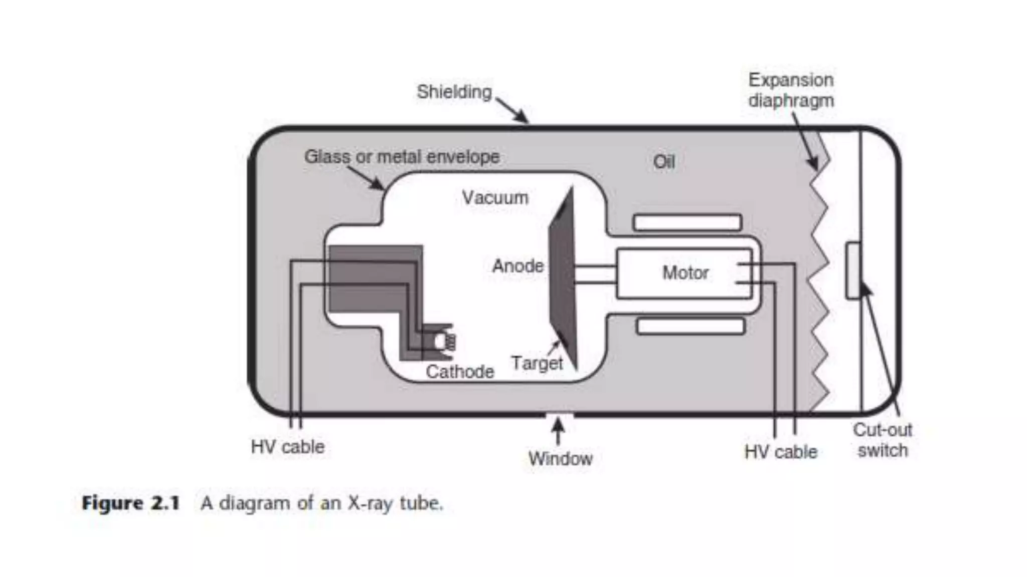


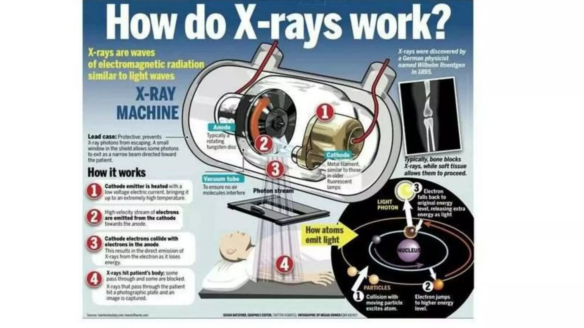
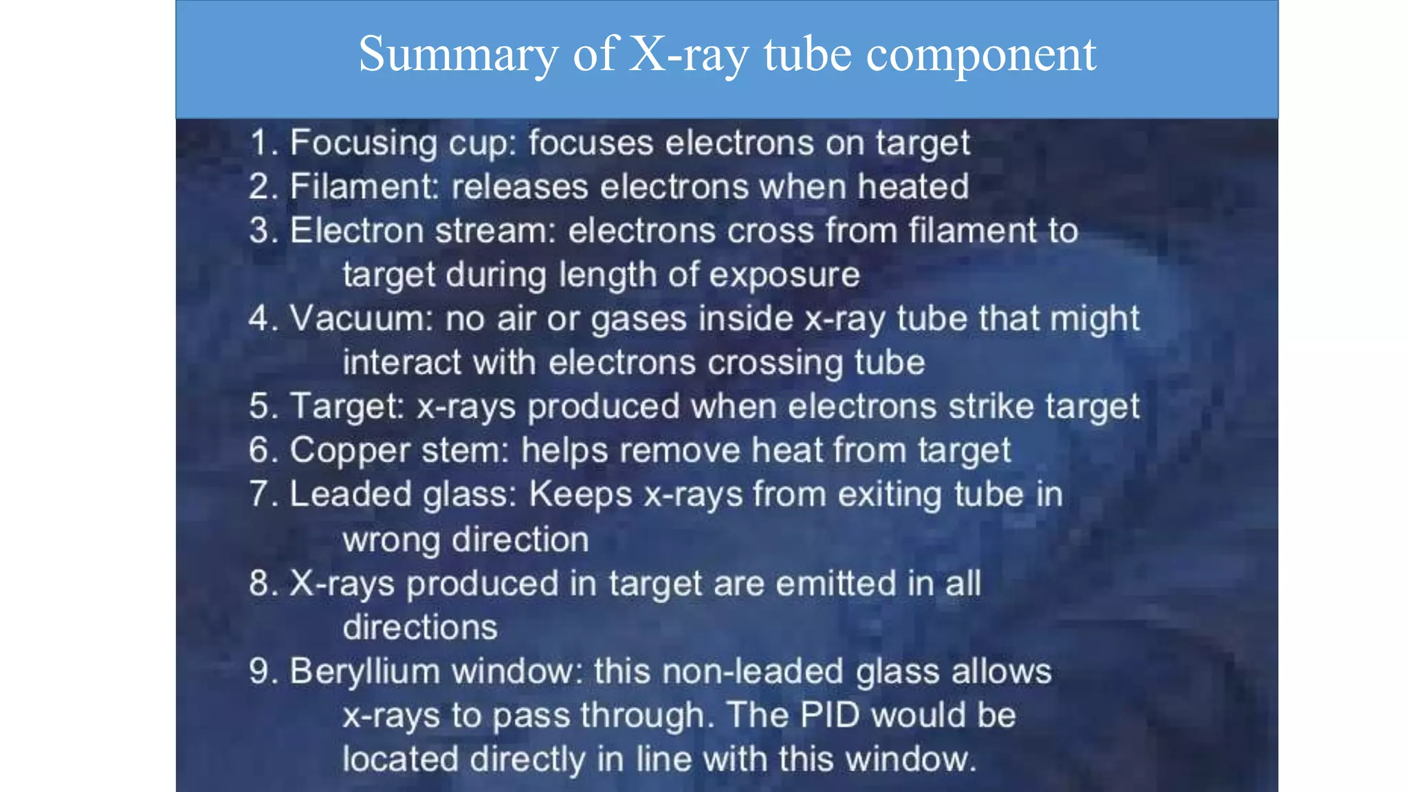

1. The document discusses the key components of an x-ray tube, including the filament, focusing cup, glass envelope, and tube housing. 2. The filament is made of tungsten wire and emits electrons through thermionic emission when heated. The focusing cup concentrates the electron beam. 3. The glass envelope encloses and evacuates the tube. It is made of borosilicate glass to withstand heat and maintain vacuum. The tube housing provides radiation shielding and insulation for the high voltages used.


