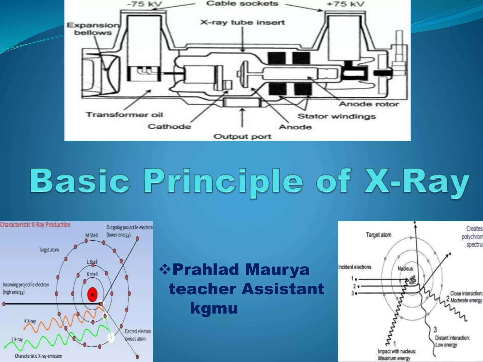
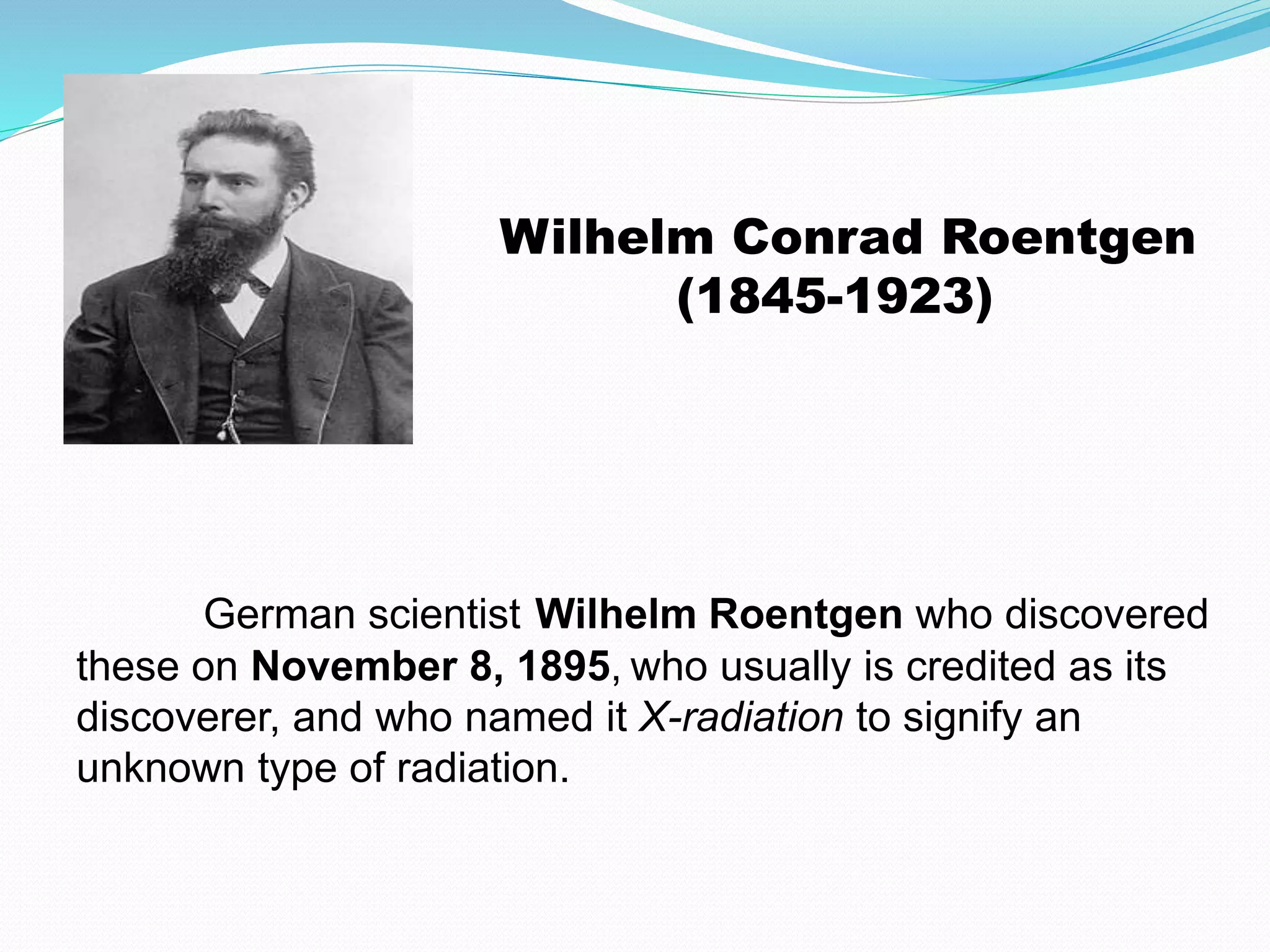
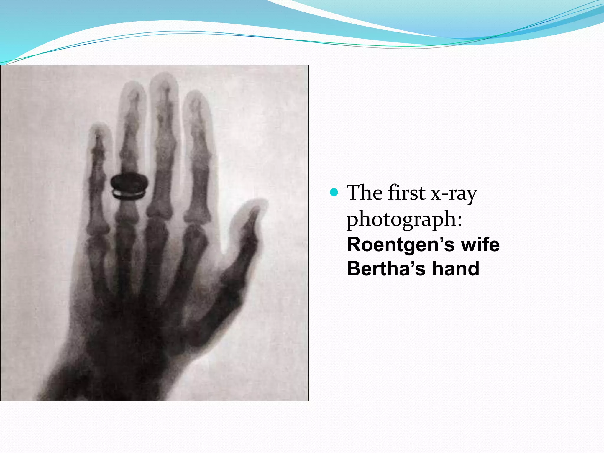
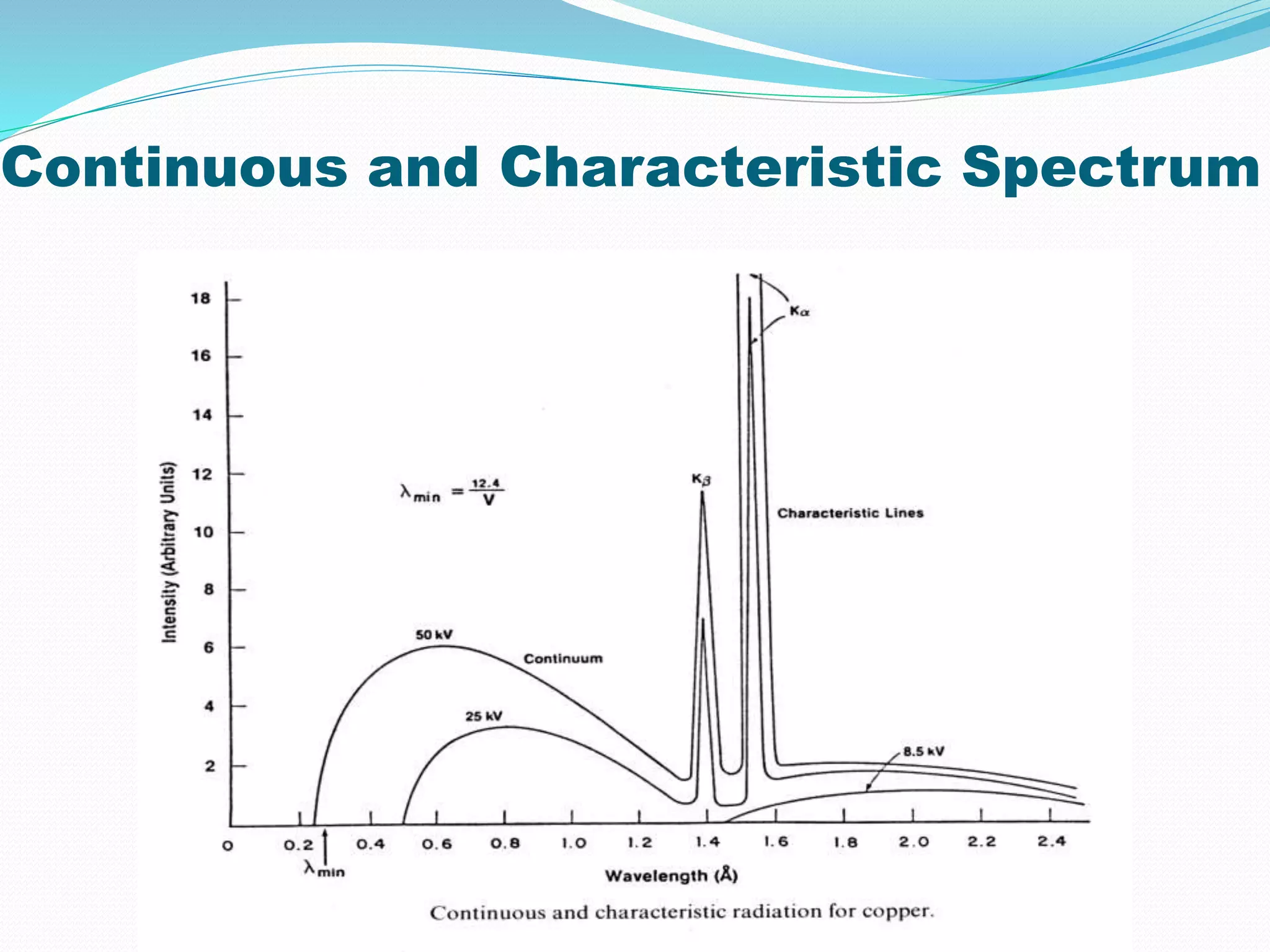
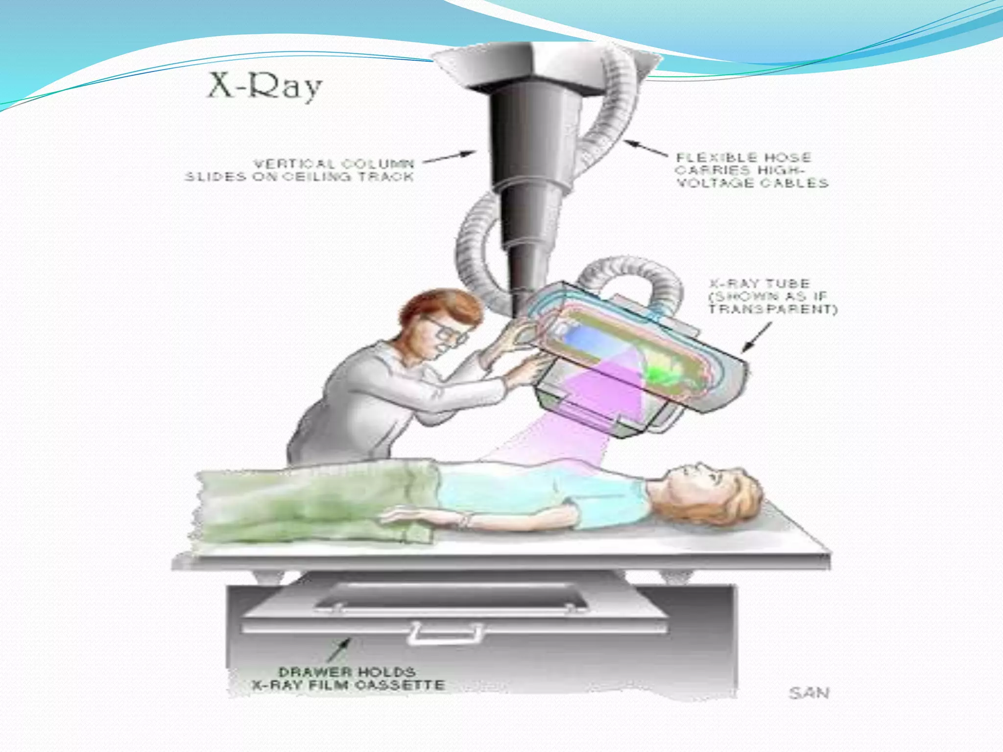
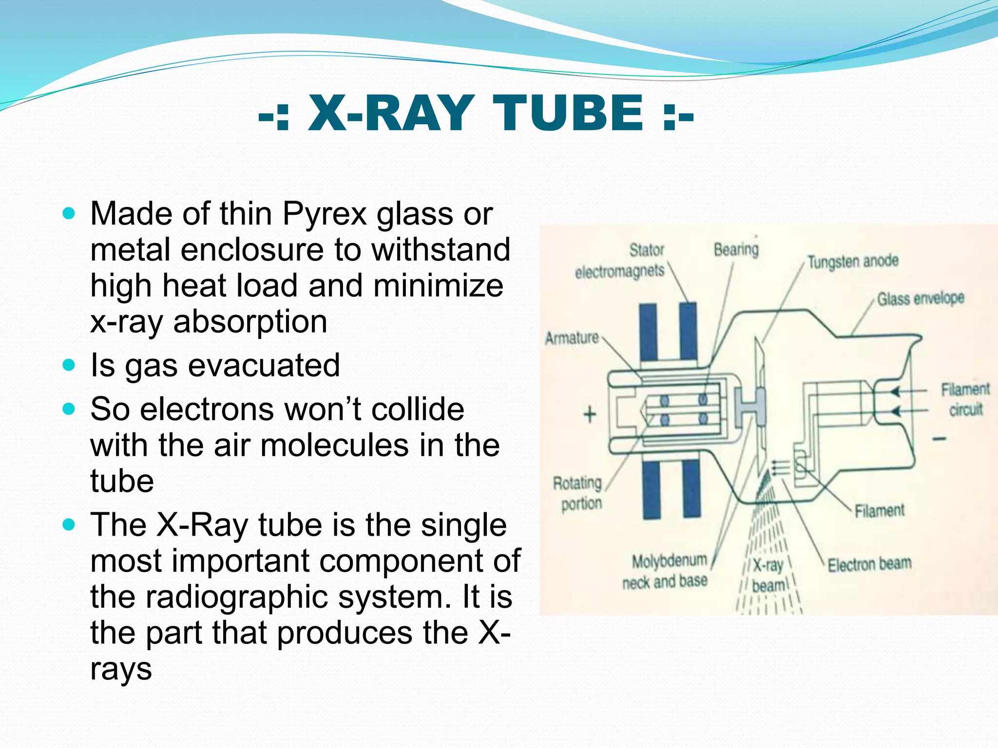
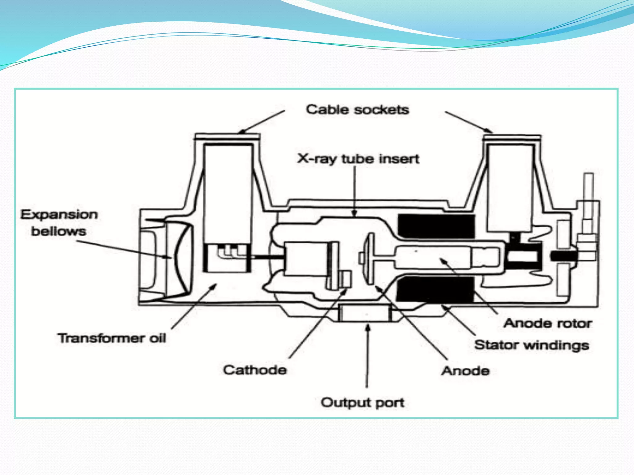
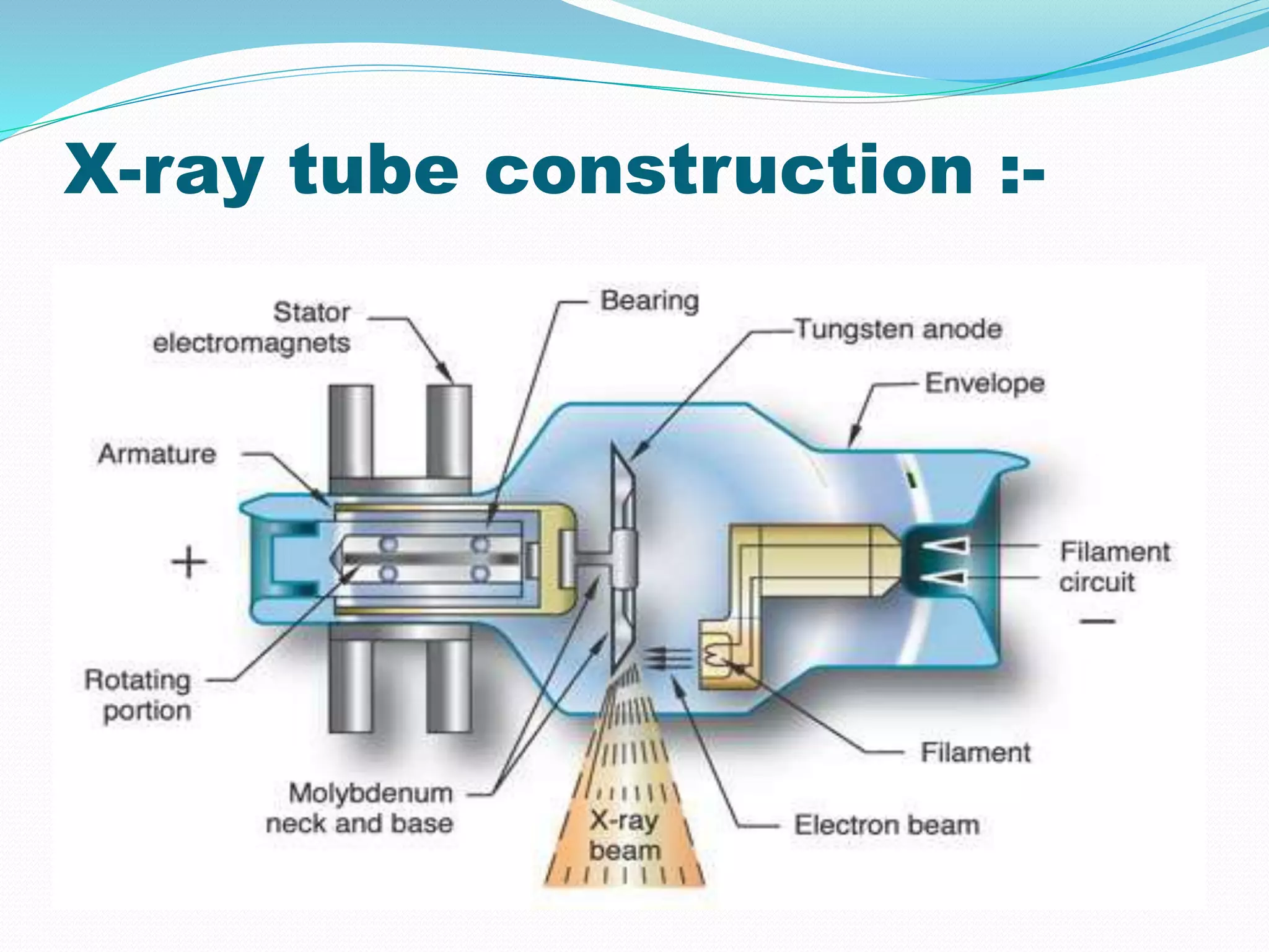
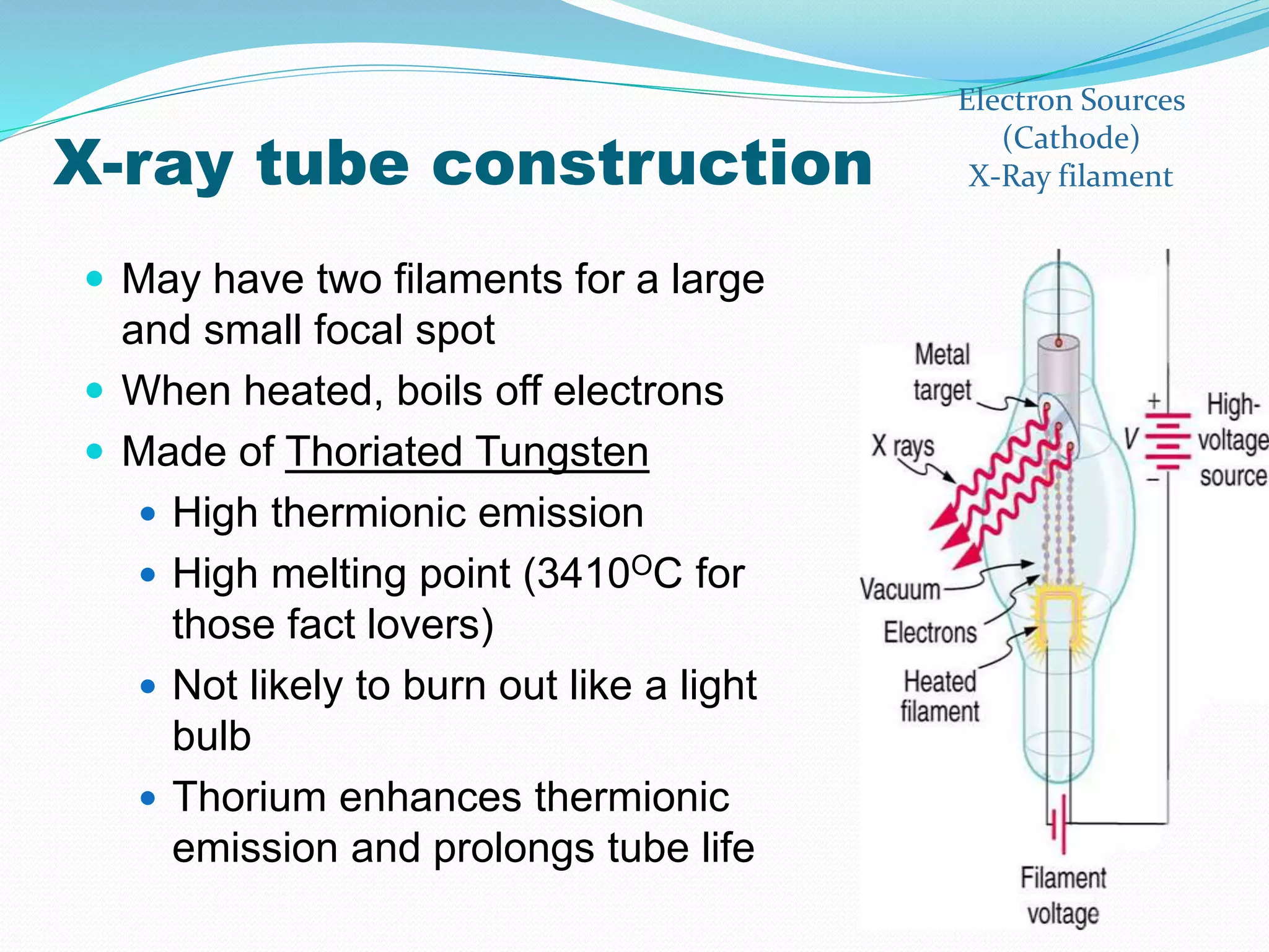
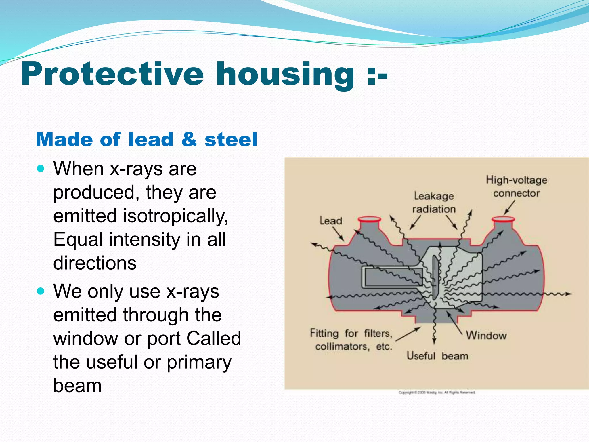
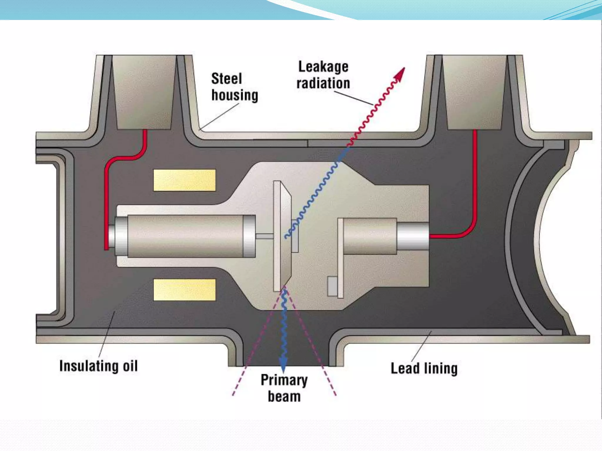
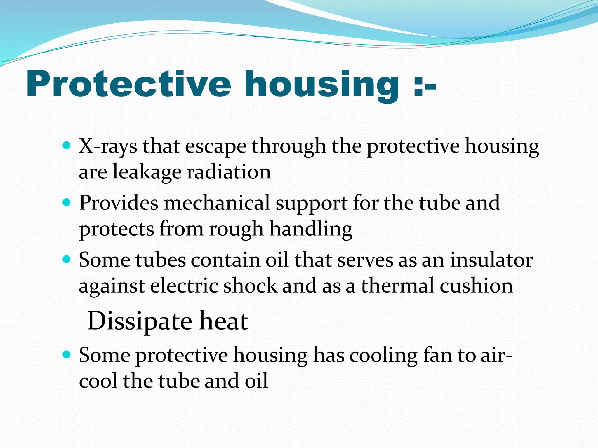
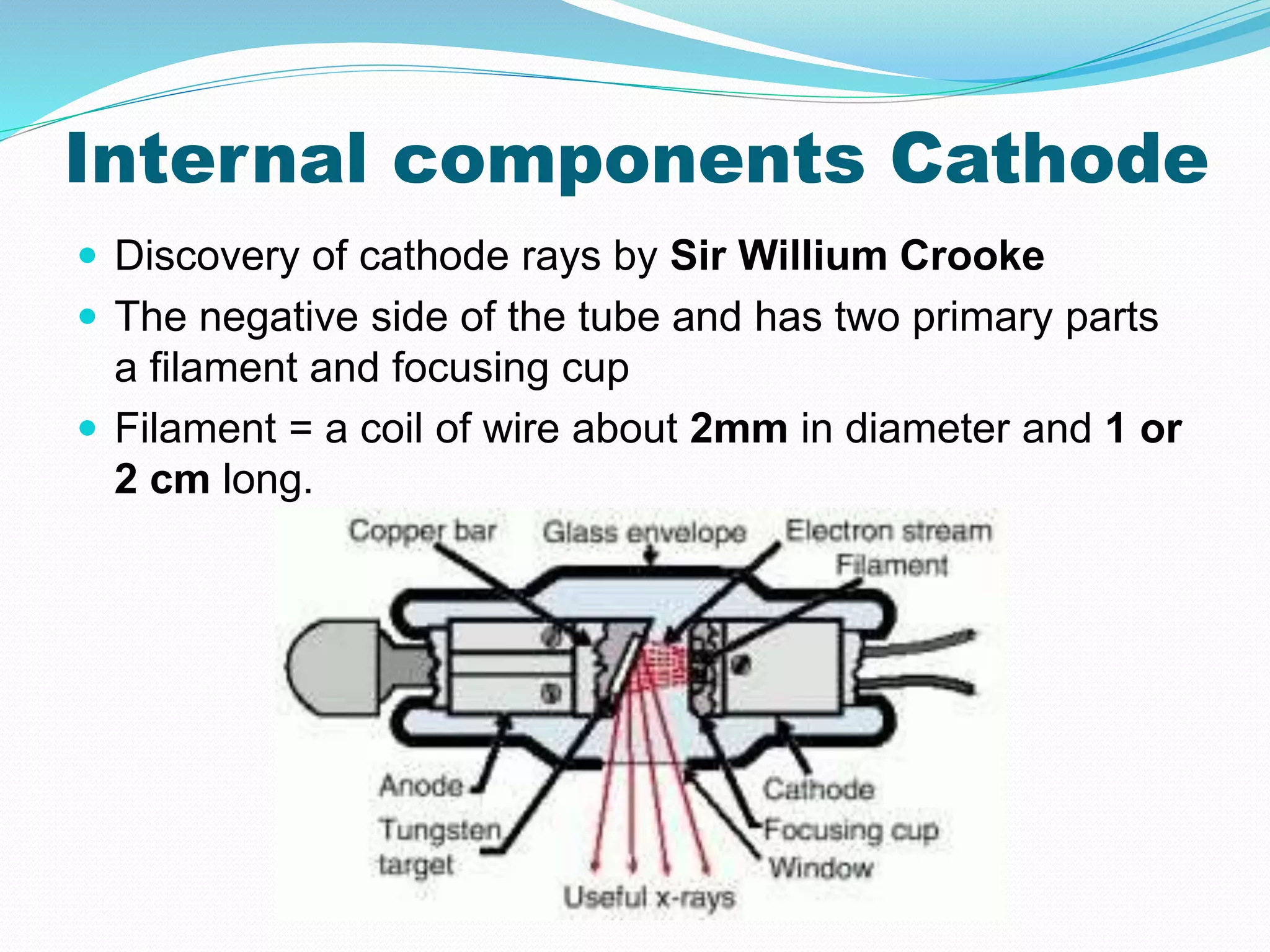
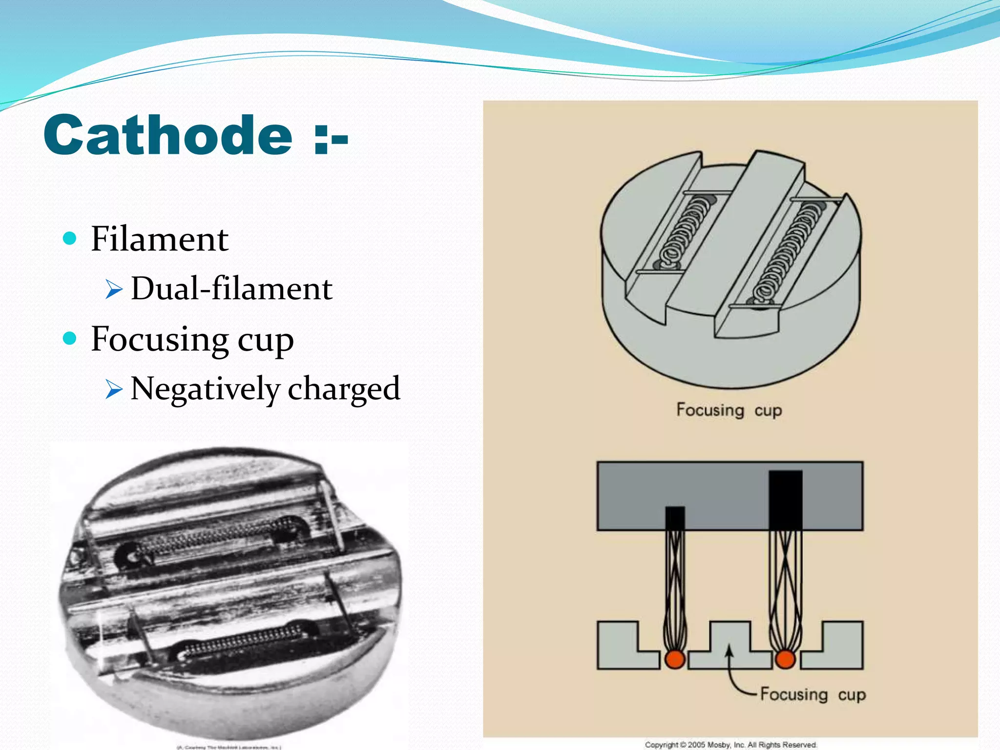
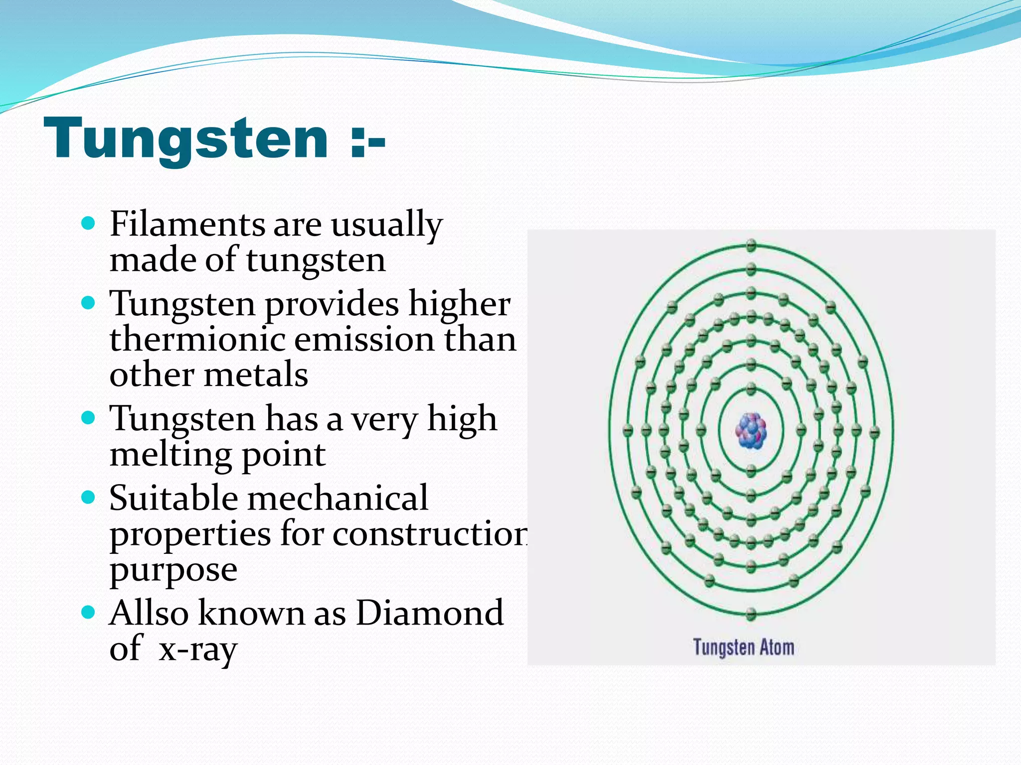
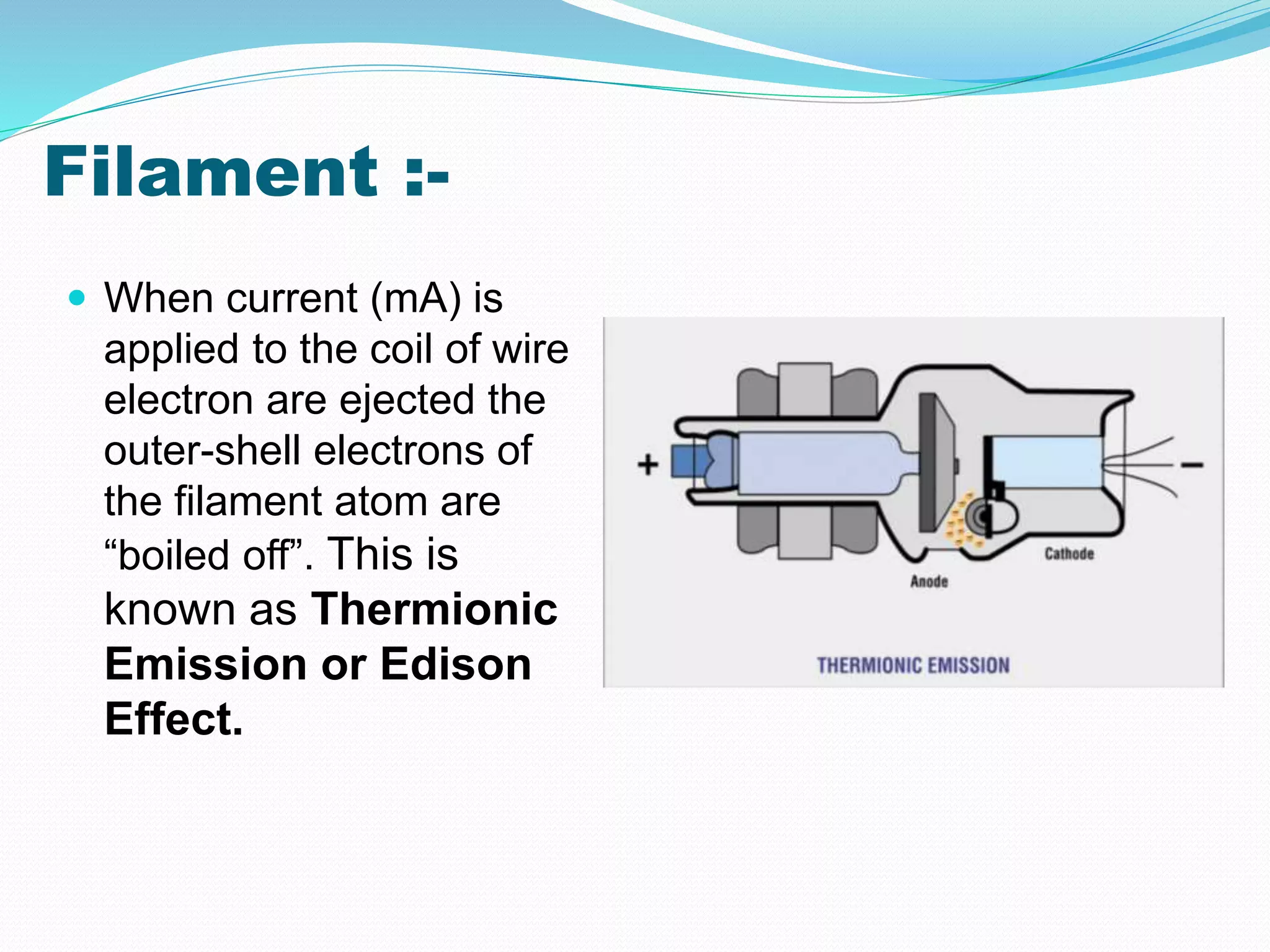
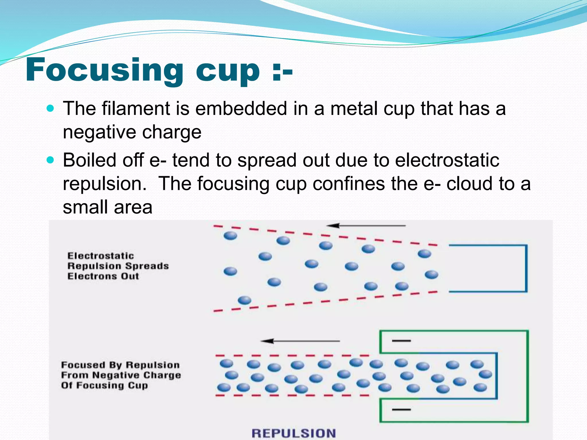
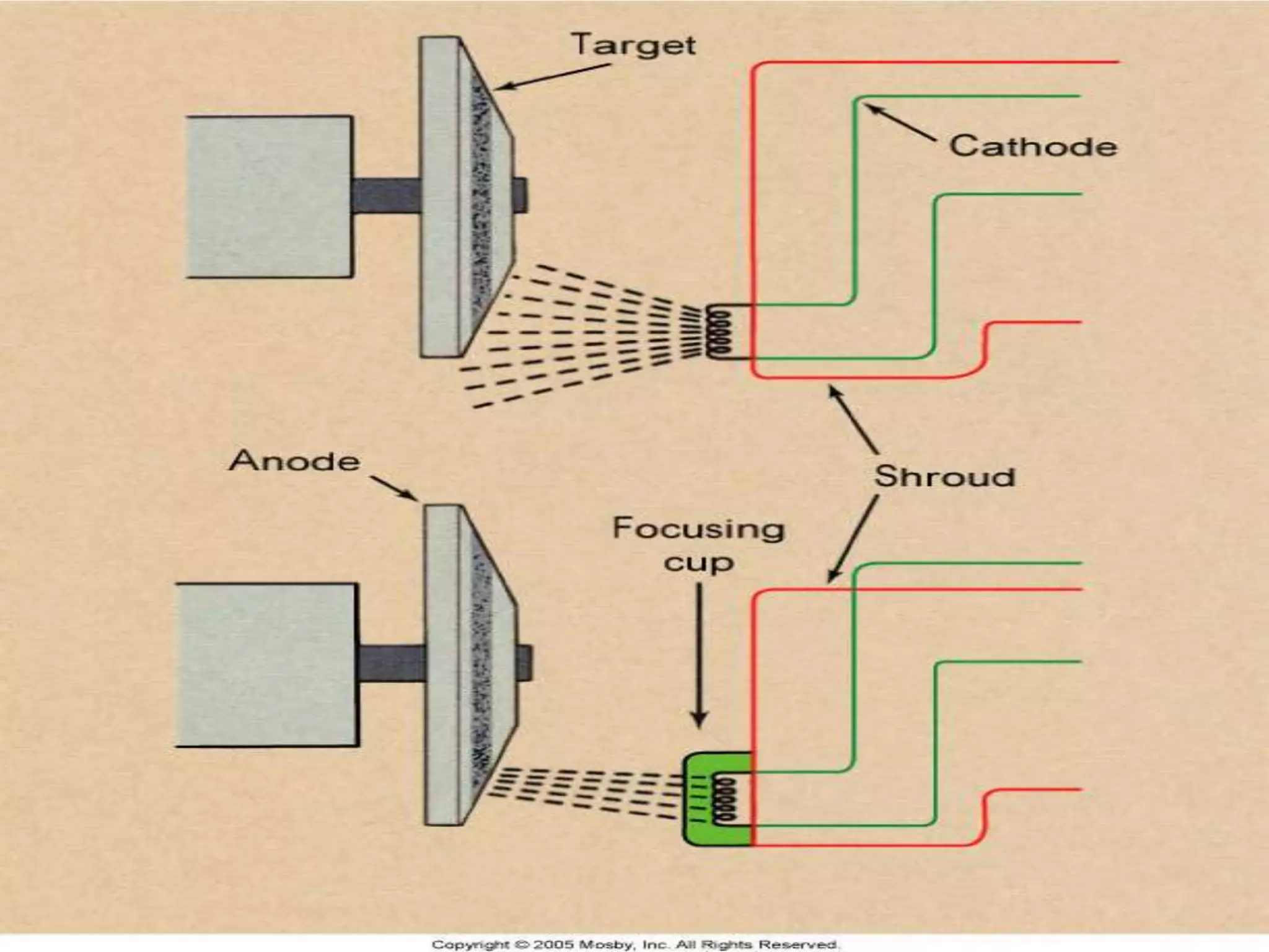
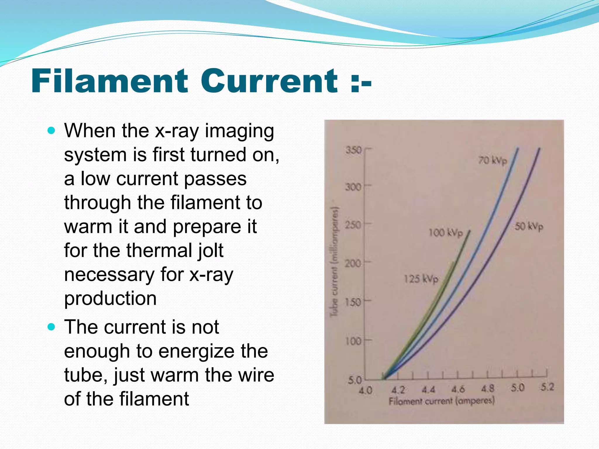
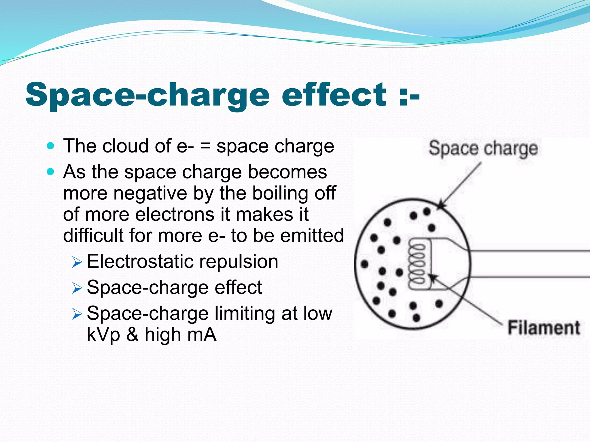
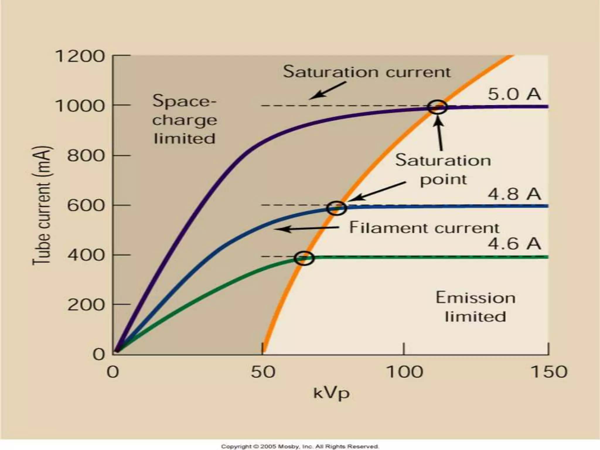
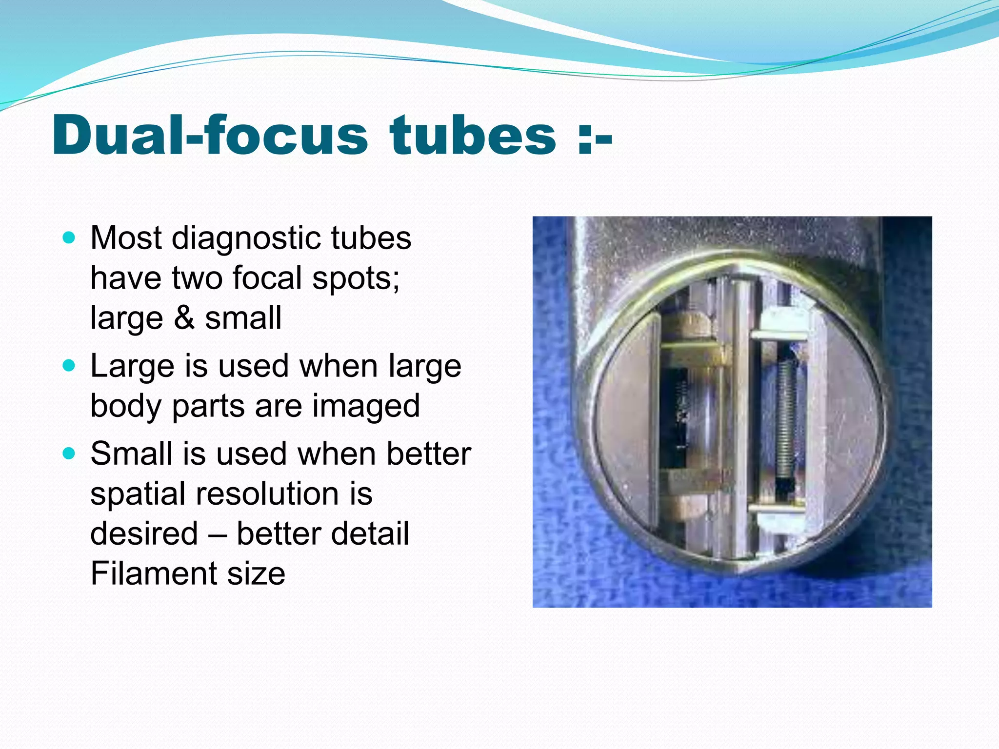
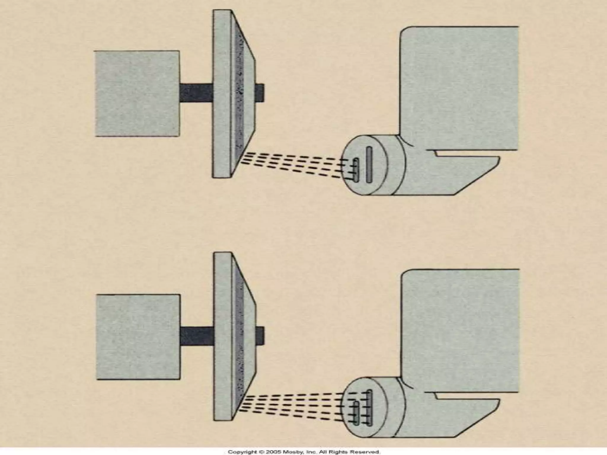
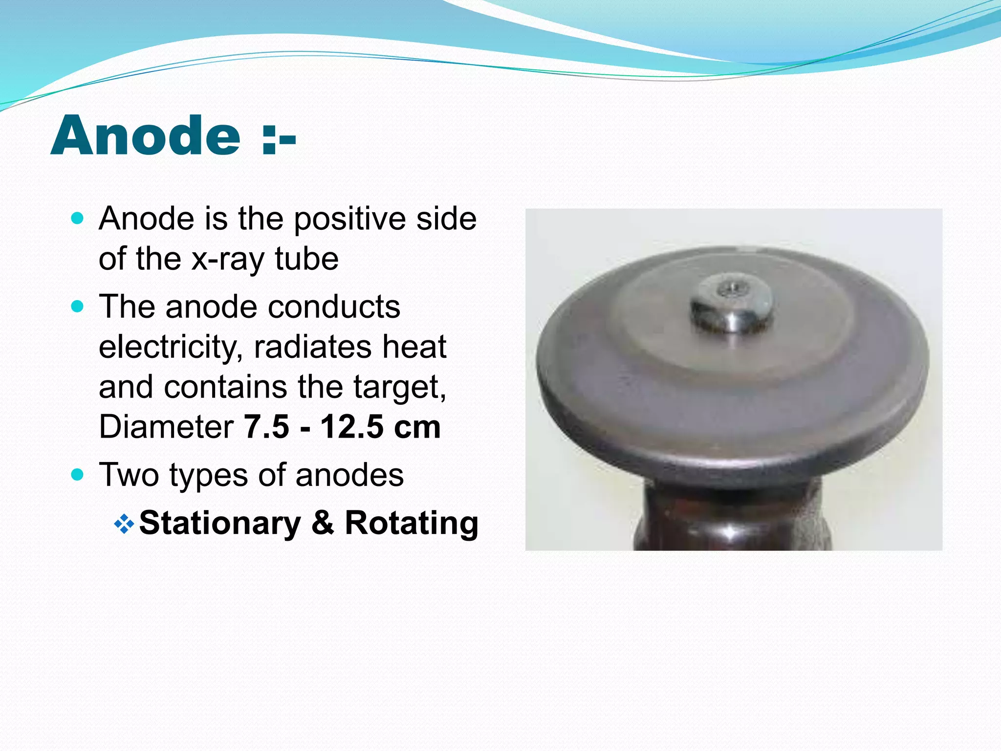
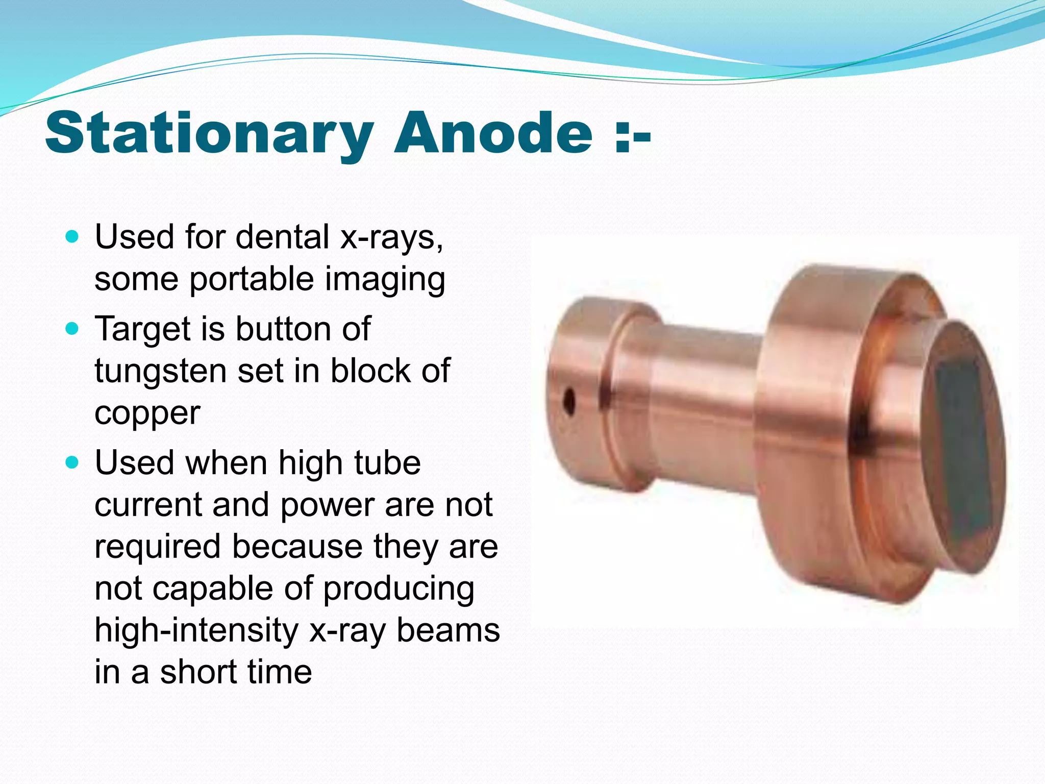
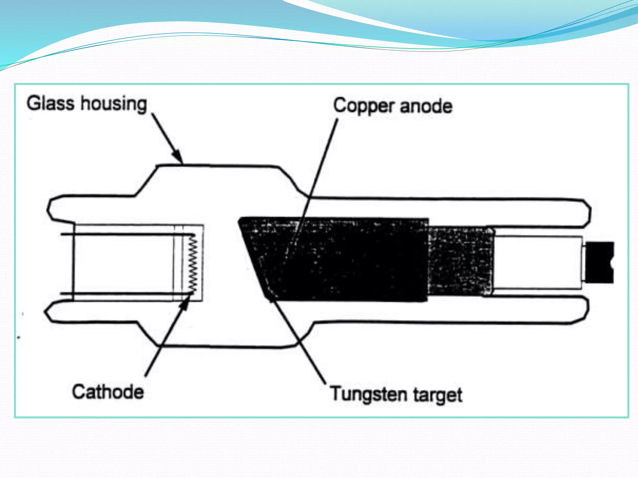
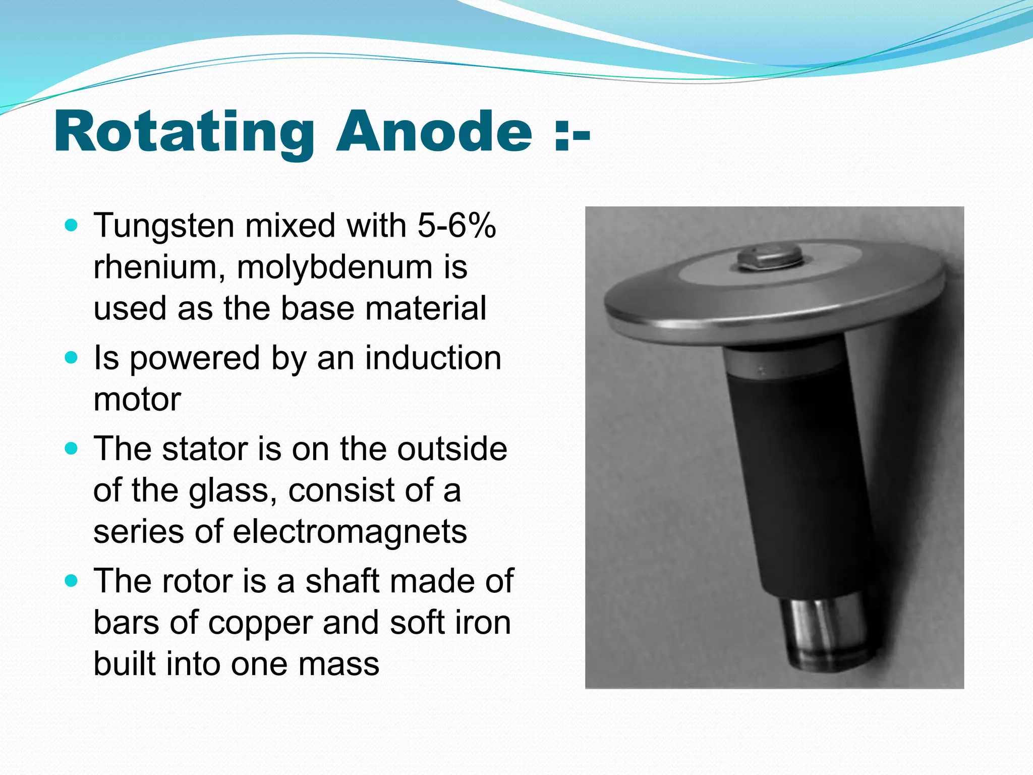
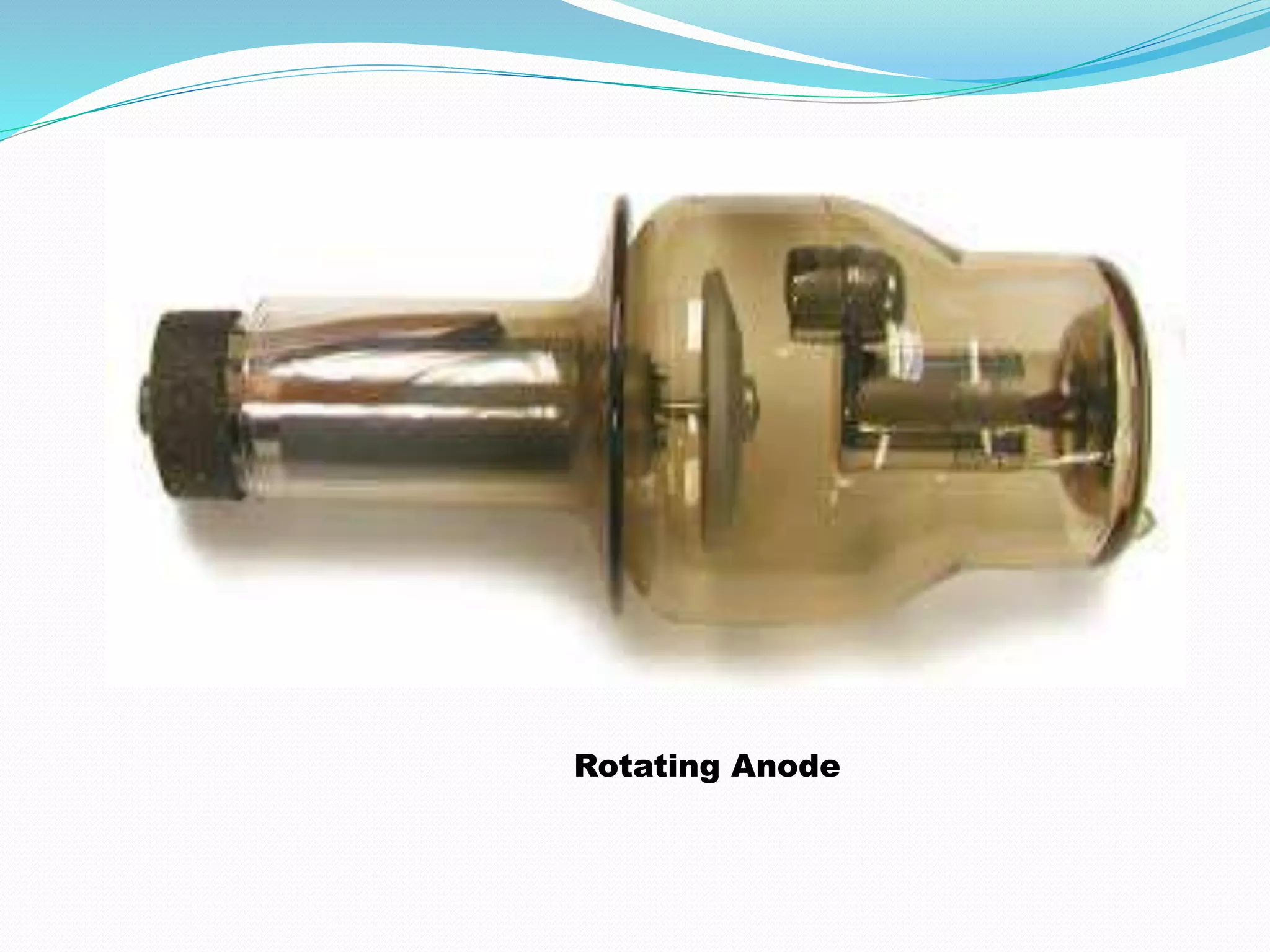
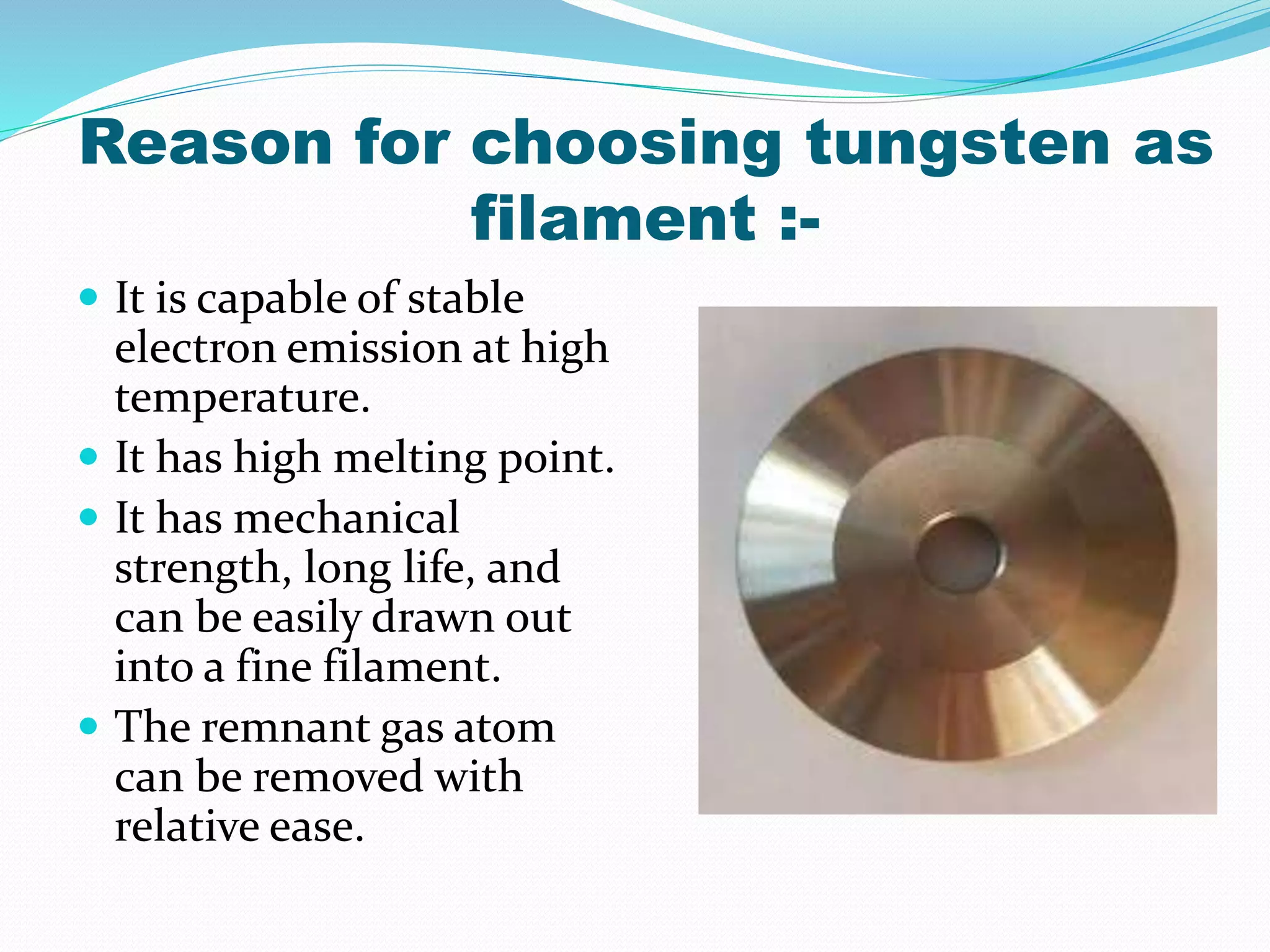
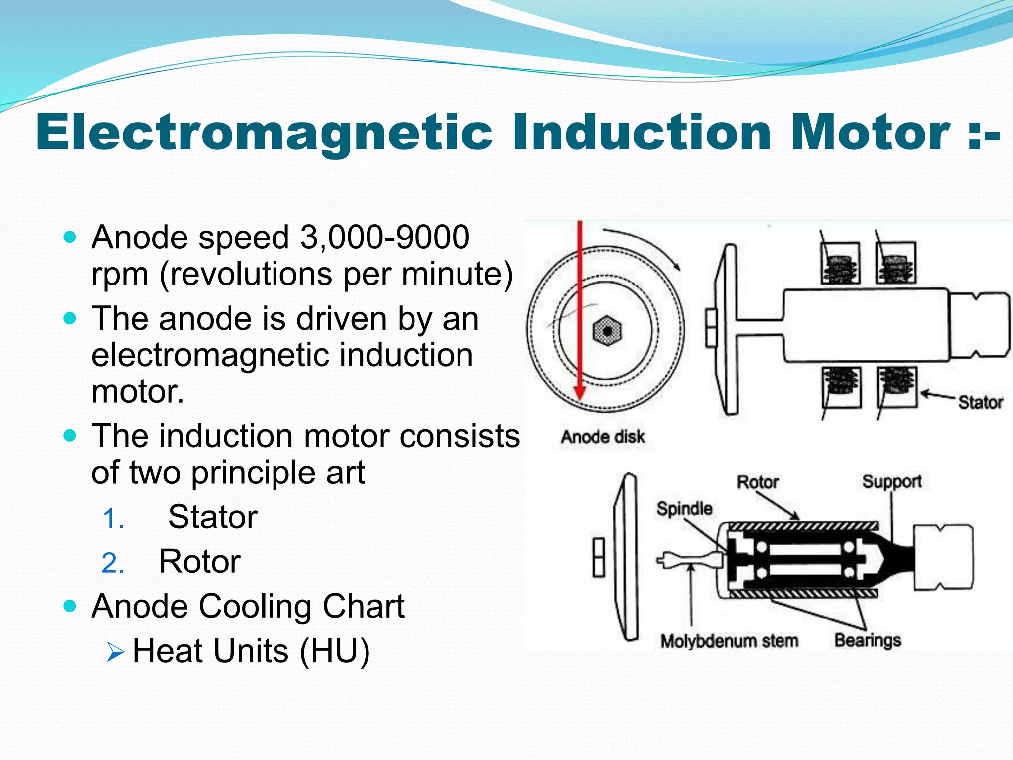
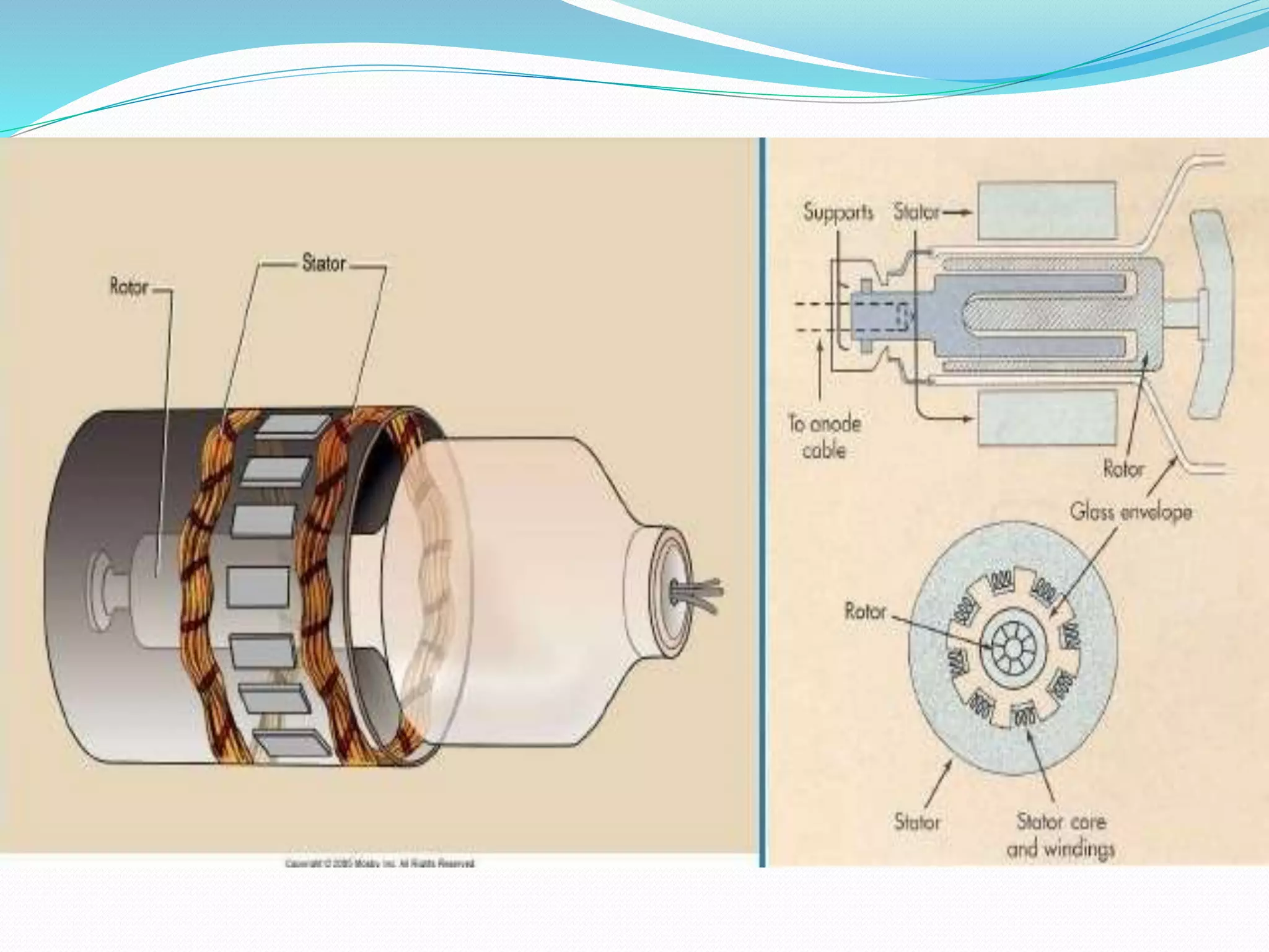
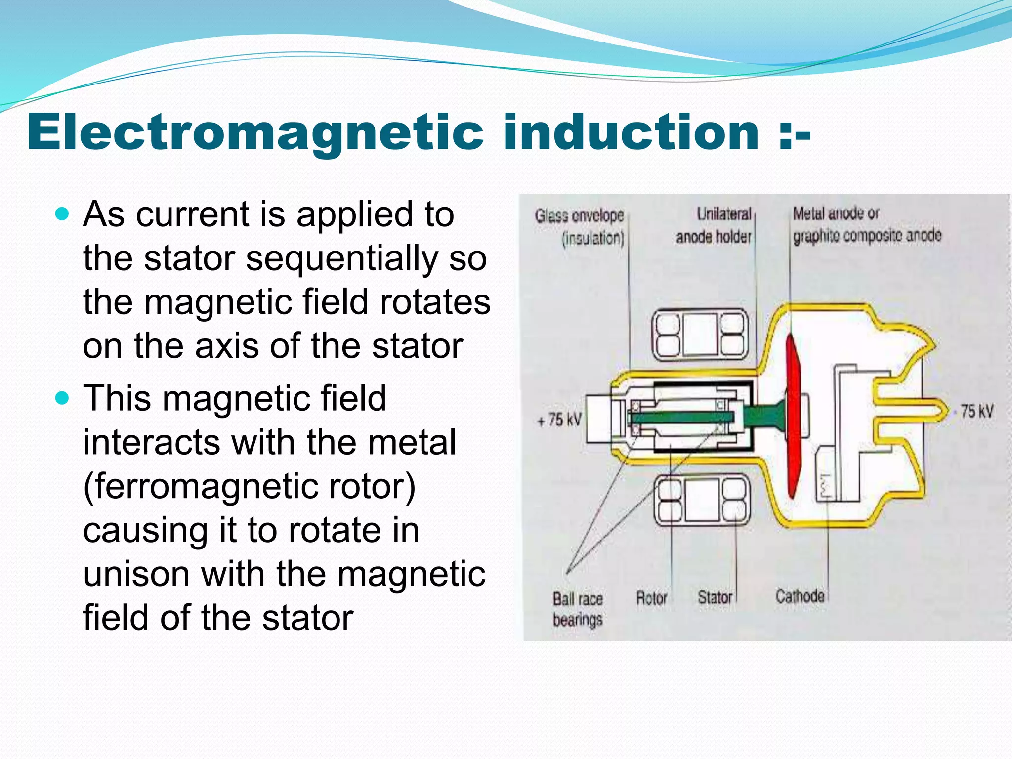
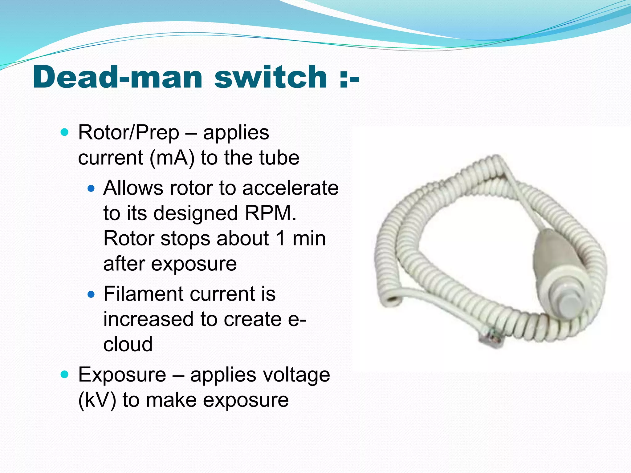
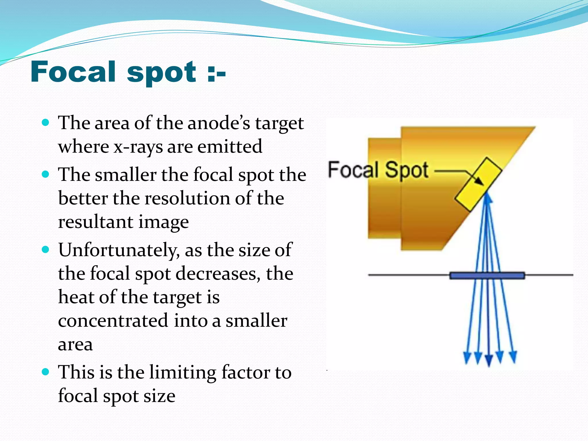
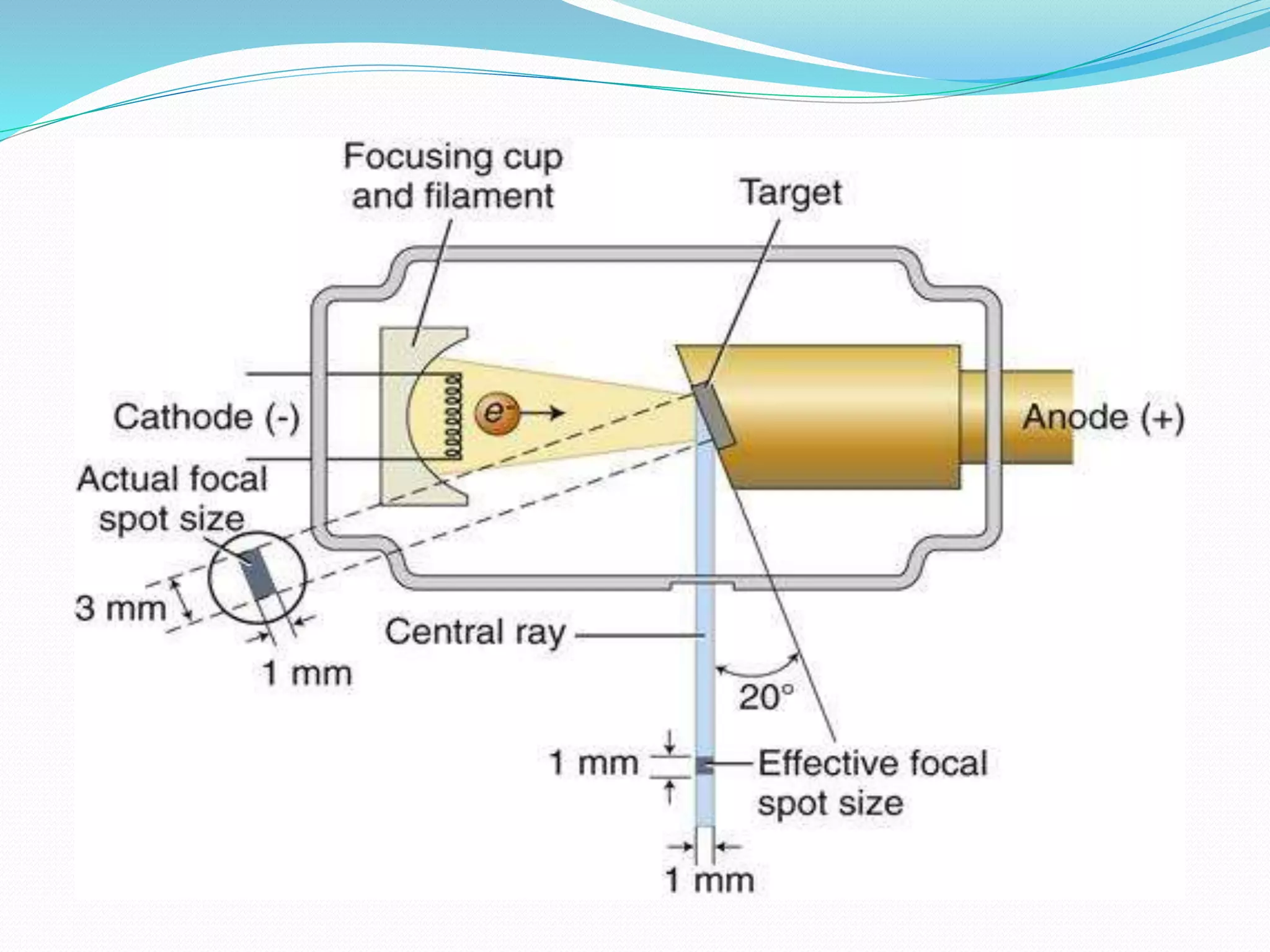
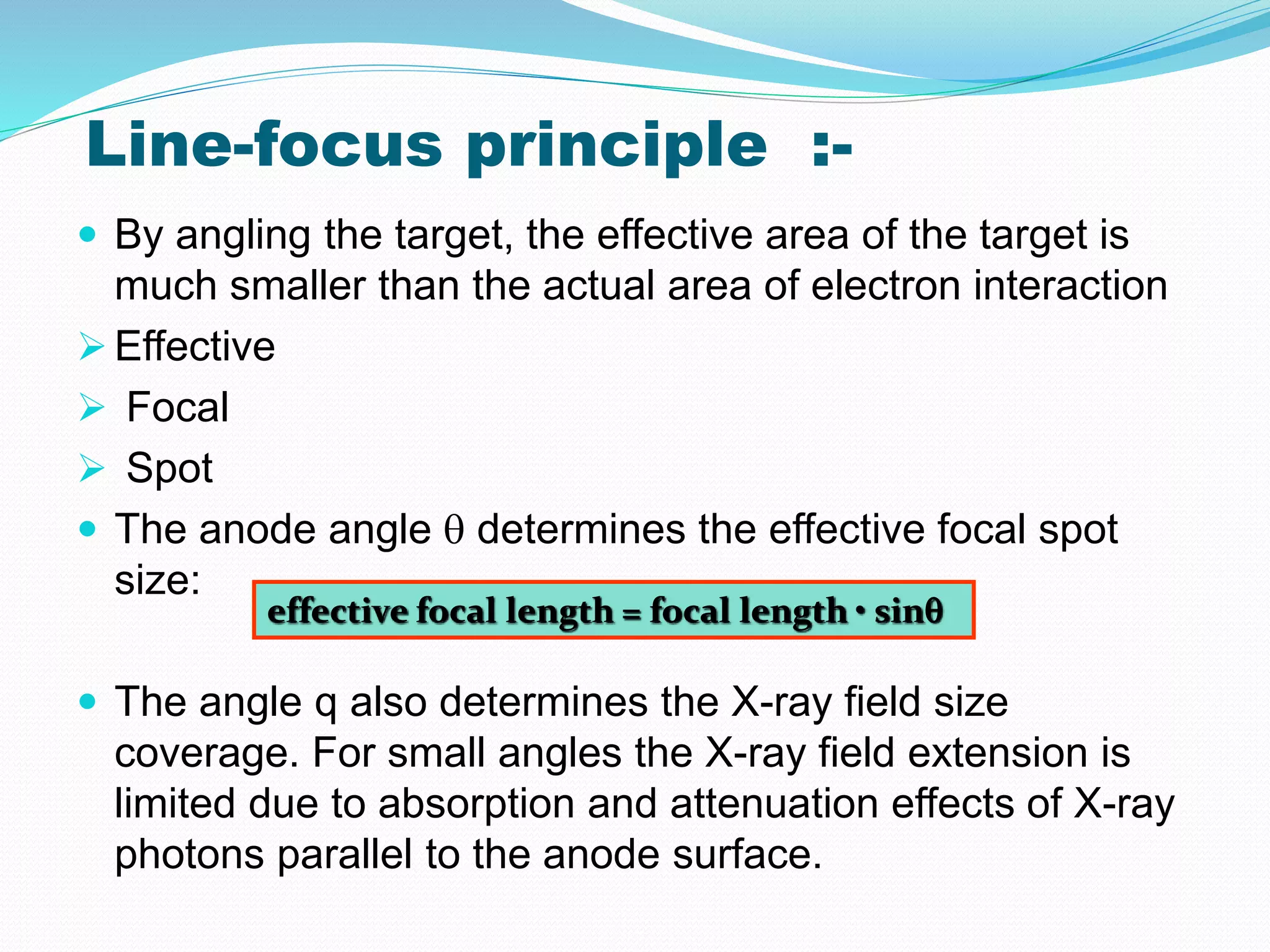
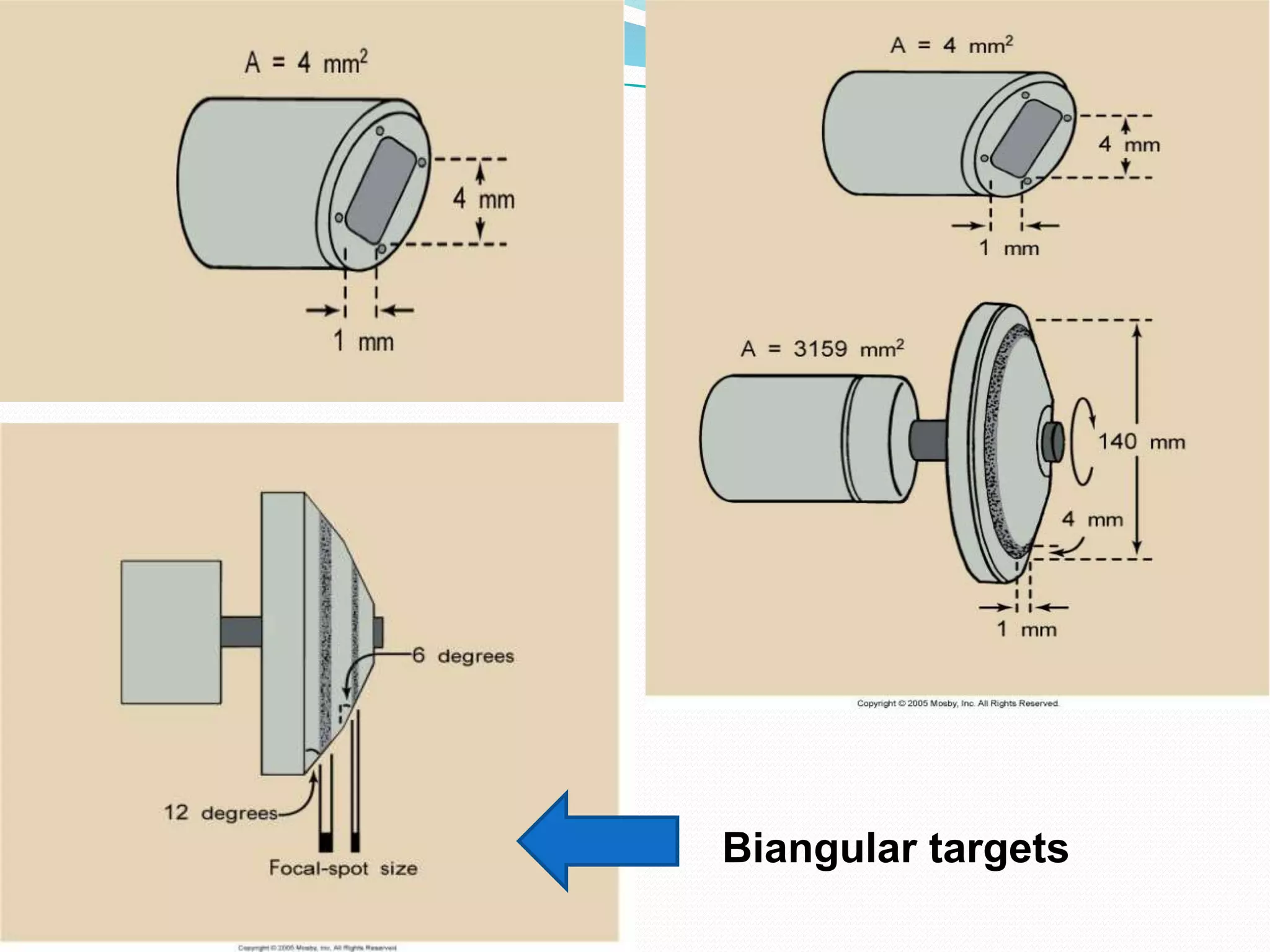
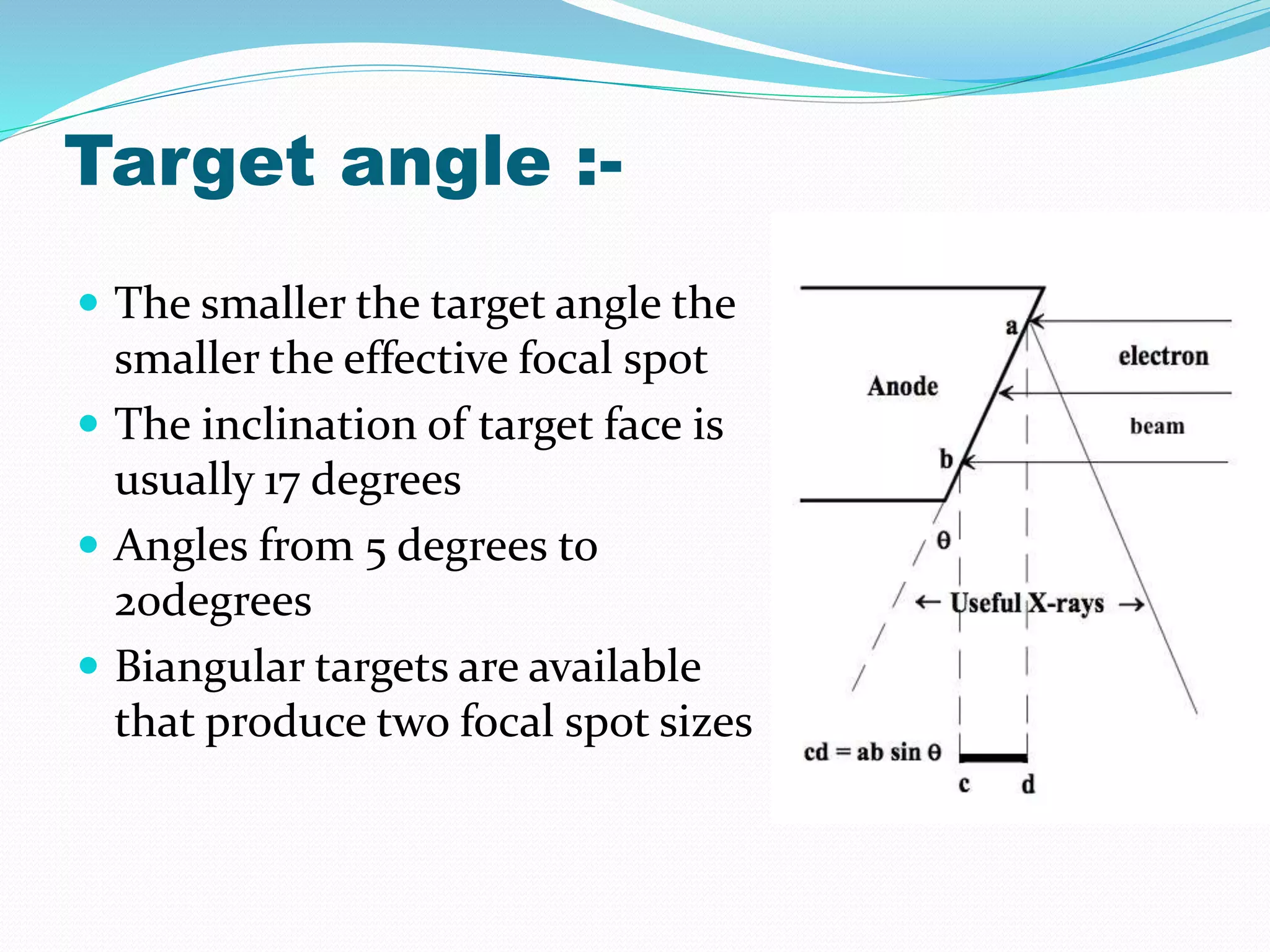
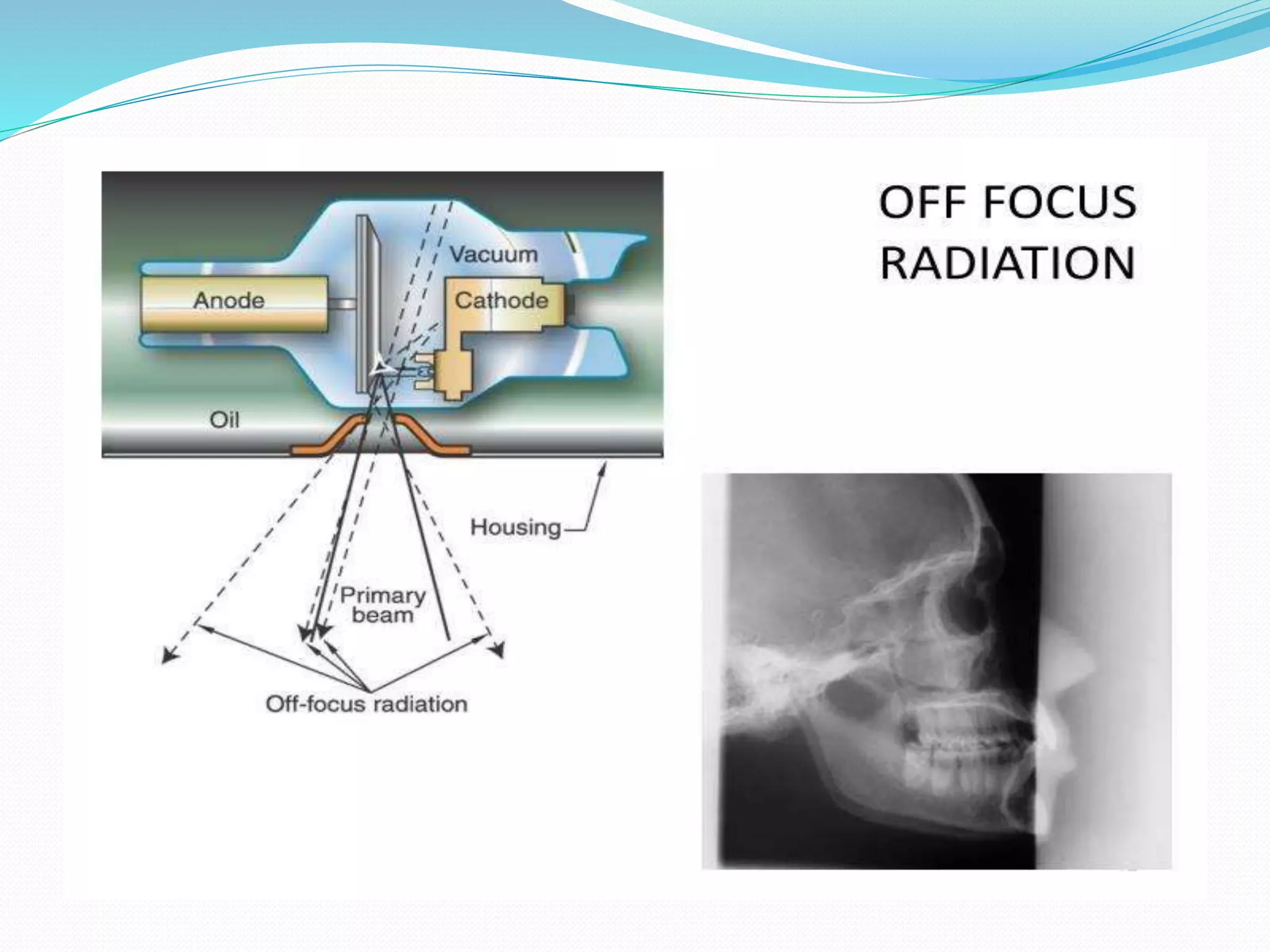
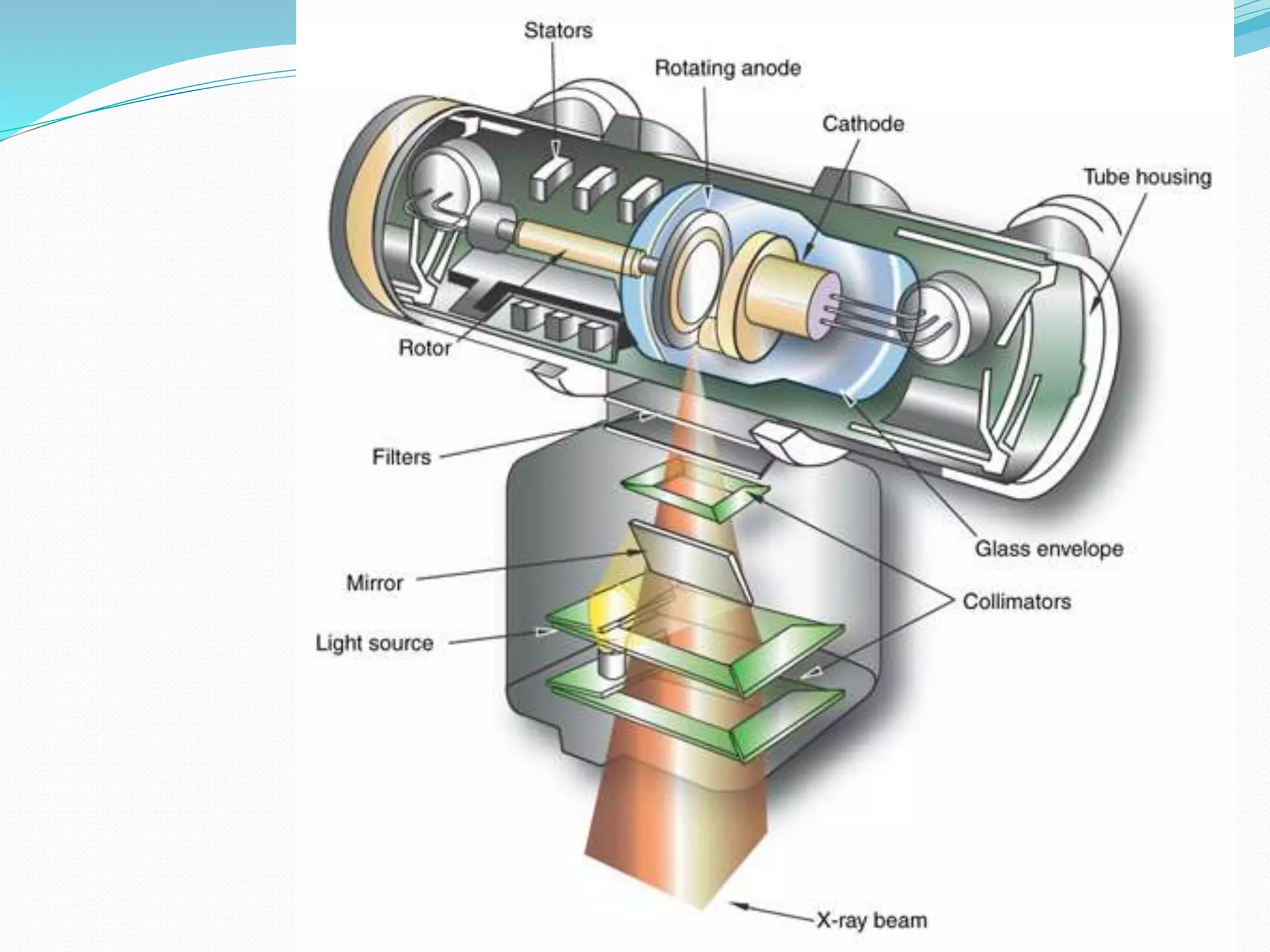
Prahlad Maurya
teacher Assistant
kgmu
Contents-
Introduction
History
Basic Physics of Radiation
 Continuous Spectrum
 X-ray tube
Wilhelm Conrad Roentgen
(1845-1923)
German scientist Wilhelm Roentgen who discovered
these on November 8, 1895, who usually is credited as its
discoverer, and who named it X-radiation to signify an
unknown type of radiation.
 The first x-ray
photograph:
Roentgen’s wife
Bertha’s hand
Basic x-ray physics :-
 X-rays: a form of electromagnetic
energy
 Travel at the speed of light
 Electromagnetic spectrum
 Gamma Rays
 X-rays
 Ultraviolet
 Visible light
 Infrared light
 Microwaves
 Radio waves
 Radar
Continuous Spectrum
 X-rays are produced whenever matter is irradiated
with a beam of high-energy charged particles or
photons
 In an x-ray tube, the interactions are between the
electrons and the target. Since energy must be
conserved, the energy loss from the interaction
results in the release of x-ray photons
 The energy (wavelength) will be equal to the energy
loss (Equation 4).
 This process generates a broad band of continuous
radiation (a.k.a. bremsstrahlung or white radiation)
Continuous Spectrum
 The minimum wavelength (
in angstroms) is dependent
on the accelerating potential
( in KV) of the electrons, by
the equation above.
 The continuum reaches a
maximum intensity at a
wavelength of about 1.5 to 2
times the min as indicated
by the shape of the curve
VV
hc 398.12
min 
Generating Characteristic Radiation
 The photoelectric effect is
responsible for generation of
characteristic x-rays. Qualitatively
here’s what is happening:
 An incoming high-energy
photoelectron disloges a k-shell
electron in the target, leaving a
vacancy in the shell
 An outer shell electron then
“jumps” to fill the vacancy
 A characteristic x-ray (equivalent
to the energy change in the
“jump”) is generated
L-shell to K-shell jump produces
a K x-ray
M-shell to K-shell jump produces
a K x-ray
Continuous and Characteristic Spectrum
-: X-RAY TUBE :-
 Made of thin Pyrex glass or
metal enclosure to withstand
high heat load and minimize
x-ray absorption
 Is gas evacuated
 So electrons won’t collide
with the air molecules in the
tube
 The X-Ray tube is the single
most important component of
the radiographic system. It is
the part that produces the X-
rays
X-ray tube construction :-
X-ray tube construction
 May have two filaments for a large
and small focal spot
 When heated, boils off electrons
 Made of Thoriated Tungsten
 High thermionic emission
 High melting point (3410OC for
those fact lovers)
 Not likely to burn out like a light
bulb
 Thorium enhances thermionic
emission and prolongs tube life
Electron Sources
(Cathode)
X-Ray filament
Protective housing :-
Made of lead & steel
 When x-rays are
produced, they are
emitted isotropically,
Equal intensity in all
directions
 We only use x-rays
emitted through the
window or port Called
the useful or primary
beam
Protective housing :-
 X-rays that escape through the protective housing
are leakage radiation
 Provides mechanical support for the tube and
protects from rough handling
 Some tubes contain oil that serves as an insulator
against electric shock and as a thermal cushion
Dissipate heat
 Some protective housing has cooling fan to air-
cool the tube and oil
Internal components Cathode
 Discovery of cathode rays by Sir Willium Crooke
 The negative side of the tube and has two primary parts
a filament and focusing cup
 Filament = a coil of wire about 2mm in diameter and 1 or
2 cm long.
Cathode :-
 Filament
 Dual-filament
 Focusing cup
 Negatively charged
Tungsten :-
 Filaments are usually
made of tungsten
 Tungsten provides higher
thermionic emission than
other metals
 Tungsten has a very high
melting point
 Suitable mechanical
properties for construction
purpose
 Allso known as Diamond
of x-ray
Filament :-
 When current (mA) is
applied to the coil of wire
electron are ejected the
outer-shell electrons of
the filament atom are
“boiled off”. This is
known as Thermionic
Emission or Edison
Effect.
Focusing cup :-
 The filament is embedded in a metal cup that has a
negative charge
 Boiled off e- tend to spread out due to electrostatic
repulsion. The focusing cup confines the e- cloud to a
small area
Filament Current :-
 When the x-ray imaging
system is first turned on,
a low current passes
through the filament to
warm it and prepare it
for the thermal jolt
necessary for x-ray
production
 The current is not
enough to energize the
tube, just warm the wire
of the filament
Space-charge effect :-
 The cloud of e- = space charge
 As the space charge becomes
more negative by the boiling off
of more electrons it makes it
difficult for more e- to be emitted
 Electrostatic repulsion
 Space-charge effect
 Space-charge limiting at low
kVp & high mA
Dual-focus tubes :-
 Most diagnostic tubes
have two focal spots;
large & small
 Large is used when large
body parts are imaged
 Small is used when better
spatial resolution is
desired – better detail
Filament size
Anode :-
 Anode is the positive side
of the x-ray tube
 The anode conducts
electricity, radiates heat
and contains the target,
Diameter 7.5 - 12.5 cm
 Two types of anodes
Stationary & Rotating
Stationary Anode :-
 Used for dental x-rays,
some portable imaging
 Target is button of
tungsten set in block of
copper
 Used when high tube
current and power are not
required because they are
not capable of producing
high-intensity x-ray beams
in a short time
S
T
A
T
I
O
N
A
R
Y
ANODE
Rotating Anode :-
 Tungsten mixed with 5-6%
rhenium, molybdenum is
used as the base material
 Is powered by an induction
motor
 The stator is on the outside
of the glass, consist of a
series of electromagnets
 The rotor is a shaft made of
bars of copper and soft iron
built into one mass
Rotating Anode
Reason for choosing tungsten as
filament :-
 It is capable of stable
electron emission at high
temperature.
 It has high melting point.
 It has mechanical
strength, long life, and
can be easily drawn out
into a fine filament.
 The remnant gas atom
can be removed with
relative ease.
Electromagnetic Induction Motor :-
 Anode speed 3,000-9000
rpm (revolutions per minute)
 The anode is driven by an
electromagnetic induction
motor.
 The induction motor consists
of two principle art
1. Stator
2. Rotor
 Anode Cooling Chart
 Heat Units (HU)
Electromagnetic induction :-
 As current is applied to
the stator sequentially so
the magnetic field rotates
on the axis of the stator
 This magnetic field
interacts with the metal
(ferromagnetic rotor)
causing it to rotate in
unison with the magnetic
field of the stator
Dead-man switch :-
 Rotor/Prep – applies
current (mA) to the tube
 Allows rotor to accelerate
to its designed RPM.
Rotor stops about 1 min
after exposure
 Filament current is
increased to create e-
cloud
 Exposure – applies voltage
(kV) to make exposure
Focal spot :-
 The area of the anode’s target
where x-rays are emitted
 The smaller the focal spot the
better the resolution of the
resultant image
 Unfortunately, as the size of
the focal spot decreases, the
heat of the target is
concentrated into a smaller
area
 This is the limiting factor to
focal spot size
Line-focus principle :-
 By angling the target, the effective area of the target is
much smaller than the actual area of electron interaction
 Effective
 Focal
 Spot
 The anode angle q determines the effective focal spot
size:
 The angle q also determines the X-ray field size
coverage. For small angles the X-ray field extension is
limited due to absorption and attenuation effects of X-ray
photons parallel to the anode surface.
effective focal length = focal length • sinq
Biangular targets
Target angle :-
 The smaller the target angle the
smaller the effective focal spot
 The inclination of target face is
usually 17 degrees
 Angles from 5 degrees to
20degrees
 Biangular targets are available
that produce two focal spot sizes
Anode Heel Effect :-
 Because of the use of line-focus principle the
consequence is that the radiation intensity on the
cathode side of the x-ray field is higher than that on
the anode side
 Because the e- on the anode side must travel
further than the e- that are close to the cathode side
of the target, the anode side x-rays have slightly
lower energy than the cathode side x-rays
 The smaller the anode
angle, the larger the
heel affect
 Better use anode heal
effect for AP view of
thoracic spine x-ray
Anode Heel Effect :-
Extra focal Radiation :-
 X-ray tubes are designed so that
the projectile e- interacts with the
target. However, some of the e-
bounce off the target and land on
other areas
 This caused x-rays to be
produced out side the focal spot
 These rays can also be called
off-focus radiation
 Extra focal radiation is
undesirable because it extends
the size of the focal spot,
increases patient skin dose &
reduces image contrast
Fixed diaphragm in the tube
housing :-
 Using a grid
does not reduce
extra focal
radiation
The Control Console :-
 The control console
is device that allows
the technologist to
set technical factors
(mAs & kVp) and to
make an exposure.
 Only a legally
licensed individual is
authorized to
energize the console.
kVp = Energy mAs = Amount
Kilovoltage Peak :-
 kVp
 kVp= controls contrast (differences from black to white)
 One kilovolt is = to 1000 volts
 The amount of voltage selected for the x-ray tube
 Range 45 to 120 kVp (diagnostic range)
 kVp controls contrast
 Determine the energy of electron
 Higher kVp then higher energy of x-ray
 kVp is direct proportional of velocity of electron
 220Volts incoming – up to 120,000 volts (120kVp) to anode
side of x-ray tube
Milliampere :-
 mAs
 One milliampere is equal to one thousandth of an
ampere.
 The amount of current supplied to the x-ray tube
 Range 10 to 1200 mA
Time :-
 In seconds
 How long x-rays will be produced
 0.001 to 6 seconds
Milliampere seconds :-
 mAs
 mAs – density (Amount of black on the film)
 Greater mAs, more then electron produce
 mAs is direct proportional of current
 Voltage current is reduced to milliamps to the filament
(cathode) side of the tube.
mA X s = mAs
How do x-rays passing through the body
create an image?
 X-rays that pass through the body render the image dark
(black)
 X-rays that are totally blocked render the image light
(white)
 Air = low atomic # = x-rays get through = image is dark
(black)
 Metal = high atomic # = x-rays blocked = image is light
(white)
5 Basic Radiographic Densities
 Air
 Fat
 Soft tissue/fluid
 Mineral
 Metal
Radiographic Analysis
 Any structure, normal or pathologic, should be
analyzed for:
1. Size
2. Shape and contour
3. Position
4. Density (You must know the 5 basic densities)
Operating Console
Operating Console
 All consoles have the same basic controls:
 On/Off Switch
 Kilovoltage control
 Milliampere control
 Length of exposure/timer
 Focal Spot Size
 Automatic Exposure Control
 Selection of appropriate chamber
 Density Controls
These are examples of manual
exposure controls. Anything not
performed with AEC is considered
a manual exposure. Your distal
extremities are manual exposure!
Manual Control
Automatic Exposure Control (AEC)
 Automatic Exposure Control is an automatic time that
detects the amount of radiation passing through the patient
and terminates the exposure after a appropriate amount of
time
 Minimum reaction (response) time is determined by the
length of time necessary to for the AEC to respond to the
radiation and for the generator to terminate the exposure.
 Backup time is set at 150% (1.5 times) that of the anticipated
manual exposure.
 If exposure is expected to be 75 kV at 100 mAs, it will terminate
at 150 mAs.
 Most common and popular AEC device is the three
chambers:
***Remember the selection
of an incorrect chamber
can cause an over or
underexposed image!!!
THANK YOU
 The goal of the education is the
advancement of knowledge and
the dissemination of truth.

Basic principle of x ray

  • 1.
  • 2.
    Contents- Introduction History Basic Physics ofRadiation  Continuous Spectrum  X-ray tube
  • 3.
    Wilhelm Conrad Roentgen (1845-1923) Germanscientist Wilhelm Roentgen who discovered these on November 8, 1895, who usually is credited as its discoverer, and who named it X-radiation to signify an unknown type of radiation.
  • 4.
     The firstx-ray photograph: Roentgen’s wife Bertha’s hand
  • 5.
    Basic x-ray physics:-  X-rays: a form of electromagnetic energy  Travel at the speed of light  Electromagnetic spectrum  Gamma Rays  X-rays  Ultraviolet  Visible light  Infrared light  Microwaves  Radio waves  Radar
  • 7.
    Continuous Spectrum  X-raysare produced whenever matter is irradiated with a beam of high-energy charged particles or photons  In an x-ray tube, the interactions are between the electrons and the target. Since energy must be conserved, the energy loss from the interaction results in the release of x-ray photons  The energy (wavelength) will be equal to the energy loss (Equation 4).  This process generates a broad band of continuous radiation (a.k.a. bremsstrahlung or white radiation)
  • 8.
    Continuous Spectrum  Theminimum wavelength ( in angstroms) is dependent on the accelerating potential ( in KV) of the electrons, by the equation above.  The continuum reaches a maximum intensity at a wavelength of about 1.5 to 2 times the min as indicated by the shape of the curve VV hc 398.12 min 
  • 9.
    Generating Characteristic Radiation The photoelectric effect is responsible for generation of characteristic x-rays. Qualitatively here’s what is happening:  An incoming high-energy photoelectron disloges a k-shell electron in the target, leaving a vacancy in the shell  An outer shell electron then “jumps” to fill the vacancy  A characteristic x-ray (equivalent to the energy change in the “jump”) is generated L-shell to K-shell jump produces a K x-ray M-shell to K-shell jump produces a K x-ray
  • 11.
  • 13.
    -: X-RAY TUBE:-  Made of thin Pyrex glass or metal enclosure to withstand high heat load and minimize x-ray absorption  Is gas evacuated  So electrons won’t collide with the air molecules in the tube  The X-Ray tube is the single most important component of the radiographic system. It is the part that produces the X- rays
  • 15.
  • 16.
    X-ray tube construction May have two filaments for a large and small focal spot  When heated, boils off electrons  Made of Thoriated Tungsten  High thermionic emission  High melting point (3410OC for those fact lovers)  Not likely to burn out like a light bulb  Thorium enhances thermionic emission and prolongs tube life Electron Sources (Cathode) X-Ray filament
  • 17.
    Protective housing :- Madeof lead & steel  When x-rays are produced, they are emitted isotropically, Equal intensity in all directions  We only use x-rays emitted through the window or port Called the useful or primary beam
  • 19.
    Protective housing :- X-rays that escape through the protective housing are leakage radiation  Provides mechanical support for the tube and protects from rough handling  Some tubes contain oil that serves as an insulator against electric shock and as a thermal cushion Dissipate heat  Some protective housing has cooling fan to air- cool the tube and oil
  • 20.
    Internal components Cathode Discovery of cathode rays by Sir Willium Crooke  The negative side of the tube and has two primary parts a filament and focusing cup  Filament = a coil of wire about 2mm in diameter and 1 or 2 cm long.
  • 21.
    Cathode :-  Filament Dual-filament  Focusing cup  Negatively charged
  • 22.
    Tungsten :-  Filamentsare usually made of tungsten  Tungsten provides higher thermionic emission than other metals  Tungsten has a very high melting point  Suitable mechanical properties for construction purpose  Allso known as Diamond of x-ray
  • 23.
    Filament :-  Whencurrent (mA) is applied to the coil of wire electron are ejected the outer-shell electrons of the filament atom are “boiled off”. This is known as Thermionic Emission or Edison Effect.
  • 24.
    Focusing cup :- The filament is embedded in a metal cup that has a negative charge  Boiled off e- tend to spread out due to electrostatic repulsion. The focusing cup confines the e- cloud to a small area
  • 26.
    Filament Current :- When the x-ray imaging system is first turned on, a low current passes through the filament to warm it and prepare it for the thermal jolt necessary for x-ray production  The current is not enough to energize the tube, just warm the wire of the filament
  • 27.
    Space-charge effect :- The cloud of e- = space charge  As the space charge becomes more negative by the boiling off of more electrons it makes it difficult for more e- to be emitted  Electrostatic repulsion  Space-charge effect  Space-charge limiting at low kVp & high mA
  • 29.
    Dual-focus tubes :- Most diagnostic tubes have two focal spots; large & small  Large is used when large body parts are imaged  Small is used when better spatial resolution is desired – better detail Filament size
  • 31.
    Anode :-  Anodeis the positive side of the x-ray tube  The anode conducts electricity, radiates heat and contains the target, Diameter 7.5 - 12.5 cm  Two types of anodes Stationary & Rotating
  • 32.
    Stationary Anode :- Used for dental x-rays, some portable imaging  Target is button of tungsten set in block of copper  Used when high tube current and power are not required because they are not capable of producing high-intensity x-ray beams in a short time
  • 34.
  • 35.
    Rotating Anode :- Tungsten mixed with 5-6% rhenium, molybdenum is used as the base material  Is powered by an induction motor  The stator is on the outside of the glass, consist of a series of electromagnets  The rotor is a shaft made of bars of copper and soft iron built into one mass
  • 38.
  • 39.
    Reason for choosingtungsten as filament :-  It is capable of stable electron emission at high temperature.  It has high melting point.  It has mechanical strength, long life, and can be easily drawn out into a fine filament.  The remnant gas atom can be removed with relative ease.
  • 40.
    Electromagnetic Induction Motor:-  Anode speed 3,000-9000 rpm (revolutions per minute)  The anode is driven by an electromagnetic induction motor.  The induction motor consists of two principle art 1. Stator 2. Rotor  Anode Cooling Chart  Heat Units (HU)
  • 42.
    Electromagnetic induction :- As current is applied to the stator sequentially so the magnetic field rotates on the axis of the stator  This magnetic field interacts with the metal (ferromagnetic rotor) causing it to rotate in unison with the magnetic field of the stator
  • 43.
    Dead-man switch :- Rotor/Prep – applies current (mA) to the tube  Allows rotor to accelerate to its designed RPM. Rotor stops about 1 min after exposure  Filament current is increased to create e- cloud  Exposure – applies voltage (kV) to make exposure
  • 44.
    Focal spot :- The area of the anode’s target where x-rays are emitted  The smaller the focal spot the better the resolution of the resultant image  Unfortunately, as the size of the focal spot decreases, the heat of the target is concentrated into a smaller area  This is the limiting factor to focal spot size
  • 46.
    Line-focus principle :- By angling the target, the effective area of the target is much smaller than the actual area of electron interaction  Effective  Focal  Spot  The anode angle q determines the effective focal spot size:  The angle q also determines the X-ray field size coverage. For small angles the X-ray field extension is limited due to absorption and attenuation effects of X-ray photons parallel to the anode surface. effective focal length = focal length • sinq
  • 47.
  • 48.
    Target angle :- The smaller the target angle the smaller the effective focal spot  The inclination of target face is usually 17 degrees  Angles from 5 degrees to 20degrees  Biangular targets are available that produce two focal spot sizes
  • 49.
    Anode Heel Effect:-  Because of the use of line-focus principle the consequence is that the radiation intensity on the cathode side of the x-ray field is higher than that on the anode side  Because the e- on the anode side must travel further than the e- that are close to the cathode side of the target, the anode side x-rays have slightly lower energy than the cathode side x-rays
  • 50.
     The smallerthe anode angle, the larger the heel affect  Better use anode heal effect for AP view of thoracic spine x-ray Anode Heel Effect :-
  • 51.
    Extra focal Radiation:-  X-ray tubes are designed so that the projectile e- interacts with the target. However, some of the e- bounce off the target and land on other areas  This caused x-rays to be produced out side the focal spot  These rays can also be called off-focus radiation  Extra focal radiation is undesirable because it extends the size of the focal spot, increases patient skin dose & reduces image contrast
  • 53.
    Fixed diaphragm inthe tube housing :-  Using a grid does not reduce extra focal radiation
  • 55.
    The Control Console:-  The control console is device that allows the technologist to set technical factors (mAs & kVp) and to make an exposure.  Only a legally licensed individual is authorized to energize the console.
  • 56.
    kVp = EnergymAs = Amount
  • 57.
    Kilovoltage Peak :- kVp  kVp= controls contrast (differences from black to white)  One kilovolt is = to 1000 volts  The amount of voltage selected for the x-ray tube  Range 45 to 120 kVp (diagnostic range)  kVp controls contrast  Determine the energy of electron  Higher kVp then higher energy of x-ray  kVp is direct proportional of velocity of electron  220Volts incoming – up to 120,000 volts (120kVp) to anode side of x-ray tube
  • 58.
    Milliampere :-  mAs One milliampere is equal to one thousandth of an ampere.  The amount of current supplied to the x-ray tube  Range 10 to 1200 mA Time :-  In seconds  How long x-rays will be produced  0.001 to 6 seconds
  • 59.
    Milliampere seconds :- mAs  mAs – density (Amount of black on the film)  Greater mAs, more then electron produce  mAs is direct proportional of current  Voltage current is reduced to milliamps to the filament (cathode) side of the tube. mA X s = mAs
  • 60.
    How do x-rayspassing through the body create an image?  X-rays that pass through the body render the image dark (black)  X-rays that are totally blocked render the image light (white)  Air = low atomic # = x-rays get through = image is dark (black)  Metal = high atomic # = x-rays blocked = image is light (white)
  • 61.
    5 Basic RadiographicDensities  Air  Fat  Soft tissue/fluid  Mineral  Metal
  • 62.
    Radiographic Analysis  Anystructure, normal or pathologic, should be analyzed for: 1. Size 2. Shape and contour 3. Position 4. Density (You must know the 5 basic densities)
  • 63.
  • 64.
    Operating Console  Allconsoles have the same basic controls:  On/Off Switch  Kilovoltage control  Milliampere control  Length of exposure/timer  Focal Spot Size  Automatic Exposure Control  Selection of appropriate chamber  Density Controls These are examples of manual exposure controls. Anything not performed with AEC is considered a manual exposure. Your distal extremities are manual exposure!
  • 65.
  • 66.
    Automatic Exposure Control(AEC)  Automatic Exposure Control is an automatic time that detects the amount of radiation passing through the patient and terminates the exposure after a appropriate amount of time  Minimum reaction (response) time is determined by the length of time necessary to for the AEC to respond to the radiation and for the generator to terminate the exposure.  Backup time is set at 150% (1.5 times) that of the anticipated manual exposure.  If exposure is expected to be 75 kV at 100 mAs, it will terminate at 150 mAs.  Most common and popular AEC device is the three chambers:
  • 67.
    ***Remember the selection ofan incorrect chamber can cause an over or underexposed image!!!
  • 68.
    THANK YOU  Thegoal of the education is the advancement of knowledge and the dissemination of truth.