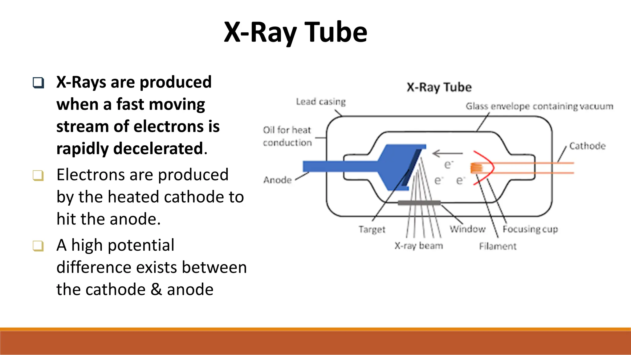
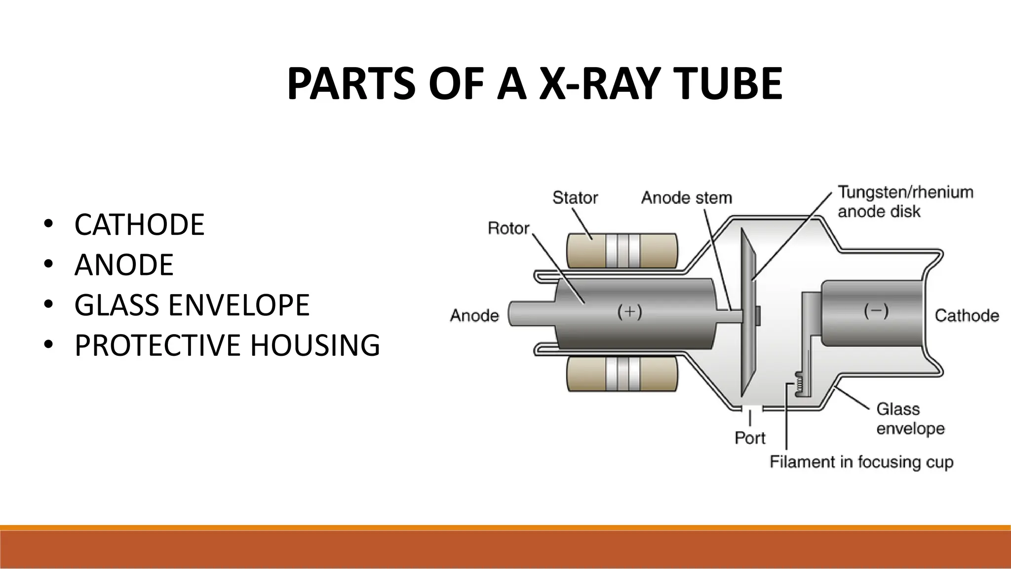
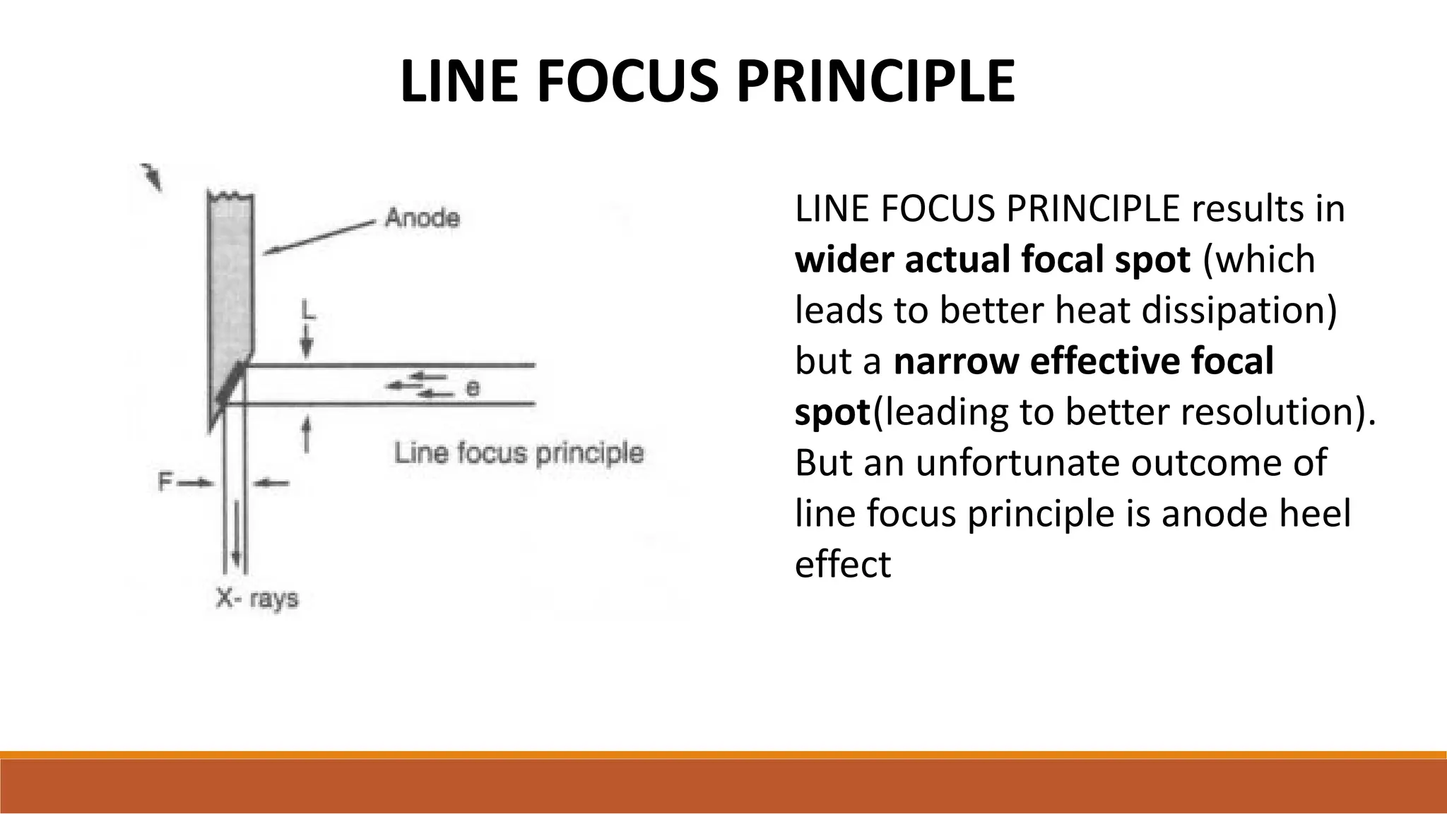
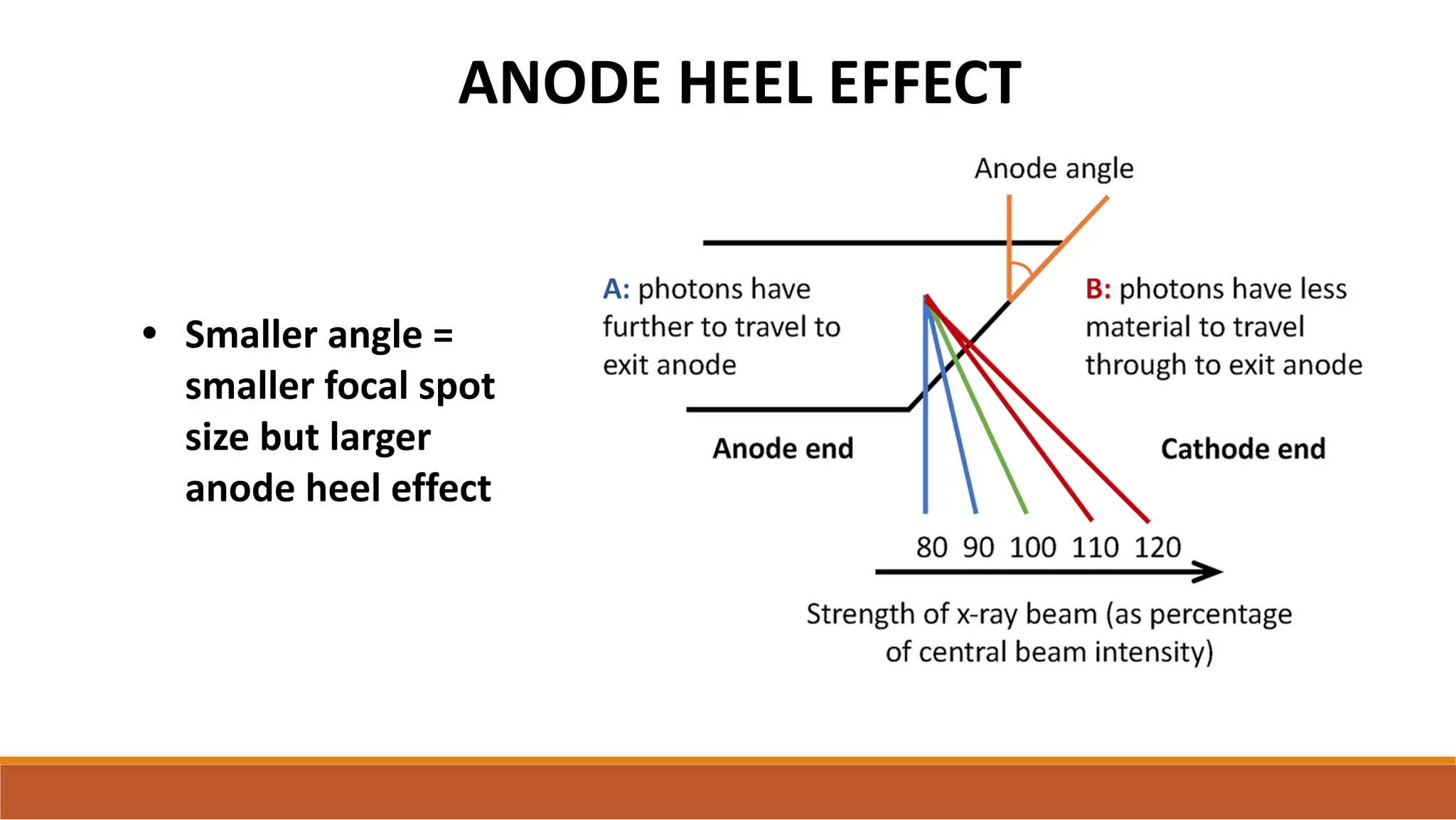
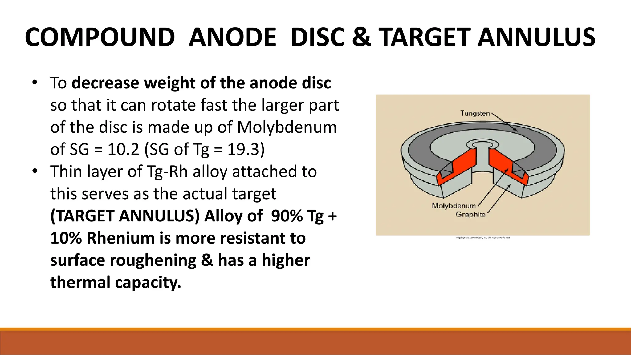
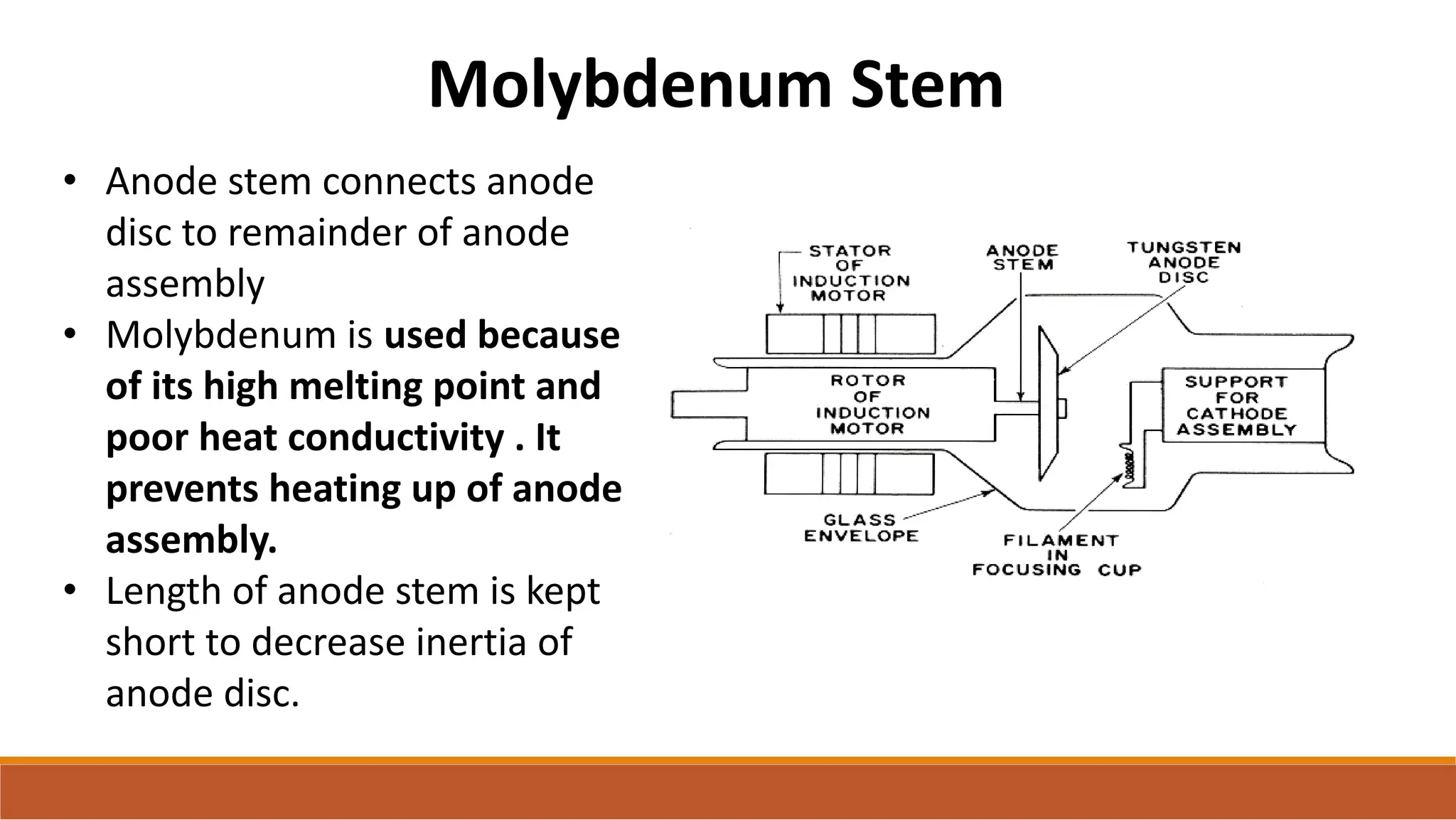
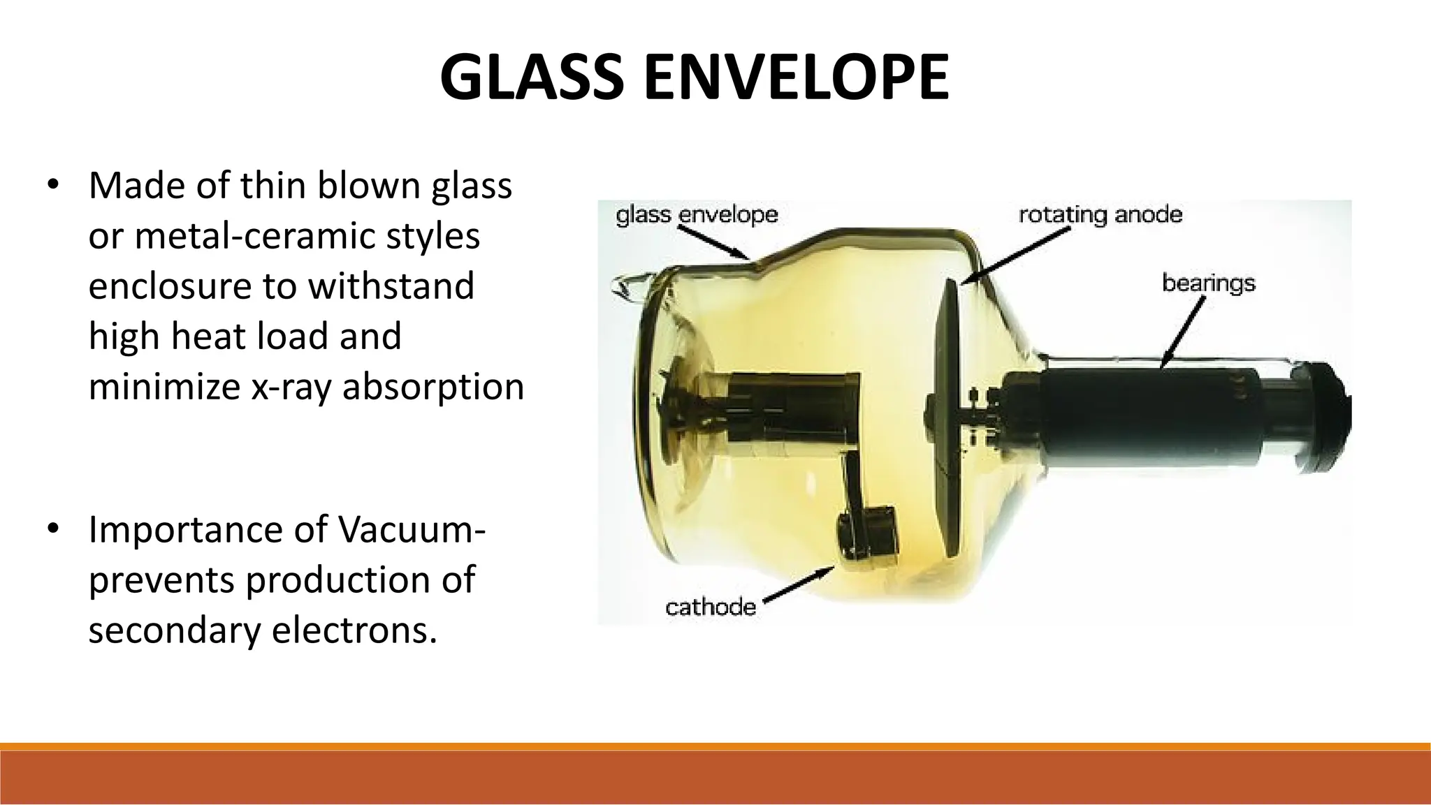
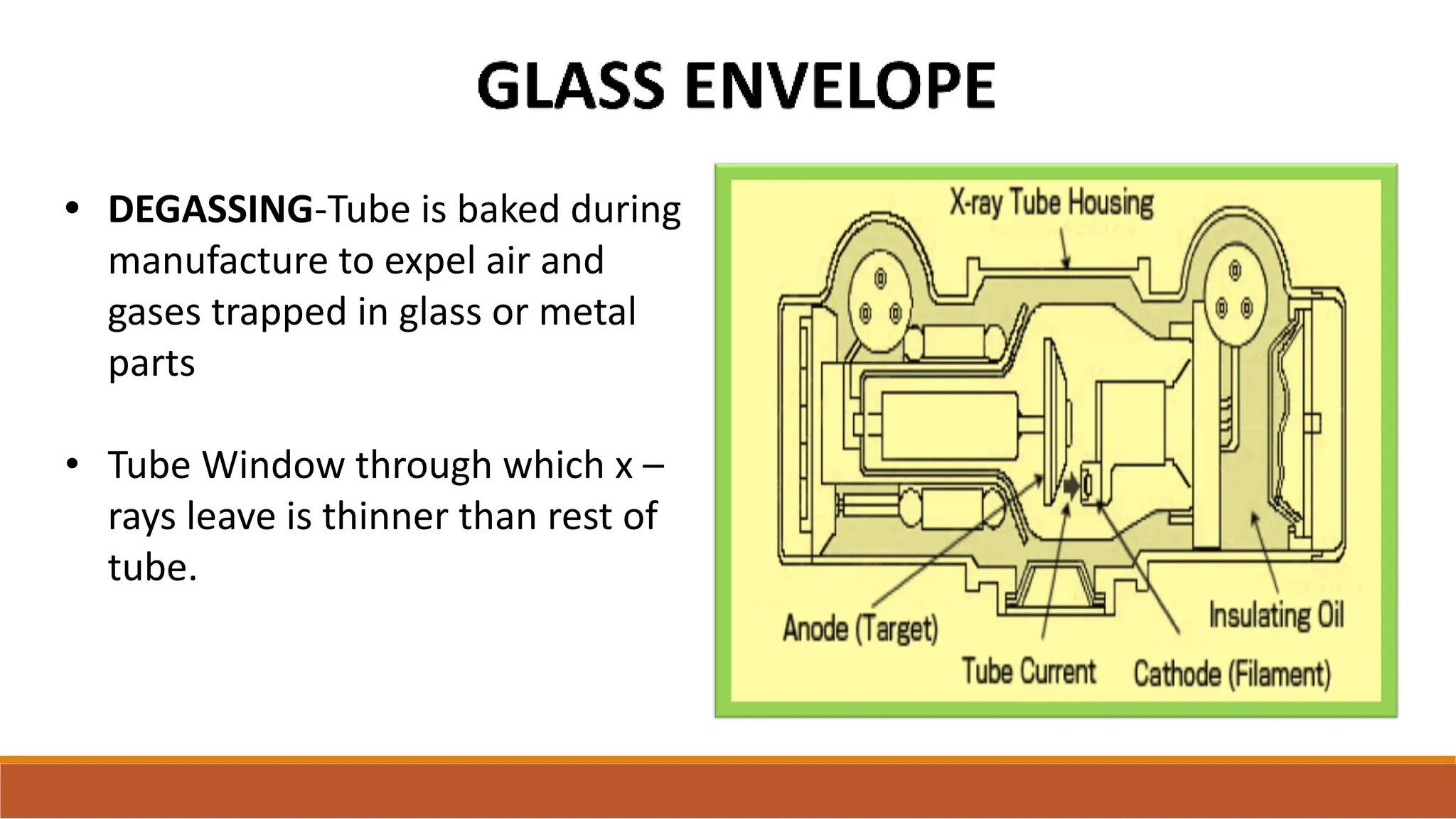
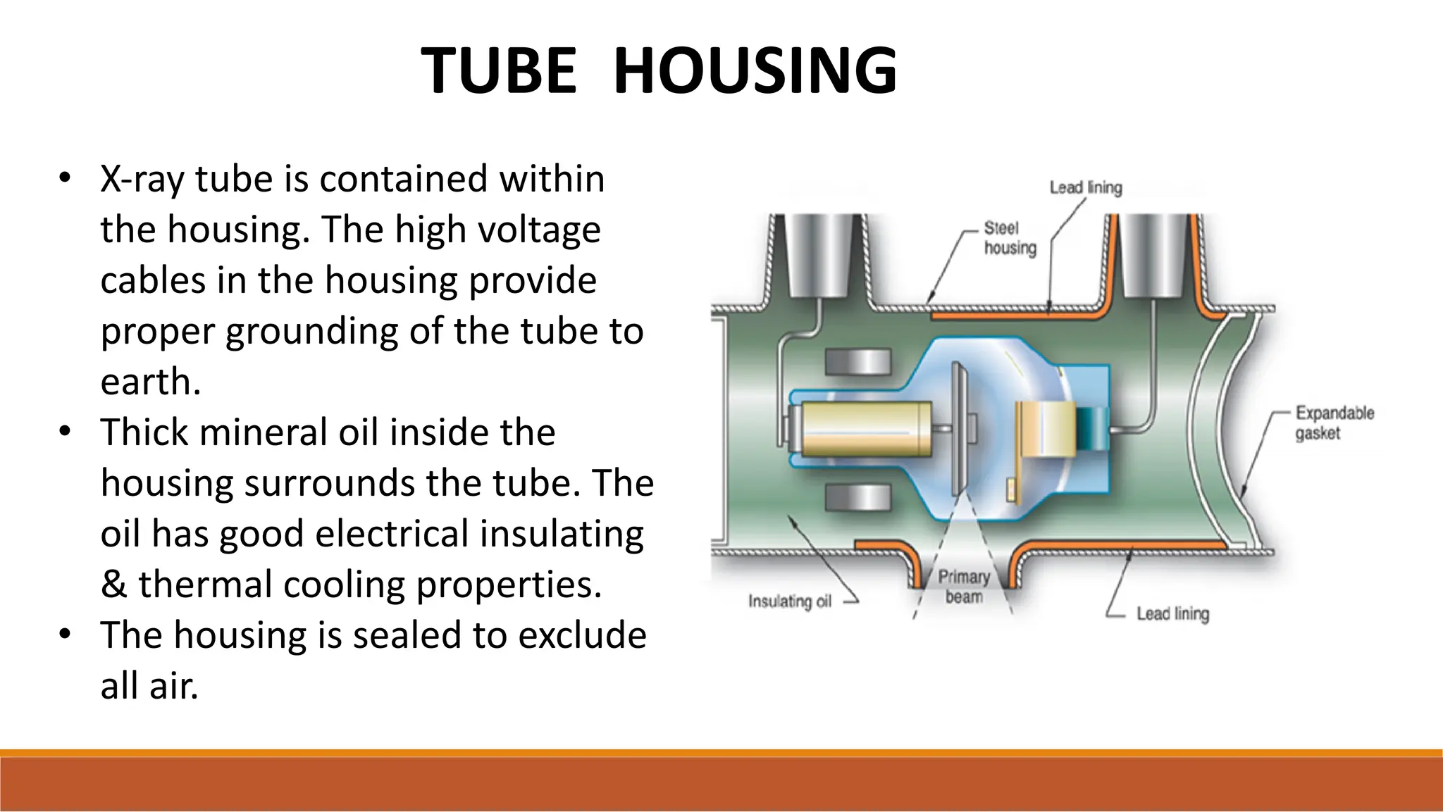
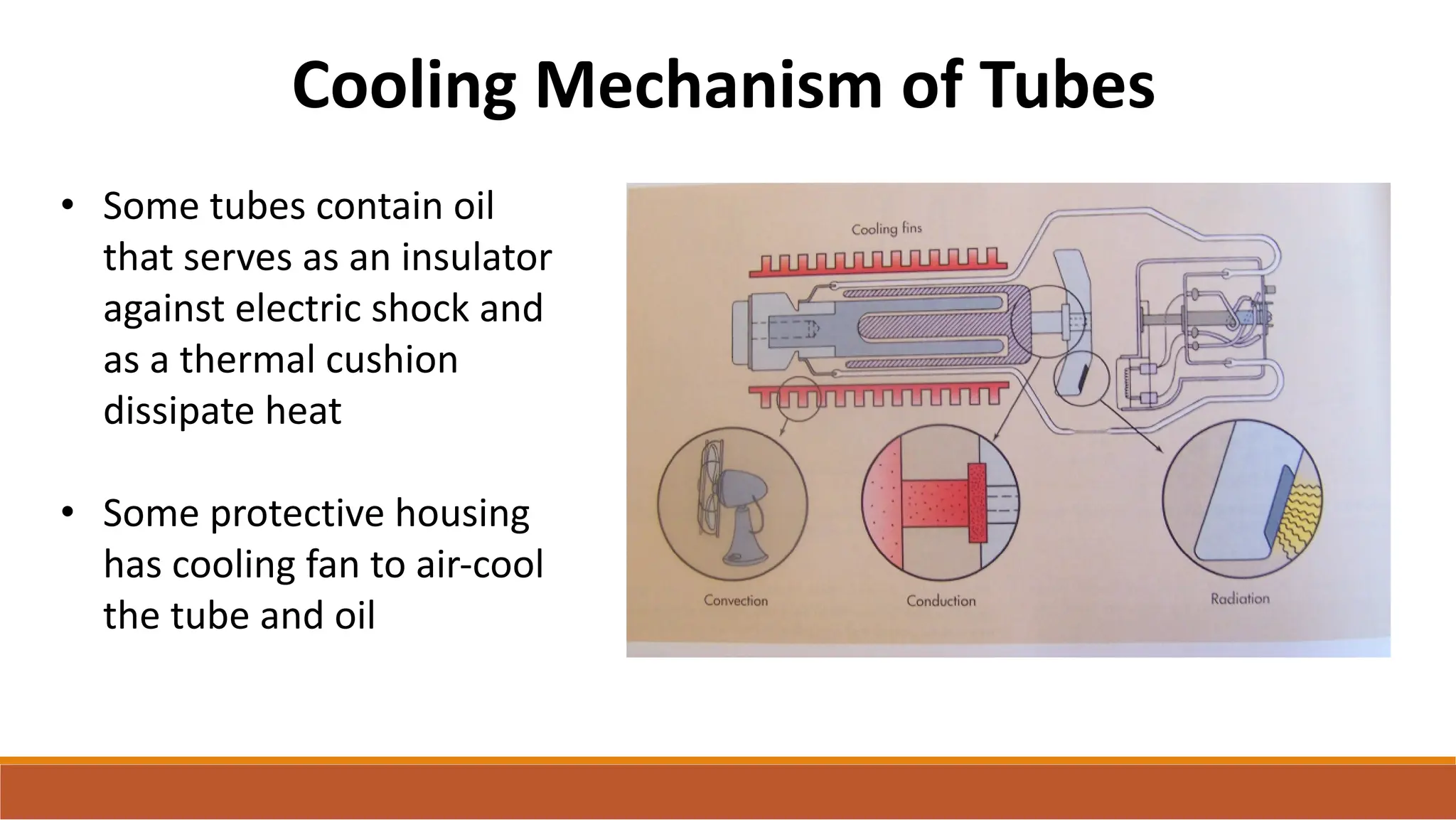
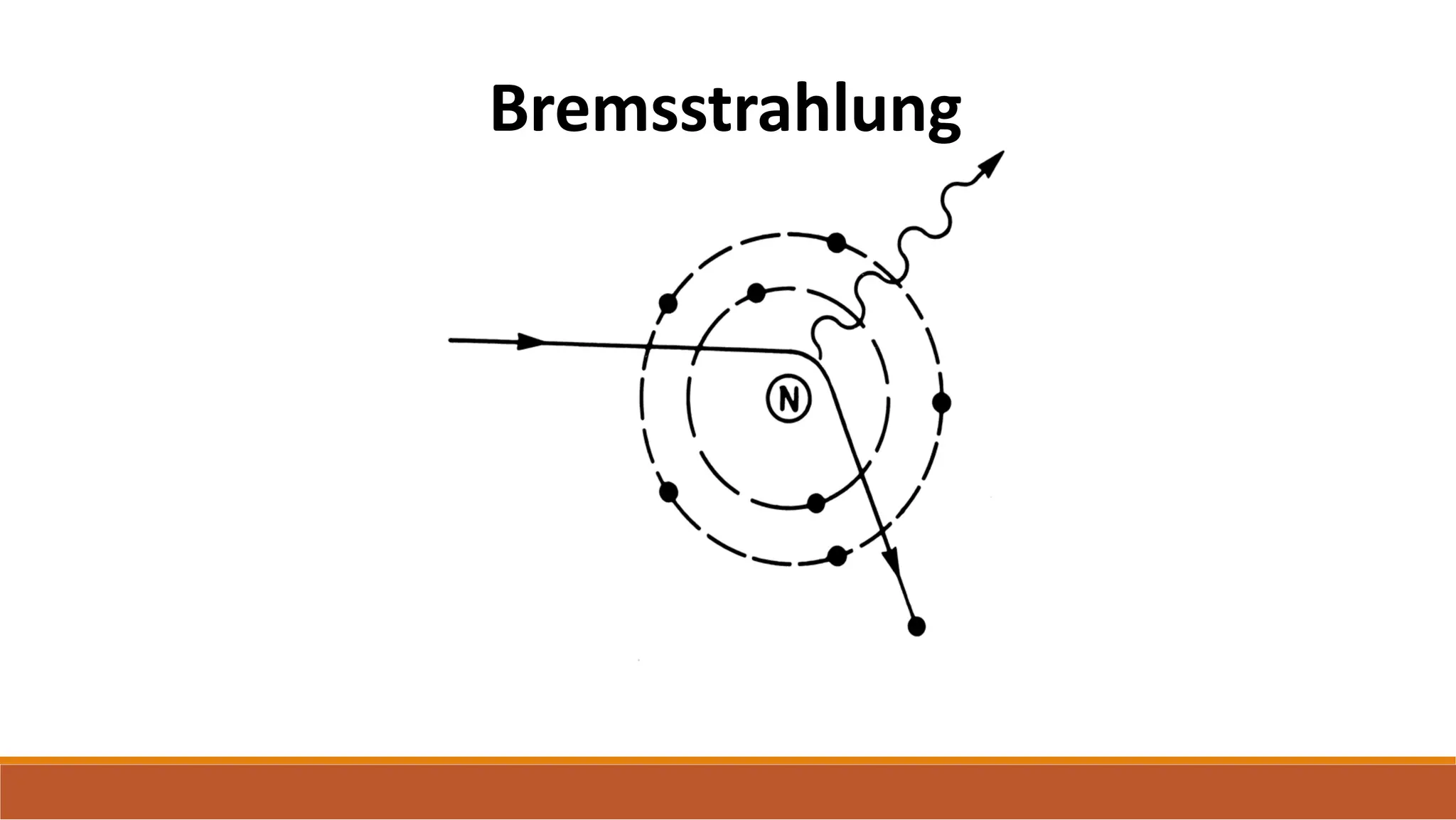
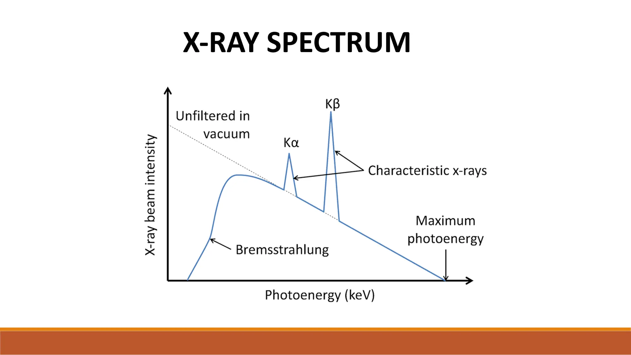
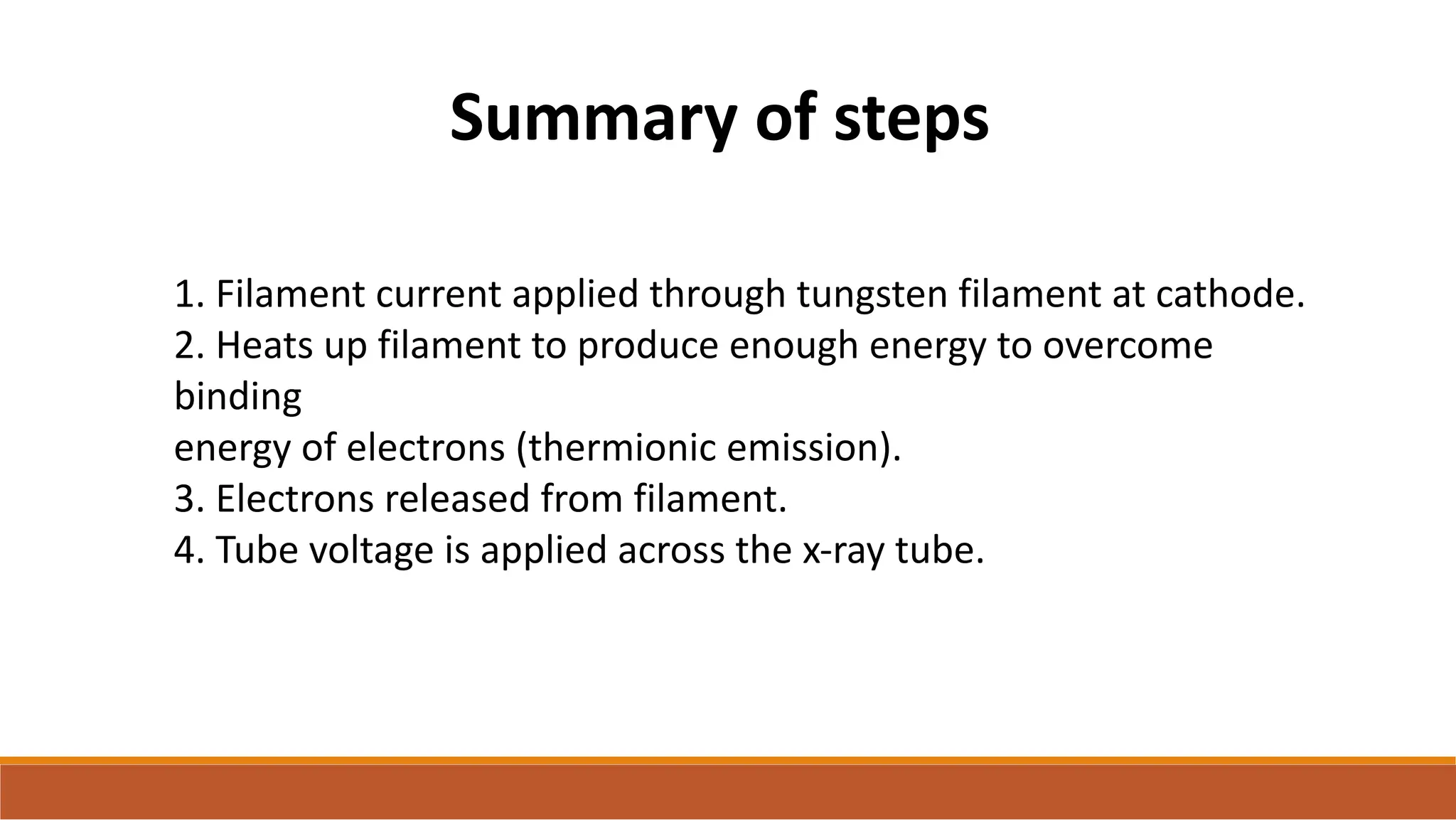
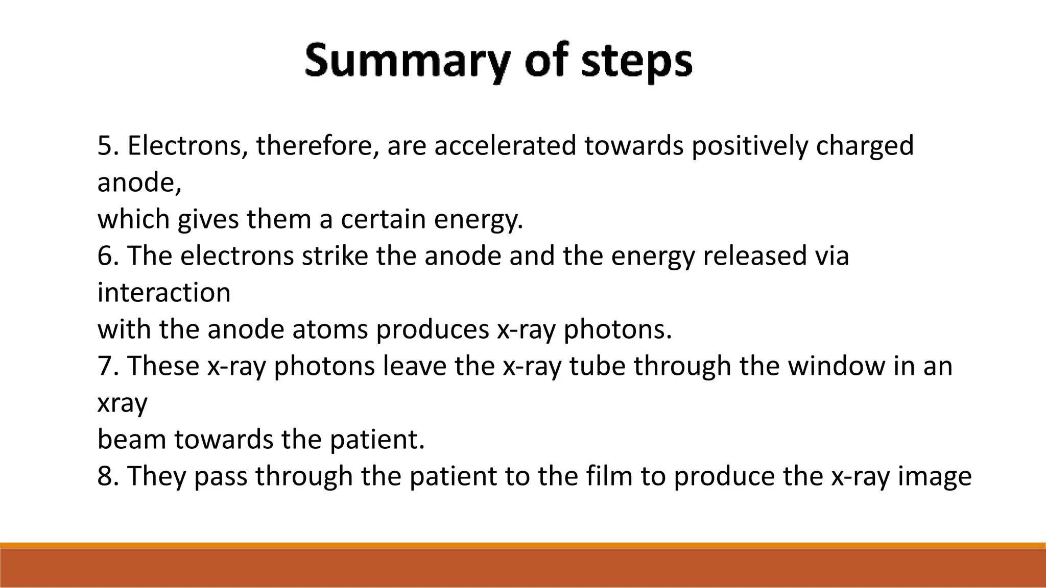
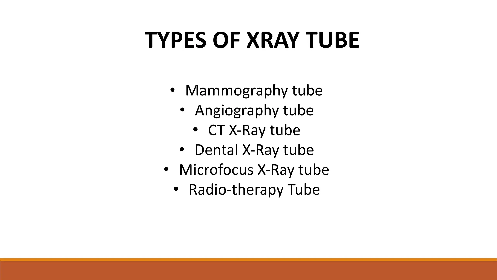
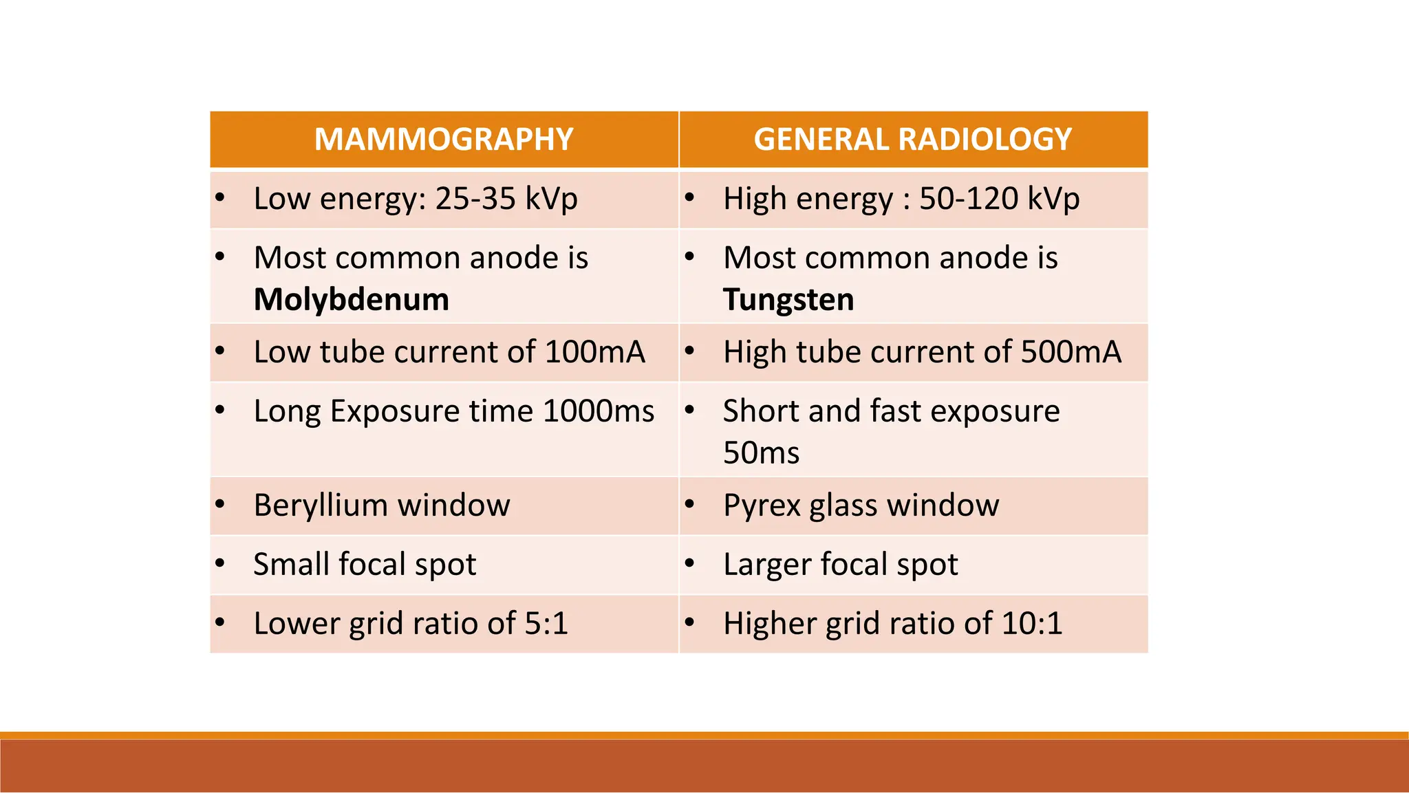
X-RAY PRODUCTION
&
TYPES OF X-RAY TUBES
X-Ray Tube
❑ X-Rays are produced
when a fast moving
stream of electrons is
rapidly decelerated.
❑ Electrons are produced
by the heated cathode to
hit the anode.
❑ A high potential
difference exists between
the cathode & anode
PARTS OF A X-RAY TUBE
• CATHODE
• ANODE
• GLASS ENVELOPE
• PROTECTIVE HOUSING
CATHODE
• Negative terminal of the x-ray tube.
• Consists of –
1.Filament- source of electrons.
2.Connecting wires- supply voltage & amperage to
heat the filament.
3.Metallic focusing cup.
• The quantity of x-rays produced depends on the
NUMBER of electrons that flow from the cathode.
FILAMENT
• Tungsten wire coiled to form a spiral of 0.2mm diameter &
length less than 1 cm.
• Electric current -> heats filament(therm)-> metal atoms
absorb energy ->emit electrons (ions). So the process is
known as Thermionic emission.
• Edison effect- electron cloud surrounding the filament.
• 2200*C – useful no: of electrons.
• The size of the filament relates
to the size of focal spot in the
anode ie small filament=small
focal spot=fine focusing and
large filament=large focal
spot=broad focusing.
Why tungsten??
• It has a high atomic number of 74- so it has a lot of
electrons and can easily release electrons
• It’s a good thermo-ionic emitter
• Can be manufactured as thin wires
• Has a very high melting point of 3422^C
SPACE CHARGE EFFECT
• Electrons formed from the
tungsten form a cloud in
the immediate vicinity of
the filament – Space
charge which inhibits
further release of
electrons – Space charge
effect.
FOCUSING CUP
• Made of molybdenum or
nickel as
a) it has a high melting
point
b) poor thermoionic
emitter so that electrons are
not released.
• Negatively charged to focus
electrons towards the anode
and stop spatial spreading
ANODE
• Positively charged.
• 99% of the kinetic energy of the electrons is converted
to heat and mere 1% is converted to x-rays.
• Thus anode must have a high melting point
• Also for better dissipation of heat the actual focal spot of
the anode is kept as large as possible -Line Focus
Principle.
• There are two types of anode stationary anode and
rotating anode
STATIONARY ANODE
• Small plate of Tg 2-3mm thick embedded in a large mass of
Cu.
• Tungsten - High melting point
- Absorbs & dissipates heat rapidly.
• Cu bonded to the Tg facilitates faster heat dissipation.
• The size of the Tg target is much larger than the actual area of
bombardment. This allows some heat dissipation before it
reaches the Cu which has a lower MP.
• Stationary anodes
are used in dental x-
ray, fluoroscopy and
some portable x-ray
machine
• These are used
where high tube
current and power
are not required.
LINE FOCUS PRINCIPLE
LINE FOCUS PRINCIPLE results in
wider actual focal spot (which
leads to better heat dissipation)
but a narrow effective focal
spot(leading to better resolution).
But an unfortunate outcome of
line focus principle is anode heel
effect
• Smaller angle =
smaller focal spot
size but larger
anode heel effect
ANODE HEEL EFFECT
APPLICATIONS OF ANODE HEEL EFFECT
• The anode should be up and the cathode down for the full
spine x-ray. The patient is less dense at the c-spine and more
dense at the pelvis.
• In mammography the cathode end should be towards the
chest wall while the anode end should be towards the breast
tissue
ROTATING ANODE
• The rotating anode allows the electron beam to interact with a
much larger target area.
• Speed of rotation is 3000rpm.
• To perform the functions of heat dissipation properly anode
assembly is used in rotating anode which basically consists of five
parts:
1)Anode disc 2)Target Annulus
3)Molybdenum Stem 4)Copper Rotor
5)Soft metal lubricated bearings
COMPOUND ANODE DISC & TARGET ANNULUS
• To decrease weight of the anode disc
so that it can rotate fast the larger part
of the disc is made up of Molybdenum
of SG = 10.2 (SG of Tg = 19.3)
• Thin layer of Tg-Rh alloy attached to
this serves as the actual target
(TARGET ANNULUS) Alloy of 90% Tg +
10% Rhenium is more resistant to
surface roughening & has a higher
thermal capacity.
Molybdenum Stem
• Anode stem connects anode
disc to remainder of anode
assembly
• Molybdenum is used because
of its high melting point and
poor heat conductivity . It
prevents heating up of anode
assembly.
• Length of anode stem is kept
short to decrease inertia of
anode disc.
COPPER ROTOR
• Magnetic field produced by the coils induce a current in the Cu rotor
of the induction motor within the envelope. This rotates the anode
disc connected to it.
• Friction b/w the bearings is decreased by using metallic lubricants like
Ag.
To attain high speed of rotation:
• Length of molybdenum stem should be short (less inertia).
• Anode assembly with 2 set of bearings placed wide apart.
• Decrease weight of anode.
GLASS ENVELOPE
• Made of thin blown glass
or metal-ceramic styles
enclosure to withstand
high heat load and
minimize x-ray absorption
• Importance of Vacuum-
prevents production of
secondary electrons.
• DEGASSING-Tube is baked during
manufacture to expel air and
gases trapped in glass or metal
parts
• Tube Window through which x –
rays leave is thinner than rest of
tube.
• Tungsten, vaporized from the filament is deposited as a thin
coating on the inner surface of the glass tube – Bronze
discoloration.
• Tungsten coat on surface of tube - 1. Filters the x ray beam-
changing its quality.
2.Arcing b/w the glass and the electrodes, which at
high voltages can puncture the glass tube.
DISADVANTAGE OF GLASS ENVELOPE
TUBE HOUSING
• X-ray tube is contained within
the housing. The high voltage
cables in the housing provide
proper grounding of the tube to
earth.
• Thick mineral oil inside the
housing surrounds the tube. The
oil has good electrical insulating
& thermal cooling properties.
• The housing is sealed to exclude
all air.
TUBE SHIELDING
• X-rays are emitted with more or less equal intensity in every
direction from the target. Also scattered following collision with
structures in & around the tube.
• High intensity of radiation around the tube results in higher
radiation doses to the patient, personnel & also excessive film
fogging.
• The tube housing is lined with Pb, which absorbs the unwanted
radiations.
EFFECTIVENESS OF SHIELDING
Leakage radiation measured from a distance of 1m from the source
should not exceed 100mR in an hour when the tube is operated at
its maximum continuous rated current for maximum rated tube
potential.
Cooling Mechanism of Tubes
• Some tubes contain oil
that serves as an insulator
against electric shock and
as a thermal cushion
dissipate heat
• Some protective housing
has cooling fan to air-cool
the tube and oil
X-RAY PRODUCTION
It has been dealt in the following sub-headings
• Electron production at cathode
• X-ray production at anode
• X-ray spectrum
Electron production at cathode
• THERMOINIC EMISSION- release of electrons from the cathode.
• ACCELARATING POTENTIAL-Potential difference between cathode and
anode. It is normally 50-150 kV for radiography, 25-40 kV for
mammography and 40-110 kV for fluoroscopy.
• RECTIFICATION – Conversion of ac supply to dc is rectification.
RECTIFICATION
• The conversion of AC current to DC current is known as RECTIFICATION.
• Increased mean photon energy - fewer photons of lower energy
• Increased x-ray output - stays closer to the maximum for longer
• Shorter exposure - as output higher, can run exposure for shorter
time to
get same output
• Lower patient dose - increased mean energy means fewer low
energy
photons that do not contribute to the final image
Effect of rectification on spectrum
X-ray tube current and circuits
• There are 2 types of current flowing in the x-ray tube- a) filament
current b) tube current
• Filament current : usually 10 A
• Tube current : usually 0.5 - 1000 mA.
• To produce two types of current, two types of circuits are used. Low
voltage circuit for filament current and high voltage circuit for tube
current.
LOW VOLTAGE CIRCUIT
• Regulates current flow through
the x-ray tube filament to heat
the filament.
• 3-5A with an applied voltage of
10V.
• To attain this value – step down
transformer.
HIGH VOLTAGE CIRCUIT
• Step-up transformer that
increases the voltage by a
factor of 600.
• Supplies the high PD
across the tube needed
to accelerate the
electrons.
• 2 meters are
incorporated into the
circuit-
• Measure kVp – Voltmeter
• Measure mA - Ammeter
Saturation Voltage
• With increase in kVp , at a constant
filament current, the tube current
increases proportionately upto a
voltage known as saturation
voltage,
• Above this voltage, current is
determined by the number of
electrons made available by heated
filament and is said to be emission
related or temperature related.
X-ray production at anode
At the anode, electrons can interact with the atoms of the anode in
several ways to produce x-ray photons.
1. Outer shell interaction: low energy EM released and quickly
converted
into heat energy
2. Inner shell interaction: produces characteristic radiation
3. Nucleus field interaction: aka Bremsstahlung
For tungsten:
Ek - El (aka Kα) =
59.3 keV
Ek - Em (aka Kβ) =
67.6 keV
Characteristic
radiation
Bremsstrahlung
X-RAY SPECTRUM
FILTERS OF XRAY TUBE
Filters are metal sheets placed in the x-ray beam between the window
and the patient that are used to attenuate the low-energy (soft) x-ray
photons from the spectrum.. If unfiltered these low-energy x-ray
photons are generally absorbed by superficial structures of the body
and contribute to the entrance surface dose (ESD).
INTENSITY OF THE X-RAY BEAM
• No. of photons in x-ray beam × Energy of each
photon.
• Measured in Roentgens/minute.
• Depends on: 1. kVp applied
2. Tube current
3. Target material
4. Filters used
1. Filament current applied through tungsten filament at cathode.
2. Heats up filament to produce enough energy to overcome
binding
energy of electrons (thermionic emission).
3. Electrons released from filament.
4. Tube voltage is applied across the x-ray tube.
Summary of steps
5. Electrons, therefore, are accelerated towards positively charged
anode,
which gives them a certain energy.
6. The electrons strike the anode and the energy released via
interaction
with the anode atoms produces x-ray photons.
7. These x-ray photons leave the x-ray tube through the window in an
xray
beam towards the patient.
8. They pass through the patient to the film to produce the x-ray image
TYPES OF XRAY TUBE
• Mammography tube
• Angiography tube
• CT X-Ray tube
• Dental X-Ray tube
• Microfocus X-Ray tube
• Radio-therapy Tube
MAMMOGRAPHY GENERAL RADIOLOGY
• Low energy: 25-35 kVp • High energy : 50-120 kVp
• Most common anode is
Molybdenum
• Most common anode is
Tungsten
• Low tube current of 100mA • High tube current of 500mA
• Long Exposure time 1000ms • Short and fast exposure
50ms
• Beryllium window • Pyrex glass window
• Small focal spot • Larger focal spot
• Lower grid ratio of 5:1 • Higher grid ratio of 10:1
Angiographic X Ray Tube
• High capacity anode made of rhenium tungsten-
molybdenum with a graphite-backed target for
repeated exposures…
• X-ray tubes with an anode heat capacity of 1300kJ
CT X- Ray Tube
• CT tube is a compact ultra-high cooling X-ray tube
• It uses hydrodynamic bearings in its rotation mechanism.
Hydrodynamic bearings contribute lower vibration, lower noise
• An all-metal (tungsten and molybdenum) high capacity anode.
• Temperature distribution uniformity in all-metal anodes enhances
radiation cooling.
THANK YOU

Study of Xray machines and functions.pdf

  • 1.
  • 2.
    X-Ray Tube ❑ X-Raysare produced when a fast moving stream of electrons is rapidly decelerated. ❑ Electrons are produced by the heated cathode to hit the anode. ❑ A high potential difference exists between the cathode & anode
  • 3.
    PARTS OF AX-RAY TUBE • CATHODE • ANODE • GLASS ENVELOPE • PROTECTIVE HOUSING
  • 4.
    CATHODE • Negative terminalof the x-ray tube. • Consists of – 1.Filament- source of electrons. 2.Connecting wires- supply voltage & amperage to heat the filament. 3.Metallic focusing cup. • The quantity of x-rays produced depends on the NUMBER of electrons that flow from the cathode.
  • 5.
    FILAMENT • Tungsten wirecoiled to form a spiral of 0.2mm diameter & length less than 1 cm. • Electric current -> heats filament(therm)-> metal atoms absorb energy ->emit electrons (ions). So the process is known as Thermionic emission. • Edison effect- electron cloud surrounding the filament. • 2200*C – useful no: of electrons.
  • 6.
    • The sizeof the filament relates to the size of focal spot in the anode ie small filament=small focal spot=fine focusing and large filament=large focal spot=broad focusing.
  • 7.
    Why tungsten?? • Ithas a high atomic number of 74- so it has a lot of electrons and can easily release electrons • It’s a good thermo-ionic emitter • Can be manufactured as thin wires • Has a very high melting point of 3422^C
  • 8.
    SPACE CHARGE EFFECT •Electrons formed from the tungsten form a cloud in the immediate vicinity of the filament – Space charge which inhibits further release of electrons – Space charge effect.
  • 9.
    FOCUSING CUP • Madeof molybdenum or nickel as a) it has a high melting point b) poor thermoionic emitter so that electrons are not released. • Negatively charged to focus electrons towards the anode and stop spatial spreading
  • 10.
    ANODE • Positively charged. •99% of the kinetic energy of the electrons is converted to heat and mere 1% is converted to x-rays. • Thus anode must have a high melting point • Also for better dissipation of heat the actual focal spot of the anode is kept as large as possible -Line Focus Principle. • There are two types of anode stationary anode and rotating anode
  • 11.
    STATIONARY ANODE • Smallplate of Tg 2-3mm thick embedded in a large mass of Cu. • Tungsten - High melting point - Absorbs & dissipates heat rapidly. • Cu bonded to the Tg facilitates faster heat dissipation. • The size of the Tg target is much larger than the actual area of bombardment. This allows some heat dissipation before it reaches the Cu which has a lower MP.
  • 12.
    • Stationary anodes areused in dental x- ray, fluoroscopy and some portable x-ray machine • These are used where high tube current and power are not required.
  • 13.
    LINE FOCUS PRINCIPLE LINEFOCUS PRINCIPLE results in wider actual focal spot (which leads to better heat dissipation) but a narrow effective focal spot(leading to better resolution). But an unfortunate outcome of line focus principle is anode heel effect
  • 14.
    • Smaller angle= smaller focal spot size but larger anode heel effect ANODE HEEL EFFECT
  • 15.
    APPLICATIONS OF ANODEHEEL EFFECT • The anode should be up and the cathode down for the full spine x-ray. The patient is less dense at the c-spine and more dense at the pelvis. • In mammography the cathode end should be towards the chest wall while the anode end should be towards the breast tissue
  • 16.
    ROTATING ANODE • Therotating anode allows the electron beam to interact with a much larger target area. • Speed of rotation is 3000rpm. • To perform the functions of heat dissipation properly anode assembly is used in rotating anode which basically consists of five parts: 1)Anode disc 2)Target Annulus 3)Molybdenum Stem 4)Copper Rotor 5)Soft metal lubricated bearings
  • 17.
    COMPOUND ANODE DISC& TARGET ANNULUS • To decrease weight of the anode disc so that it can rotate fast the larger part of the disc is made up of Molybdenum of SG = 10.2 (SG of Tg = 19.3) • Thin layer of Tg-Rh alloy attached to this serves as the actual target (TARGET ANNULUS) Alloy of 90% Tg + 10% Rhenium is more resistant to surface roughening & has a higher thermal capacity.
  • 18.
    Molybdenum Stem • Anodestem connects anode disc to remainder of anode assembly • Molybdenum is used because of its high melting point and poor heat conductivity . It prevents heating up of anode assembly. • Length of anode stem is kept short to decrease inertia of anode disc.
  • 19.
    COPPER ROTOR • Magneticfield produced by the coils induce a current in the Cu rotor of the induction motor within the envelope. This rotates the anode disc connected to it. • Friction b/w the bearings is decreased by using metallic lubricants like Ag.
  • 20.
    To attain highspeed of rotation: • Length of molybdenum stem should be short (less inertia). • Anode assembly with 2 set of bearings placed wide apart. • Decrease weight of anode.
  • 21.
    GLASS ENVELOPE • Madeof thin blown glass or metal-ceramic styles enclosure to withstand high heat load and minimize x-ray absorption • Importance of Vacuum- prevents production of secondary electrons.
  • 22.
    • DEGASSING-Tube isbaked during manufacture to expel air and gases trapped in glass or metal parts • Tube Window through which x – rays leave is thinner than rest of tube.
  • 23.
    • Tungsten, vaporizedfrom the filament is deposited as a thin coating on the inner surface of the glass tube – Bronze discoloration. • Tungsten coat on surface of tube - 1. Filters the x ray beam- changing its quality. 2.Arcing b/w the glass and the electrodes, which at high voltages can puncture the glass tube. DISADVANTAGE OF GLASS ENVELOPE
  • 24.
    TUBE HOUSING • X-raytube is contained within the housing. The high voltage cables in the housing provide proper grounding of the tube to earth. • Thick mineral oil inside the housing surrounds the tube. The oil has good electrical insulating & thermal cooling properties. • The housing is sealed to exclude all air.
  • 25.
    TUBE SHIELDING • X-raysare emitted with more or less equal intensity in every direction from the target. Also scattered following collision with structures in & around the tube. • High intensity of radiation around the tube results in higher radiation doses to the patient, personnel & also excessive film fogging. • The tube housing is lined with Pb, which absorbs the unwanted radiations.
  • 26.
    EFFECTIVENESS OF SHIELDING Leakageradiation measured from a distance of 1m from the source should not exceed 100mR in an hour when the tube is operated at its maximum continuous rated current for maximum rated tube potential.
  • 27.
    Cooling Mechanism ofTubes • Some tubes contain oil that serves as an insulator against electric shock and as a thermal cushion dissipate heat • Some protective housing has cooling fan to air-cool the tube and oil
  • 28.
    X-RAY PRODUCTION It hasbeen dealt in the following sub-headings • Electron production at cathode • X-ray production at anode • X-ray spectrum
  • 29.
    Electron production atcathode • THERMOINIC EMISSION- release of electrons from the cathode. • ACCELARATING POTENTIAL-Potential difference between cathode and anode. It is normally 50-150 kV for radiography, 25-40 kV for mammography and 40-110 kV for fluoroscopy. • RECTIFICATION – Conversion of ac supply to dc is rectification.
  • 30.
    RECTIFICATION • The conversionof AC current to DC current is known as RECTIFICATION.
  • 31.
    • Increased meanphoton energy - fewer photons of lower energy • Increased x-ray output - stays closer to the maximum for longer • Shorter exposure - as output higher, can run exposure for shorter time to get same output • Lower patient dose - increased mean energy means fewer low energy photons that do not contribute to the final image Effect of rectification on spectrum
  • 32.
    X-ray tube currentand circuits • There are 2 types of current flowing in the x-ray tube- a) filament current b) tube current • Filament current : usually 10 A • Tube current : usually 0.5 - 1000 mA. • To produce two types of current, two types of circuits are used. Low voltage circuit for filament current and high voltage circuit for tube current.
  • 33.
    LOW VOLTAGE CIRCUIT •Regulates current flow through the x-ray tube filament to heat the filament. • 3-5A with an applied voltage of 10V. • To attain this value – step down transformer.
  • 34.
    HIGH VOLTAGE CIRCUIT •Step-up transformer that increases the voltage by a factor of 600. • Supplies the high PD across the tube needed to accelerate the electrons. • 2 meters are incorporated into the circuit- • Measure kVp – Voltmeter • Measure mA - Ammeter
  • 35.
    Saturation Voltage • Withincrease in kVp , at a constant filament current, the tube current increases proportionately upto a voltage known as saturation voltage, • Above this voltage, current is determined by the number of electrons made available by heated filament and is said to be emission related or temperature related.
  • 36.
    X-ray production atanode At the anode, electrons can interact with the atoms of the anode in several ways to produce x-ray photons. 1. Outer shell interaction: low energy EM released and quickly converted into heat energy 2. Inner shell interaction: produces characteristic radiation 3. Nucleus field interaction: aka Bremsstahlung
  • 37.
    For tungsten: Ek -El (aka Kα) = 59.3 keV Ek - Em (aka Kβ) = 67.6 keV Characteristic radiation
  • 38.
  • 39.
  • 40.
    FILTERS OF XRAYTUBE Filters are metal sheets placed in the x-ray beam between the window and the patient that are used to attenuate the low-energy (soft) x-ray photons from the spectrum.. If unfiltered these low-energy x-ray photons are generally absorbed by superficial structures of the body and contribute to the entrance surface dose (ESD).
  • 41.
    INTENSITY OF THEX-RAY BEAM • No. of photons in x-ray beam × Energy of each photon. • Measured in Roentgens/minute. • Depends on: 1. kVp applied 2. Tube current 3. Target material 4. Filters used
  • 42.
    1. Filament currentapplied through tungsten filament at cathode. 2. Heats up filament to produce enough energy to overcome binding energy of electrons (thermionic emission). 3. Electrons released from filament. 4. Tube voltage is applied across the x-ray tube. Summary of steps
  • 43.
    5. Electrons, therefore,are accelerated towards positively charged anode, which gives them a certain energy. 6. The electrons strike the anode and the energy released via interaction with the anode atoms produces x-ray photons. 7. These x-ray photons leave the x-ray tube through the window in an xray beam towards the patient. 8. They pass through the patient to the film to produce the x-ray image
  • 44.
    TYPES OF XRAYTUBE • Mammography tube • Angiography tube • CT X-Ray tube • Dental X-Ray tube • Microfocus X-Ray tube • Radio-therapy Tube
  • 45.
    MAMMOGRAPHY GENERAL RADIOLOGY •Low energy: 25-35 kVp • High energy : 50-120 kVp • Most common anode is Molybdenum • Most common anode is Tungsten • Low tube current of 100mA • High tube current of 500mA • Long Exposure time 1000ms • Short and fast exposure 50ms • Beryllium window • Pyrex glass window • Small focal spot • Larger focal spot • Lower grid ratio of 5:1 • Higher grid ratio of 10:1
  • 46.
    Angiographic X RayTube • High capacity anode made of rhenium tungsten- molybdenum with a graphite-backed target for repeated exposures… • X-ray tubes with an anode heat capacity of 1300kJ
  • 47.
    CT X- RayTube • CT tube is a compact ultra-high cooling X-ray tube • It uses hydrodynamic bearings in its rotation mechanism. Hydrodynamic bearings contribute lower vibration, lower noise • An all-metal (tungsten and molybdenum) high capacity anode. • Temperature distribution uniformity in all-metal anodes enhances radiation cooling.
  • 48.