
Recommended
More Related Content
What's hot
What's hot (20)
Similar to Faults in xray tube by Sandesh magar
Similar to Faults in xray tube by Sandesh magar (20)
Recently uploaded
Recently uploaded (20)
Faults in xray tube by Sandesh magar
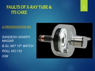
- 1. FAULTS OF X-RAY TUBE & ITS CARE A PRESENTATION BY: SANDESH GHARTI MAGAR B.Sc. MIT 12th BATCH ROLL NO:132 IOM 1
- 2. Introduction X-ray tubes are a proven, cost effective way to produce X radiation useful in medical imaging , inspections & scientific fields. For over 100 years , X-ray tubes have made advances owing to new applications , materials , processing equipment and design. Today two types of tubes are dominating i.e. Stationary anode tube & Rotating anode tube. 2
- 3. In X-ray production, less than 1% of the energy is used to produce x-ray while the remaining 99% is transformed into heat. This factor limits the useful life of the x-ray tube. 3
- 4. GROSS ASPECT With use, X-ray tubes are found to undergo changes which can be linked to a process of ageing & they may also develop a fault as a result of misuse which is mechanical or electrical. Many scientific disciplines are required & must be controlled to produce a quality image & to make the tube life longer. These includes: 4
- 5. 1.Thermodynamics 2.Material science 3.Heat transfer 4.Vacuum technology 5.High voltage 6.Electronics accessories 7.Atomic/Radiation disciplines 8.Manufacturing processes & many other technologies 5
- 6. The deteriorating processes & the fault can be develop due to following reasons: Normal ageing. Deficiencies in Manufacturing. Application Mismatch. Improper Drive by the power supply 6
- 7. 7 Normal Ageing X-ray tubes have a limited life because the characteristics & material used begin a gradual degradation & are consumed so that performance gradually decreases. Ageing in tube can be raised due to faults developed in any part of the x-ray tube as mentioned below:
- 8. Most tubes are manufactured with glass as the vacuum wall vessel but the glass also perform the task of insulating the tube electrode(cathode, anode and ground) from leakage current and arc over. 8Faults in glass envelope
- 9. With time and depending on used exposure factors, tungsten metal from anode and filament begins to evaporate on to the glass surfaces causing eventual arc over and tube failure and reduction in the insulating property 9
- 10. Precautions: Various methods are used to mitigate the effects of the evaporation such as : Sand blasting the glass(which increases the insulating path) Using a hooded anode on stationary anode(a hood reduces target evaporation on to the glass) Metal centered vacuum walls(which reduces filament evaporation on to the glass in rotating anode) Use of ceramics. 10
- 11. NOTE: These techniques do not eliminate metal evaporation but greatly reduces its deposition and at the same time, these techniques can produce other undesirable effects. For e.g. : sand blasting glass can lead to glass particle release which causes arc over. 11
- 12. Faults in anode Due to excessive heating of target, the original smooth surface of target track takes an appearance of paved pathway known as crazy paving. The roughening will reduces the radiation output and will affect sharpness of outline in radiographic imaging. Due to this it may become necessary to increase the exposure value above the normal. As a result, heavy radiographic exposure made on a cold target can cause the anode disc to split radially. The wide cracking can cause imbalance of the anode and increase noise from ball bearing. 12
- 13. An overheated anode disc results in the change in anode angle making the smallest FOV for large sized film. This may also cause greater geometric blur in parts of images. Precautions: Micro cracking in anode disc can be reduced by using: Lowest necessary power. Largest possible focal spot. Longer exposure at reduced power rather than shorter exposure at higher power. 13
- 14. Faults in rotor and its bearing Rotating anode tube consists of rotor which is constructed from more than one metal i.e.; anode stem of Mo & rotor’s body of Cu. Since the rotor and stem becomes hot, the thermal expansion coefficient of these two metals are important and different between them can leads to mechanical changes after much use. High temperature and high speed will reduce bearing life the most. 14
- 15. With operation, the lubricant (which is usually silver or lead metal) wear off of the ball and race surfaces leaving steel to steel contact which leads to binding or jamming. 15
- 16. Precautions: Deteriorating process in bearing can be reduced by: Maintaining normal speed of rotation. Avoiding exposure on cold cathode. Lowering the heat subjection to bearing. Using effective lubricating materials 16
- 17. Faults in the stator windings If the faults develop in the stator windings, there is no power supply to make the anode rotate. As the anode remains stationary due to no power supply, the load that should have been applied to the rotating anode will unknowingly be applied to a stationary one. This is very likely to overload & overheat the anode & can result in cracking of anode disc. The tube can be protected against this type of accident by arranging the circuit which prevent the exposure from taking place when the stator is without its power supply. 17
- 18. Faults in the filament Failure of the filament to heat when its circuit is energized may be due to: i. Break in the filament itself. ii. Faults in the circuit which supplies to power it. Since the filament is heated for every exposure & the heat vaporize the tungsten from it, the filament becomes older & thinner nearly to break which seems like fracture of filament. 18
- 19. Fig: Flowchart of filament Failure 19 No development of images on the film No production of x-rays No reading on mA meter No thermionic emission Failure of the filament to heat
- 20. Precautions: Filament life can be extended, during the use of the tube if the filament is energized only for the shortest periods. 20
- 21. Faults in the vacuum With long use, the x-ray tube may become gassy due to which the vacuum is spoilt. As a result, the milliamperes becomes erratic & runs away so that it reaches the high values.. A gassy tube will go from bad to worse if it continues to be used & the best course of action is to stop using until the tube replacement can be obtained. 21
- 22. Deficiencies in Manufacturing 1. Immediatefailure No matter how hard a manufacturers tries, not all tubes are made exactly same. Small difference exist, but the manufacturer needs to make sure that such differences don’t impact the tube operations. Immediate failure consists of: 22
- 23. i) Weed out by Test: After a tube is produced & processed, it is subjected to different testing's as mentioned below: - Battery test(to make sure it meets the performance standard established for that model). - High voltage stability test(to removes gases & particles. - And others pertinent characteristics are tested & measured. 23
- 24. - Cathode emission test. - Filament volt ampere characteristics - Focal spot size test. - Thermal loading. - Noise, vibration( for rotor & stator) Tubes that don’t meets the specifications are rejected & analyzed. So that corrections can be made immediately 24
- 25. ii)Hold Period: Sometimes, despite the satisfactory testing if tubes are held for 2-4 weeks, they don’t perform satisfactorily esp. under high voltage conditions. The change in performance is usually caused by tiny vacuum leaks which don’t allow high voltage performance. Such degradation of performance is rare but can be improved immediately. 25
- 26. iii)Improper Materials: Modern materials like: - Oxygen free copper, - Controlled expansion cobalt alloys, - Rhenium fused Tungsten, - High hot strength alloys, - Vacuum grade graphite, - High temperature grade, - Ceramics & technical glasses, have vastly improved tube performance. 26
- 27. Despite these efforts, a high level of quality assurance is necessary to guarantee these material quality. Otherwise, due to improper materials, x-ray tube can felt defects & faults. 27
- 28. iv)Process failure: New processes such as: - Vacuum re-melted metals, - Turbo-molecular vacuum pumps, - High temperature hydrogen gas firing, -High temperature vacuum processing, have improved x-ray tube performance. Automation has helped to insure more consistent product. However if these processes/equipment utilized become faulty or the control is lost, a well-tuned process can easily fail & marginal or reject tubes can result. 28
- 29. 2. Latent failure Latent or unpredictable failures which occurs in time are often unforeseen & sometimes may not be attributable to a known cause. Latent failure consists of: 29
- 30. i)Process optimization: Many process are used on tubes and their parts have evolved over many years & through practical experiences. Such as: - Outgassing, - Vacuum pumping, - Seasoning. Unless there is very clear contrary evidence, manufacturers are reluctant to change a process for the fear of unknown consequences. So it is difficult to find a suitable compromise & once a process works it is often best to leave it alone. 30
- 31. ii)Marginal or Poorly understood processes: Some failures are caused by effects that are not well known. Such as: - Why does dielectric oil sometimes become dark & have foreign materials, yet the tube operate ok? - While the other system exhibit arcing, yet why the tube & cooling oil and surrounding look & test ok? 31
- 32. Application mismatch In early mammography, a standard diagnostic tube was used to produce mammograms So the resulting diagnosis was poor & radiation burns often resulted. Over several years, it was learned that molybdenum radiation, at voltage of about 25-30 kvp with very small focal spot is best to produce the quality image of breast on mammograms. Application mismatch can be described as below: 32
- 33. i) Low kv/High mA emission: A common mismatch can occur when a tube designed for high voltage use is used at lower voltages. Due to this reason, the filament has to be run at high emission current to overcome the limited emission. In a particular rotating anode tube, operated at 125 kvp & 300 mA when decreased to 50 kvp & 300 mA, the filament must be operated at 16% more power to overcome the lower tube voltage which can shortens the tube life. 33
- 34. ii)Temperature: A basic rule for x-ray tubes is that temperature is always consider as the biggest enemy. The more power applied, the shorter the tube life. However without adequate power, there may not be enough x-radiation intensity to get the job done. Filament evaporation causing unwanted metallic deposition will eventually lead to insulator arc over. 34
- 35. Improper drive by the power supply In an x-ray source, the power supply provides all the necessary power to operate the tube including the filament, rotor, stator, accelerations, Thus, the power supply is an integral part of the x-ray tube. Power supply can be described as below: 35
- 36. i)Supply Impedance: Most critical characteristic of the power supply is its impedance. For stationary anode tube with high impedance, means that it contains a lot of resistance. So, in case of damage to tube and sensitive electronics, damage is minimized by maintaning good control of voltage through impedance. A rotating anode tube operates under much high power condition, sometimes over 100 KW or almost 1000 times a stationary anode. Here, the supply cannot have high impedance other wise it would not support the required power. 36
- 37. ii)High frequency: The glass-to-metal seals in a tube are made from kovar or similar alloy consisting of iron, nickel & cobalt alloy of which are highly magnetic. Under high frequency, the magnetic materials are subjected to magnetic hysteresis loss, eddy currents loss & the skin effect which sap the energy from the current flow. Currently, frequencies of up to 40 kHz are employed. For the cathode & anode, high frequency, high voltage supplies are employed, but these are rectified to DC. 37
- 38. iv)Rotation speed: For rotating tubes, bearing life as well as filament evaporation is a major consideration for tube life. Power supply to the rotor & stator determines the rotation speed. So, the power supply should be maintained very wisely. 38
- 39. v)Filament Boost: A current limiting or controlling device is place in series between the constant current source & filament. The amount of current controls the temperature of filament. One of the problem with a constant current source, is that it brings the filament up to the selected operating temperature gradually. 39
- 40. To bring the filament up to temperature more quickly , a current boost is applied when the current to the filament is 1st turned on. That is , instead of supplying the normal operating current to the filament, a higher current is provided for a pre selected short duration. 40
- 41. Fig: Chart ShowingFilament Boosting 41
- 42. Care of the X-ray Tube 42
- 43. Introduction With proper care, the life of the tube can be extended with normal use. The following precautions should be applied for safe use of x ray tube and its care: MINIMIZE THE FILAMENT BOOST TIME Current applied for too long will shorten filament life and will lead to unstable operation. 43
- 44. WARM UP THE ANODE FOLLOWING THE MANUFACTURER’S RECOMMENDATION In order to prevent tube from the thermal shock, preheat the tube anode by performing the following procedure. This procedure should be performed if the system has not been energized for 2 hours or longer. 44
- 45. USE LOW TUBE CURRENT The high filament current required to produce high tube current(mA) will cause evaporation of the tungsten from the filament and then , it will be deposited on to the glass envelope. 45
- 46. LIMIT OPERATION TO 80%OF MAXIMUM SINGLE EXPOSURE RATING Although higher power levels are both possible and permitted this reduction will help assure long focal track life. Also, it will minimize the reduction in radiation output associated with a roughened focal track. 46
- 47. DO NOT ROTATE THE TUBE HOUSING RAPIDLY FROM ONE POSITION TO ANOTHER Sudden movement will produce tension or pressure to the x-ray tube. The gyroscopic effect may crack or otherwise damage the rotor. 47
- 48. FOLLOWRating Charts Failure of the x ray tube can be prevented with the use of tube rating chart. It is essential that radiologic technologist be able to understand and read these charts even though many of these charts are now digitally stored. There are 3 types of rating charts: The radiographic rating chart The anode cooling chart The housing cooling chart 48
- 49. RADIOGRAPHIC RATING CHART The radiographic rating chart is most important because it conveys which radiographic techniques are safe and which techniques are unsafe for x-ray tube operation. The x axis and y axis shows scales of the two radiographic parameter-time and kVp. For a given mA ,any combination of kVp and time that lies below the mA curve is safe and above is unsafe 49
- 50. If an unsafe exposure was made ,the tube might fail abruptly but a x ray imaging system have a built in safety features that would not allow an exposure to be made. There are different chart for each filament (large or small focal spot) ,the speed of anode rotation (3400rpm or 10,000rpm) , the target angle , and the voltage rectification. An appropriate radiographic rating chart is supplied with each replacement of x ray tube and can be different from that of original tube. 50
- 52. THE ANODE COOLING CHART The thermal capacity of an anode and its heat dissipation characteristics are contained in a rating chart known as anode cooling rating chart. Unlike the radiographic rating chart , the anode cooling chart does not depend on the size of filament or the rotation speed. The rate of cooling is rapid at first and gradually slows as the anode cools. In addition to determining the maximum heat capacity of the anode , it is used to determine the time required for complete cooling after any level of heat input. 52
- 53. Fig: Anode Cooling Chart 53
- 54. HOUSING COOLING CHART Ability of entire tube housing to withstand heat is represented by housing cooling rating chart which has chart similar to anode rating chart and used in same way. X ray tube housing generally have a maximum heat capacity lies in the range of 1 to 1.5 million HU. Complete cooling of tube housing after maximum heat capacity requires for 1 to 2 hours. About twice the amount of time is required without fan powered air circulation. 54
- 55. Fig: House cooling chart 55
- 56. Summary: • Tube fault can occur in any part of the tube like glass envelope , anode , filament, rotor , stator winding , vacuum etc. • Excessive heat results in reduced x ray tube life. • Maximum radiographic techniques should never be applied to a cold anode. • Tube rating charts printed by manufacturers of x ray tubes aid the radiologic technologists in using acceptable exposure levels to maximize the x ray tube life. 56
- 57. REFERENCE: Radiologic science for technologist by STEWART CARLYLE BUSHONG the essential physics of medical imaging by JERROLD T. BUSHBERG Chesney’s equipment for students radiographers by P.H. CARTER 57
- 58. 58 Thank you
Editor's Notes
- FFD
- Microprocessor control=does not allow an unsafe exposure
- HU=KVP*MA*TIME 1HU=1.4J HU for single phase=0.7J HU for 3 phase or high frequency=1J