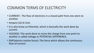
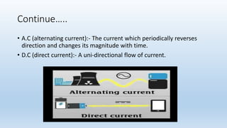
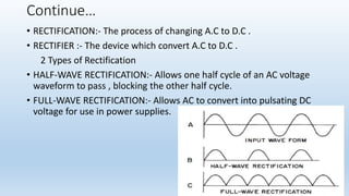
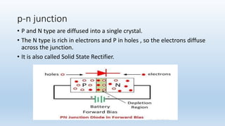
GENERATORS
AND
ITS TYPES
DEEPAK NEGI
MRIT
TMU
INDEX
• INTRODUCTION
• COMMON TERMS OF ELECTRICITY
(CURRENT , VOLTAGE , E.M.F , A.C , D.C , RECTIFIER , p.n junction)
• GENERATOR
• WORKING OF GENERATOR
• XRAY GENERATOR
• 3 PULSE
• 6 PULSE, 6 RECTIFIER
• 12 PULSE
• RIPPLE FACTOR
• ADVANTAGE AND APPLICATIONS
GENERATOR
• A device which converts mechanical energy into electricity.
• First discovered in 1831, by MICHAEL FARADAY .
• A BRITISH SCIENTIST.
• They use to work on electrostatic principle.
COMMON TERMS OF ELECTRICITY
• CURRENT:- The flow of electrons in a closed path from one atom to
another.
• Ampere (A)-SI Unit.
• It is also know as Potential, which is basically the work done by
current.
• VOLTAGE:-The work done to move the charge from one point to
another is called voltage or POTENTIAL DIFFERENCE.
• EMF(electro motive force):-The force which allows the continuous
flow of current.
Continue…..
• A.C (alternating current):- The current which periodically reverses
direction and changes its magnitude with time.
• D.C (direct current):- A uni-directional flow of current.
Continue…
• RECTIFICATION:- The process of changing A.C to D.C .
• RECTIFIER :- The device which convert A.C to D.C .
2 Types of Rectification
• HALF-WAVE RECTIFICATION:- Allows one half cycle of an AC voltage
waveform to pass , blocking the other half cycle.
• FULL-WAVE RECTIFICATION:- Allows AC to convert into pulsating DC
voltage for use in power supplies.
p-n junction
• P and N type are diffused into a single crystal.
• The N type is rich in electrons and P in holes , so the electrons diffuse
across the junction.
• It is also called Solid State Rectifier.
Continue….
• DIODE:- A two terminal electronic component that conducts current
primarily in one direction.
• Has low resistance in one direction , and high on the other.
GENERATOR
• A device which converts mechanical energy into electric energy.
Working of Generator
• According to Faraday’s law of electromagnetic induction, when a
conductor links with a changing flux, it will have an induced emf
across it. The value of induced emf across the conductor depends on
the rate of change of flux linkage with the conductor.
• The direction of the induced emf in the conductor can be determined
by Fleming’s Right Hand Rule.
Continue
• when we rotate single loop of a conductor in a magnetic field.
• At point A the loop is in rest an no current is induced into it .
• As it rotates and move to about an angle of 90 the maximum lines of
magnetic flux interact with the loop and current is induced in this
point (B).
• Again when it rotates to 180 degree almost no magnetic field lines
interact with the coil and no current is induced . Point (C)
• Now the coil rotates to 270 degree again magnetic flux interacts and
current is induced . Point (D)
• Finally it rotates 360 degree and comes to rest again.
X-RAY GENERATOR
• X-RAY Generator provide electric power to the tube.
• Tube requires electric energy for 3 purpose .
a. To emit electrons from the filament.
b. To accelerate these electrons from the cathode to the anode.
c. A time mechanism , which regulates the length of the xray
exposure.
The mechanism of an xray generator is in 2 separate components.
a. A control panel (console)
b. Transformer assembly.
TRANSFORMER
• Used to alter voltage and current .
• AUTO-TRANSFORMER:- The voltage from the main supply passes through
the auto-transformer, which supplies it further to other components as
per the requirement.
• STEP-DOWN TRANSFORMER:- Heats the filament.
• STEP-UP TRANSFORMER:- Provides potential.
3 PHASE GENERATOR
• In this 3 coils are incorporated at an angle of 120 degree to each
other.
• Coil 1 is moving with the lines of magnetic force and consequently no
e.m.f. is being induced.
• Coil 2 has passed point B at which maximum voltage was induced and
its e.m.f. is reducing towards zero value.
• Coil 3 is approaching the point where the voltage reaches its
maximum.
3 PHASE GENERATOR
SIX PULSE, SIX RECTIFIER
• The three-phase (six-pulse) generator is
connected to three live phases.
Primary transformer employs a delta wound.
• Secondary transformer with a wye wound .
• The output of the secondary winding is
Rectified with a six solid state rectifier.
SIX PULSE , TWELVE RECTIFIER
Uses 2 sets of secondary windings in the wye or star winding .
Consists of 2 six pulse bridge circuits connected in series .
Primary winding uses delta winding.
12 Rectifier works as 6 full wave bridge .
TWELVE PULSE
• A twelve-pulse transformer looks similar to the
six-pulse , twelve-rectifier transformer.
• The difference is that the secondary is not a
Double wye connection.
• it is a wye and a delta connection.
• Delta lags the wye by 30 degree.
RIPPLE FACTOR
• The ripple factor is the variation in the voltage across the x-ray tube
expressed as a percentage of the maximum value.
• Single phase = 100% (voltage goes from 0 to maximum)
• Six pulse =13.5%
• Twelve pulse=3.5%
Advantages of the three-phase over single-
phase circuits
(1) more X-rays,
(2) X-rays of shorter average wavelength than the single phase
unit, even though kVp and mA are the same In each case.
• single-phase voltage is at or near zero point at the beginning and end
of each half cycle, the rectified three-phase voltage is close to peak
value at all times and never drops to zero value.
Radiographic advantages of three-phase X-ray
generators
compared to those operating on single-phase
• As the kV remains constantly at a high value during the exposure
(1) Less soft radiation is produced, resulting in a reduction in skin dose
to the patient.
(2) More X-rays are produced for a given mA .
(3) Because of more xrays the same film dose, e.g. radiographic
exposure, can be achieved in a shorter time. Therefore reduction in
exposure times is achieved.
(4) Improved tube rating is achieved at short exposure time.
(5) The X-ray tube has a longer life due to more even thermal loading.
REFERENCE
• Equipment's in Diagnostic radiology –E.Forster
• Christensen’s physics of diagnostic radiology

X ray generators and its type

  • 1.
  • 2.
    INDEX • INTRODUCTION • COMMONTERMS OF ELECTRICITY (CURRENT , VOLTAGE , E.M.F , A.C , D.C , RECTIFIER , p.n junction) • GENERATOR • WORKING OF GENERATOR • XRAY GENERATOR • 3 PULSE • 6 PULSE, 6 RECTIFIER • 12 PULSE • RIPPLE FACTOR • ADVANTAGE AND APPLICATIONS
  • 3.
    GENERATOR • A devicewhich converts mechanical energy into electricity. • First discovered in 1831, by MICHAEL FARADAY . • A BRITISH SCIENTIST. • They use to work on electrostatic principle.
  • 4.
    COMMON TERMS OFELECTRICITY • CURRENT:- The flow of electrons in a closed path from one atom to another. • Ampere (A)-SI Unit. • It is also know as Potential, which is basically the work done by current. • VOLTAGE:-The work done to move the charge from one point to another is called voltage or POTENTIAL DIFFERENCE. • EMF(electro motive force):-The force which allows the continuous flow of current.
  • 5.
    Continue….. • A.C (alternatingcurrent):- The current which periodically reverses direction and changes its magnitude with time. • D.C (direct current):- A uni-directional flow of current.
  • 6.
    Continue… • RECTIFICATION:- Theprocess of changing A.C to D.C . • RECTIFIER :- The device which convert A.C to D.C . 2 Types of Rectification • HALF-WAVE RECTIFICATION:- Allows one half cycle of an AC voltage waveform to pass , blocking the other half cycle. • FULL-WAVE RECTIFICATION:- Allows AC to convert into pulsating DC voltage for use in power supplies.
  • 7.
    p-n junction • Pand N type are diffused into a single crystal. • The N type is rich in electrons and P in holes , so the electrons diffuse across the junction. • It is also called Solid State Rectifier.
  • 8.
    Continue…. • DIODE:- Atwo terminal electronic component that conducts current primarily in one direction. • Has low resistance in one direction , and high on the other.
  • 9.
    GENERATOR • A devicewhich converts mechanical energy into electric energy.
  • 11.
    Working of Generator •According to Faraday’s law of electromagnetic induction, when a conductor links with a changing flux, it will have an induced emf across it. The value of induced emf across the conductor depends on the rate of change of flux linkage with the conductor. • The direction of the induced emf in the conductor can be determined by Fleming’s Right Hand Rule.
  • 12.
    Continue • when werotate single loop of a conductor in a magnetic field. • At point A the loop is in rest an no current is induced into it . • As it rotates and move to about an angle of 90 the maximum lines of magnetic flux interact with the loop and current is induced in this point (B). • Again when it rotates to 180 degree almost no magnetic field lines interact with the coil and no current is induced . Point (C) • Now the coil rotates to 270 degree again magnetic flux interacts and current is induced . Point (D) • Finally it rotates 360 degree and comes to rest again.
  • 13.
    X-RAY GENERATOR • X-RAYGenerator provide electric power to the tube. • Tube requires electric energy for 3 purpose . a. To emit electrons from the filament. b. To accelerate these electrons from the cathode to the anode. c. A time mechanism , which regulates the length of the xray exposure. The mechanism of an xray generator is in 2 separate components. a. A control panel (console) b. Transformer assembly.
  • 14.
    TRANSFORMER • Used toalter voltage and current .
  • 15.
    • AUTO-TRANSFORMER:- Thevoltage from the main supply passes through the auto-transformer, which supplies it further to other components as per the requirement. • STEP-DOWN TRANSFORMER:- Heats the filament. • STEP-UP TRANSFORMER:- Provides potential.
  • 16.
    3 PHASE GENERATOR •In this 3 coils are incorporated at an angle of 120 degree to each other. • Coil 1 is moving with the lines of magnetic force and consequently no e.m.f. is being induced. • Coil 2 has passed point B at which maximum voltage was induced and its e.m.f. is reducing towards zero value. • Coil 3 is approaching the point where the voltage reaches its maximum.
  • 17.
  • 18.
    SIX PULSE, SIXRECTIFIER • The three-phase (six-pulse) generator is connected to three live phases. Primary transformer employs a delta wound. • Secondary transformer with a wye wound . • The output of the secondary winding is Rectified with a six solid state rectifier.
  • 19.
    SIX PULSE ,TWELVE RECTIFIER Uses 2 sets of secondary windings in the wye or star winding . Consists of 2 six pulse bridge circuits connected in series . Primary winding uses delta winding. 12 Rectifier works as 6 full wave bridge .
  • 20.
    TWELVE PULSE • Atwelve-pulse transformer looks similar to the six-pulse , twelve-rectifier transformer. • The difference is that the secondary is not a Double wye connection. • it is a wye and a delta connection. • Delta lags the wye by 30 degree.
  • 21.
    RIPPLE FACTOR • Theripple factor is the variation in the voltage across the x-ray tube expressed as a percentage of the maximum value. • Single phase = 100% (voltage goes from 0 to maximum) • Six pulse =13.5% • Twelve pulse=3.5%
  • 22.
    Advantages of thethree-phase over single- phase circuits (1) more X-rays, (2) X-rays of shorter average wavelength than the single phase unit, even though kVp and mA are the same In each case. • single-phase voltage is at or near zero point at the beginning and end of each half cycle, the rectified three-phase voltage is close to peak value at all times and never drops to zero value.
  • 23.
    Radiographic advantages ofthree-phase X-ray generators compared to those operating on single-phase • As the kV remains constantly at a high value during the exposure (1) Less soft radiation is produced, resulting in a reduction in skin dose to the patient. (2) More X-rays are produced for a given mA . (3) Because of more xrays the same film dose, e.g. radiographic exposure, can be achieved in a shorter time. Therefore reduction in exposure times is achieved. (4) Improved tube rating is achieved at short exposure time. (5) The X-ray tube has a longer life due to more even thermal loading.
  • 24.
    REFERENCE • Equipment's inDiagnostic radiology –E.Forster • Christensen’s physics of diagnostic radiology