Downloaded 237 times


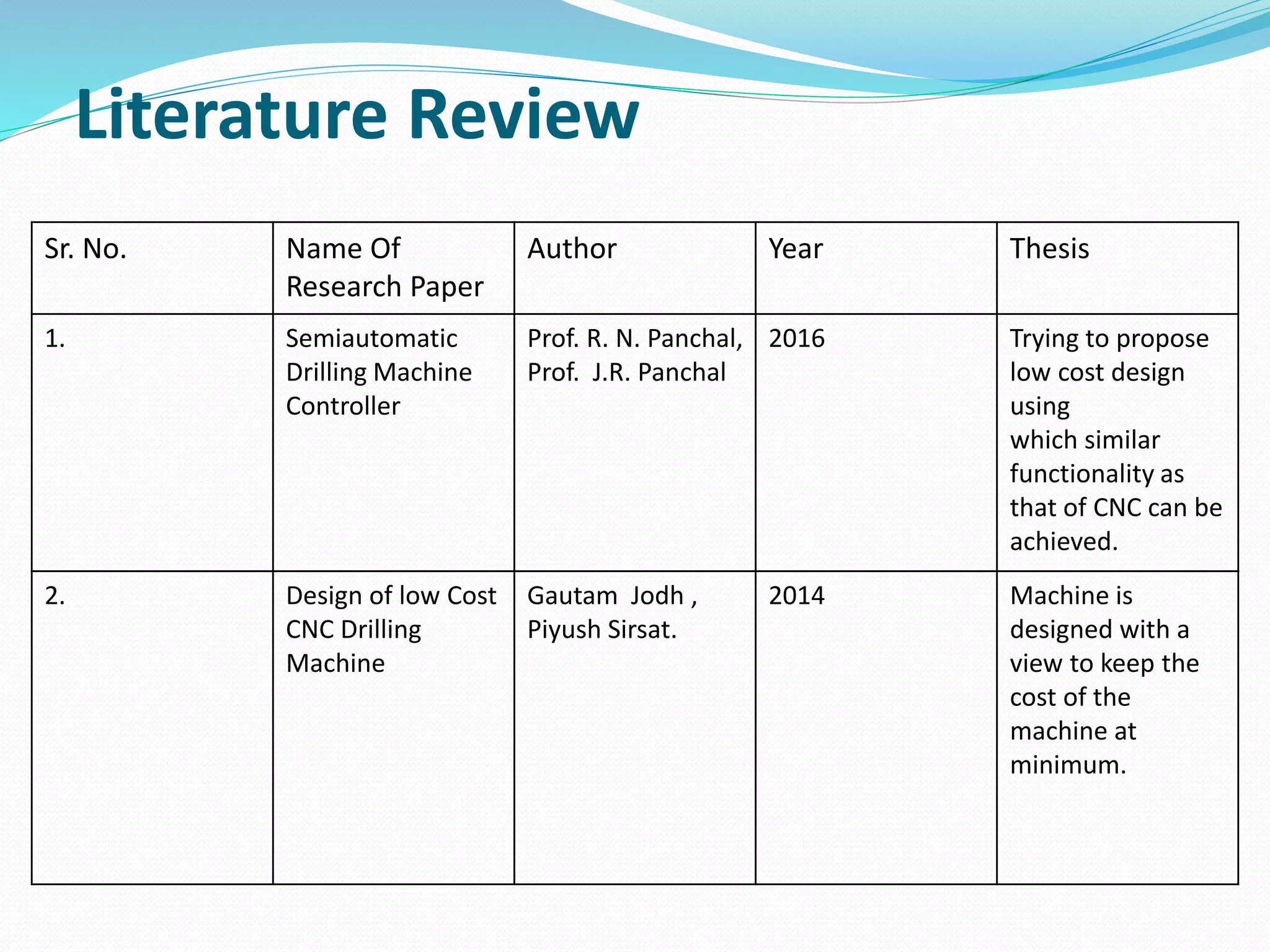


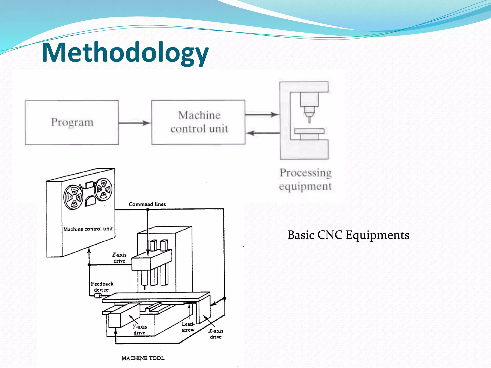


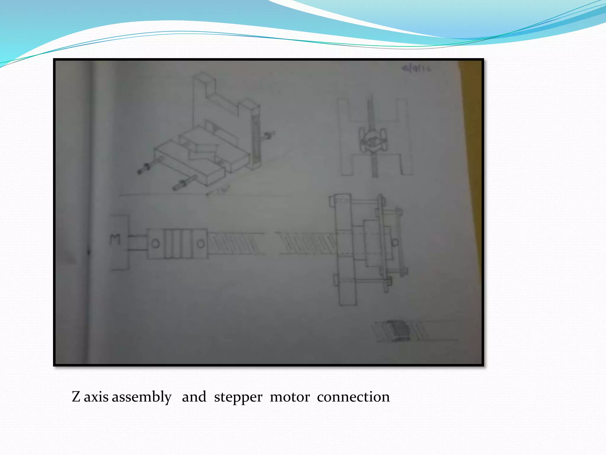
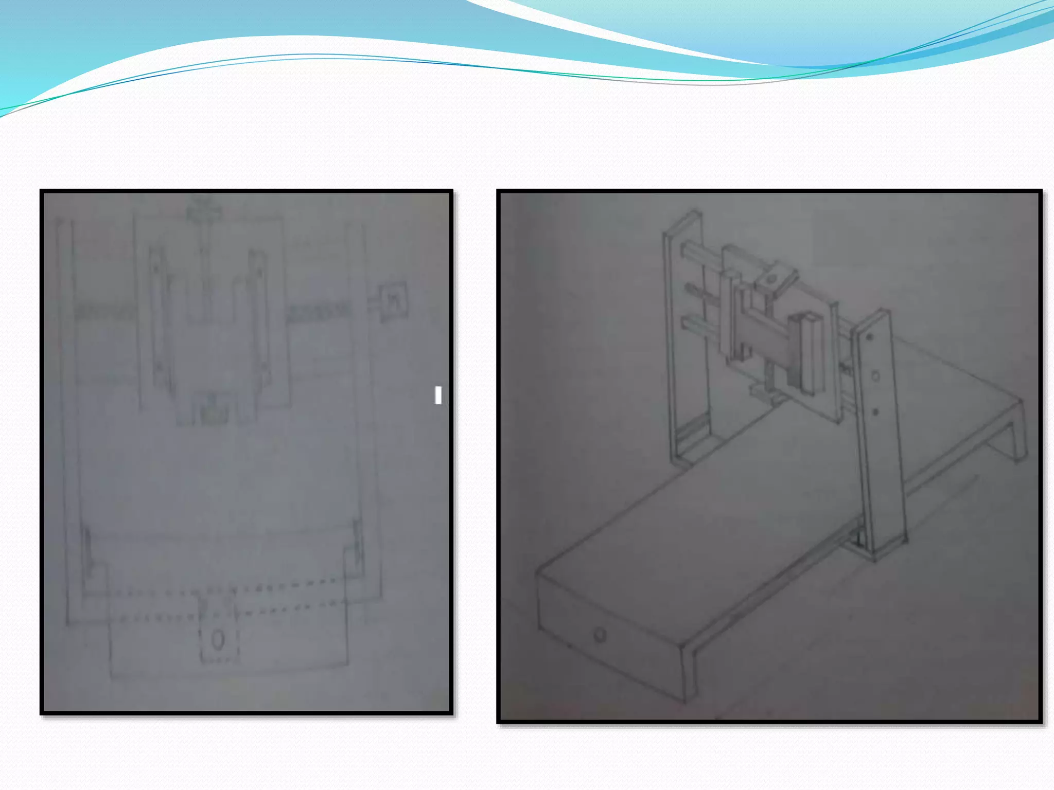
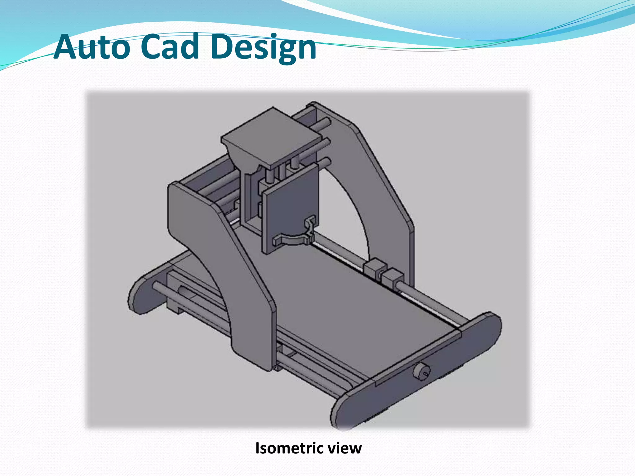
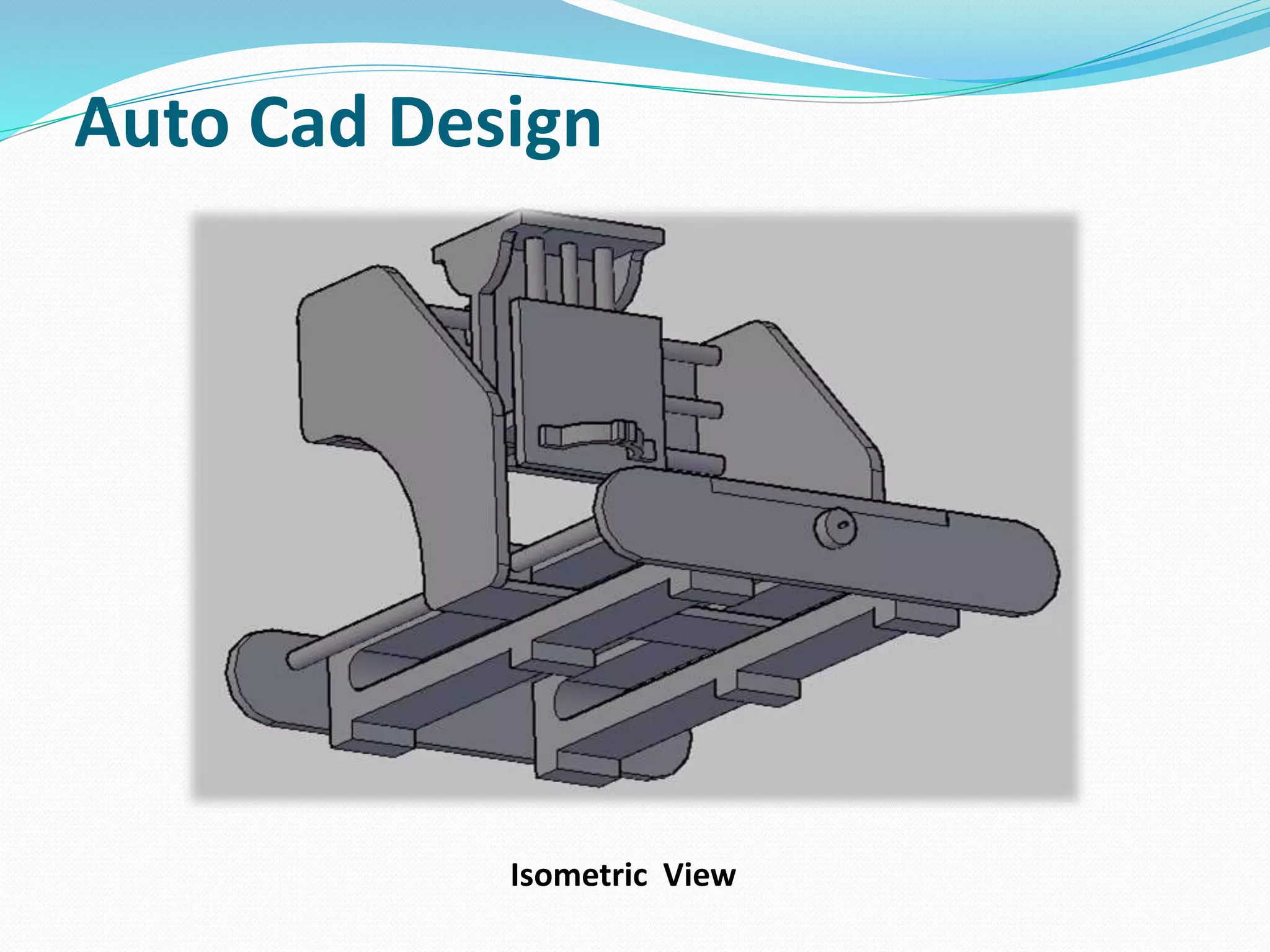
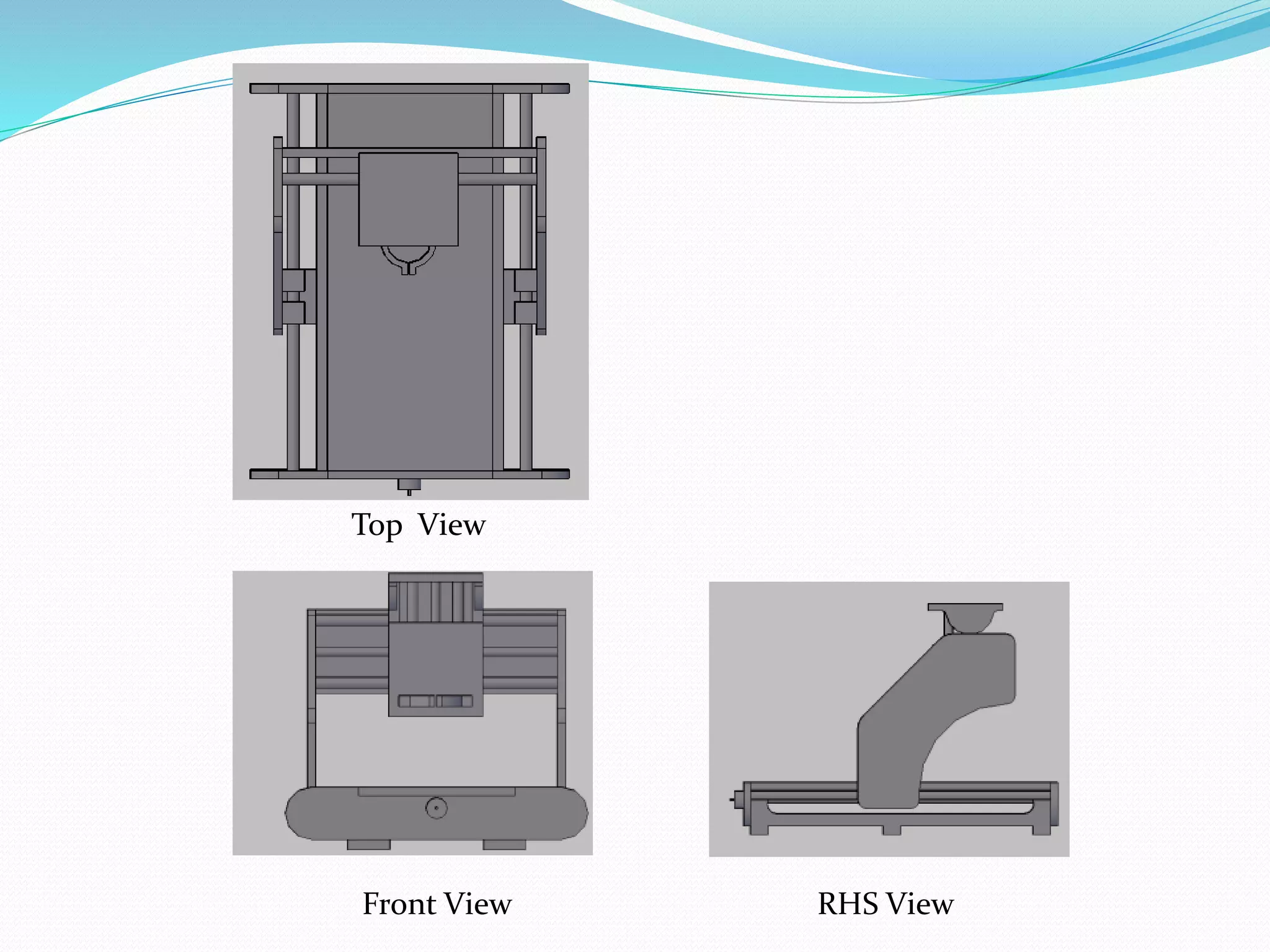
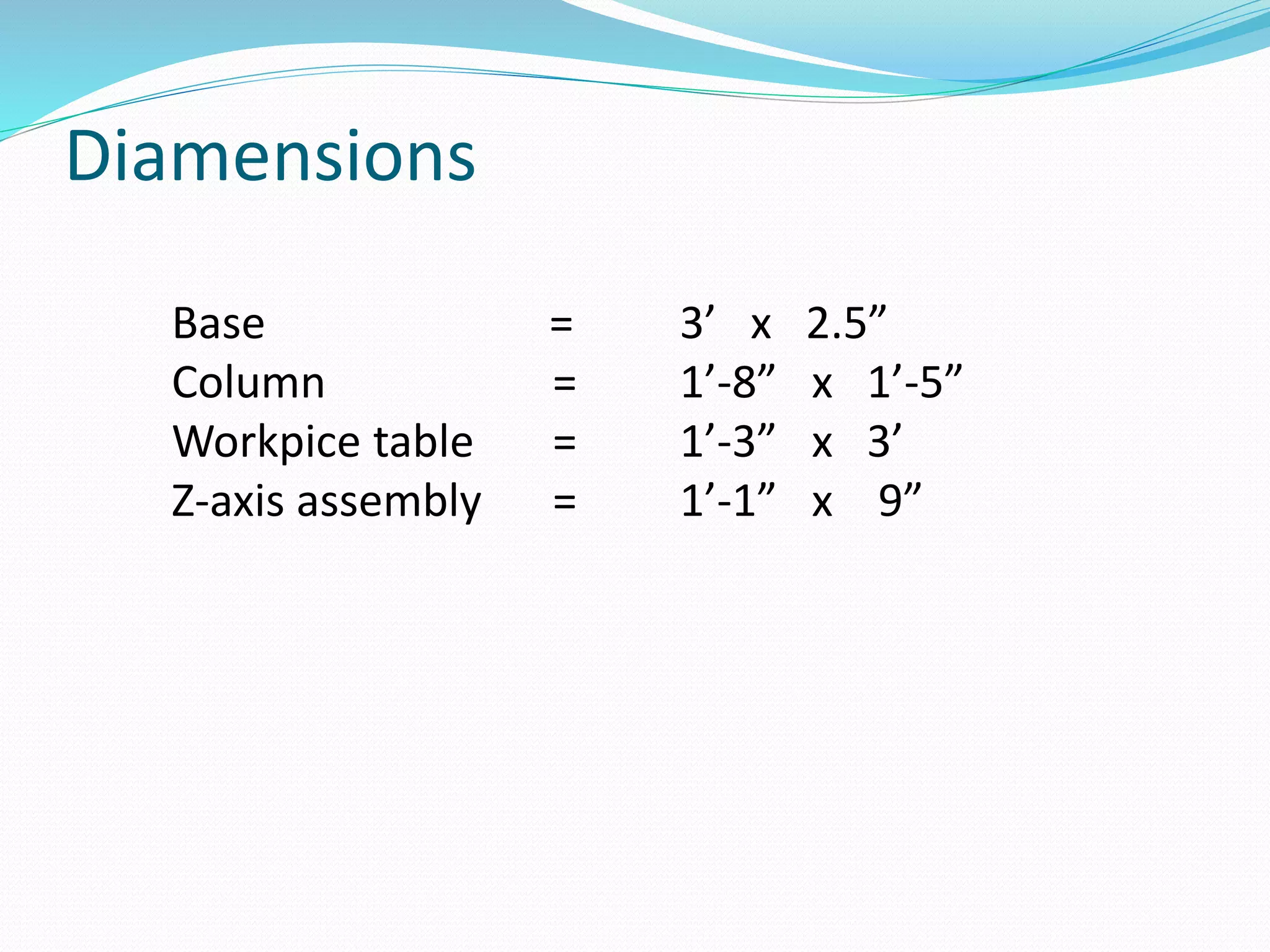


The document describes a seminar on the design and fabrication of a low-cost CNC milling machine, emphasizing its benefits for hobbyists, small businesses, and educational institutions. It presents a detailed literature review, methodology, and parts involved in the CNC machine, including the use of Arduino for control. The conclusion highlights the increasing demand for precision machining while providing insights into future developments of the CNC machine design.