Download to read offline
![International Research Journal of Engineering and Technology (IRJET) e-ISSN: 2395 -0056
Volume: 04 Issue: 03 | Mar -2017 www.irjet.net p-ISSN: 2395-0072
© 2017, IRJET | Impact Factor value: 5.181 | ISO 9001:2008 Certified Journal | Page 693
3 AXIS DRAWING MACHINE
Anubhavi S. Pawar1, Monali J. Halunde2, Shabanam M. Nayakawadi3, Ms. P. P. Mirajkar4
1Student, Department of Electronics and Telecommunication, Annasaheb Dange College of Engineering and
Technology, Ashta, Maharashtra, India
2Student, Department of Electronics and Telecommunication, Annasaheb Dange College of Engineering and
Technology, Ashta, Maharashtra, India
3Student, Department of Electronics and Telecommunication, Annasaheb Dange College of Engineering and
Technology, Ashta, Maharashtra, India
4Assistant Professor, Department of Electronics and Telecommunication, Annasaheb Dange College of
Engineering and Technology, Ashta, Maharashtra, India
---------------------------------------------------------------------***---------------------------------------------------------------------
Abstract - This paper discusses design and
implementation of low cost 3 Axis Drawing Machine using
Arduino controller based on computerized numerical
controller (CNC) machine and open sourcesoftware(G-code
and GRBL) for controlling whole operation. Computer
numeric control (CNC) machine plays an important role in
the field of automation. The main aim of this project is to
reduce time consumed and it reduces human involvement
which eventually reduces rate of error and also increase the
accuracy of the production. Thecommunicationbetweenthe
open source software (G-code and GRBL) and hardware
(Arduino and CNC shield) is to be done with the help of USB.
1. INTRODUCTION
CNC Machining is a process usedinthemanufacturingsector
that involves the use of computers to control machine tools.
Tools that can be controlled in this manner include lathes,
mills, routers and grinders. The CNC in CNC Machining
stands for Computer Numerical Control. CNC – Computer
Numerical Control – Taking digitized data, a computer and
CAM program is used to control, automate, and monitor the
movementsofa machine. The CNC controller works together
with a series of motors and drive components to move and
control the machine axes, executing the programmed
motions. Open source microcontroller platform Arduino is
used for control of the motors, and open source software is
used for executing the G code for machining applications.
Several authors have studied the development of such
machines on a smaller, low-cost scale. For example,
V.K. Pabolu and K.N.H. Srinivas [4] have designed and
implemented a three axis CNC machine using an 8-bit
microcontroller. The development is in .Net platform using
C# programming language on a Windows XP computer, but
the motors have limited power.
T. Andrei and I. Nae [5] have developed a simpler
commercial size CNCrouter running withMach3softwareon
a desktop PC, but requiring a parallel port.
P.A. Sherring da Rocha Jr., R.D.S. Souza,and M.Emilia deLima
Tostes [6] have presented a prototype CNC machine under
development running on a PC with LabVIEW which has
advantage of ease of visual programming tools. The PC is
interfaced with low-cost embedded microcontrollers
through the serial port. The CNC machine designsaboverely
on the use of stepper motors of limited power in open loop
mode.
Xu, Y. Li, J. Sun, and S. Wang [8] discuss results of research
on an open CNC system using Windows PC with a four-axis
motion controller.
A major new development in computer technology is the
availability of low-cost open source hardware, such as the
Arduino micro-controller platform.[10]
1.1 Objectives -
The idea behind the fabrication of low cost 3 Axis Drawing
Machine is to fulfill demand of small scale industries. An
advantage of open source hardware is that a wide variety of
ready-to-use software is available for them on the Web,
therefore the prototyping and development times are
drastically reduced. Moreover, a wide range of low-cost
interfaces, sensors, and accessories such as Arduino shields
are also available on the Internet, along with clear
instructions, examples, and applicable program code.
In this paper, the development of a prototype 3-axis CNC
Router using Arduino-based control system is presented
with following specifications:
• Low cost
• Easily operable
• Easy interface
• Flexible
• Low power consumption](https://image.slidesharecdn.com/irjet-v4i3184-171220101327/75/3-Axis-Drawing-Machine-1-2048.jpg)
![International Research Journal of Engineering and Technology (IRJET) e-ISSN: 2395 -0056
Volume: 04 Issue: 03 | Mar -2017 www.irjet.net p-ISSN: 2395-0072
© 2017, IRJET | Impact Factor value: 5.181 | ISO 9001:2008 Certified Journal | Page 696
used for micro stepping. DIR is directioninputpinwhich will
move stepper motor according to the given dimensions.
Third pin is directly grounded.
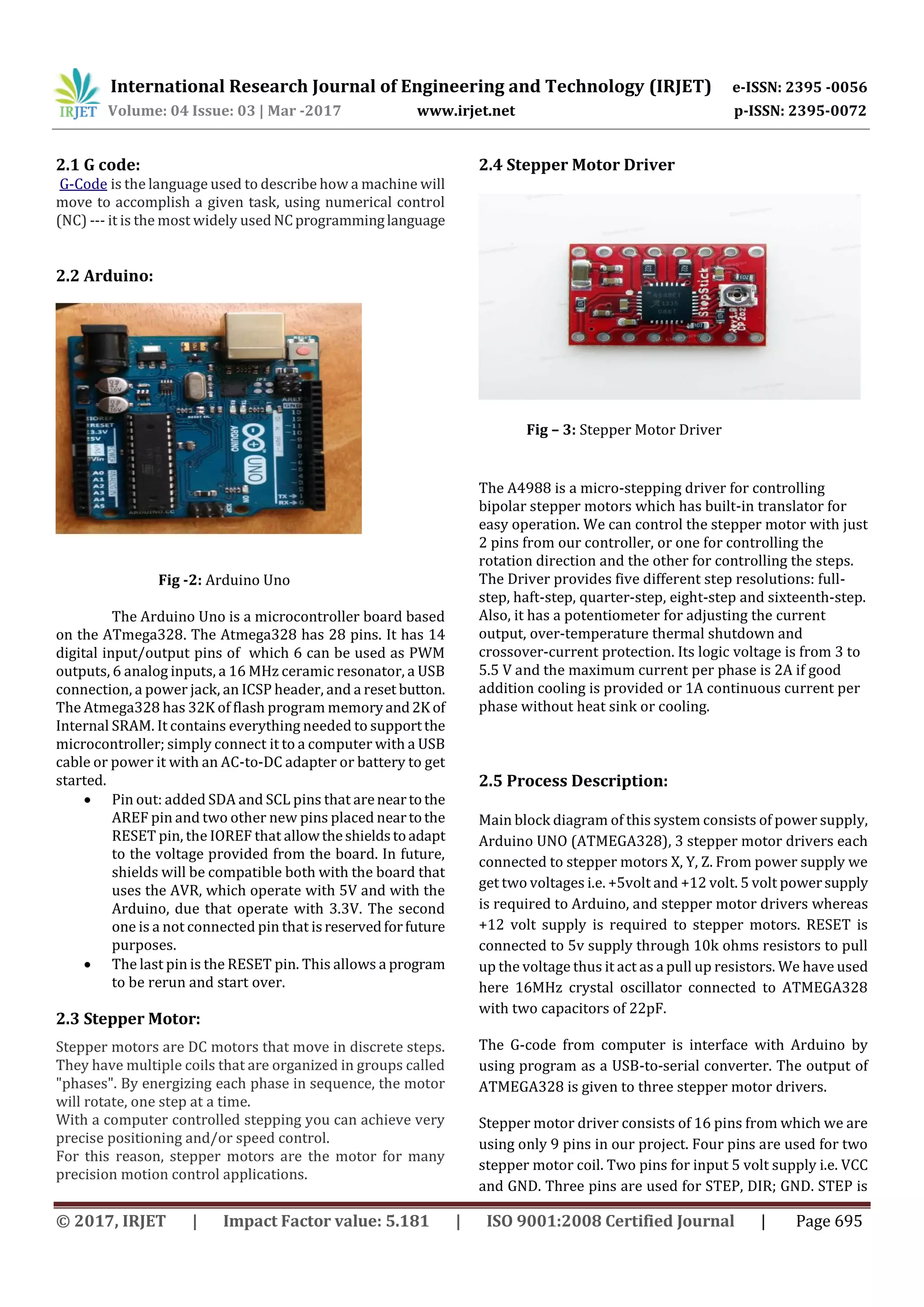
3. Hardware Implementation:
3. CONCLUSION
This paper has presented the results of
development of a Low cost three-axis drawing machine
suitable for drawing letters andimageswithbetteraccuracy.
This setup of hardware with a combination of software
reduces the work load. G code make easy to find the
information of locations of all stepper motor moving, as the
status of our moving motor are directly seen on computer
hence we can start or stop the machine whenever we
needed. Making a small machine brings a flexibility to do
work.
REFERENCES
[1] Yung C. Shin, Henry Chin, Michael J. Brink,
―Characterization of CNC machining centers,‖ Journal of
Manufacturing Systems,1991
[2] Heisel, M Gringel, ―Machine Tool Design Requirements
for High Speed Machining‖,1999
[3] M Kumar, V Puttige, ―low cost automation for CNC
machining center‖, IJMET, Vol. 3.
I. Pahole, L. Rataj, M. Ficko, S. Klancnik, S.Brezovnik, M.
Brezocnik, and J. Balic,"Construction and evaluation of low-
cost tableCNC milling machine",2009
[4] V.K. Pabolu and K.N.H. Srinivas, "Design and
implementation of a three dimensional CNC machine",2010.
[5] T. Andrei and I. Nae, "Practical applicationsperformed by
a stepper motor CNC router",2010
[6] P.A. Sherring da Rocha Jr., R.D.S. Souza, and M.Emilia de
Lima Tostes, "Prototype CNC machinedesign",2012
[7] Ms. P. P. Mirajkar, Ms. Kavathekar Jyoti, Ms. Madhuri
Kamble, “AUTOMATIC POWER FACTOR RELAY USING PIC
CONTROLLER” is published in IJARECE, ISSN 2278-909X,
Volume 5, Issue 4, pp. 808-811 , April -2016
[8] Xu, Y. Li, J. Sun, and S. Wang, "Research and development
of open CNC system based on PC and motion
controller",2012.
[9] Ms. P. P. Mirajkar, Prof. S.D. Ruikar, “WAVELET BASED
IMAGE FUSION TECHNIQUES” is published in CIIT
International Journal of Digital Image Processing, Volume 4,
No. 15, September 2012
[10] www.arduino.cc](https://image.slidesharecdn.com/irjet-v4i3184-171220101327/75/3-Axis-Drawing-Machine-4-2048.jpg)


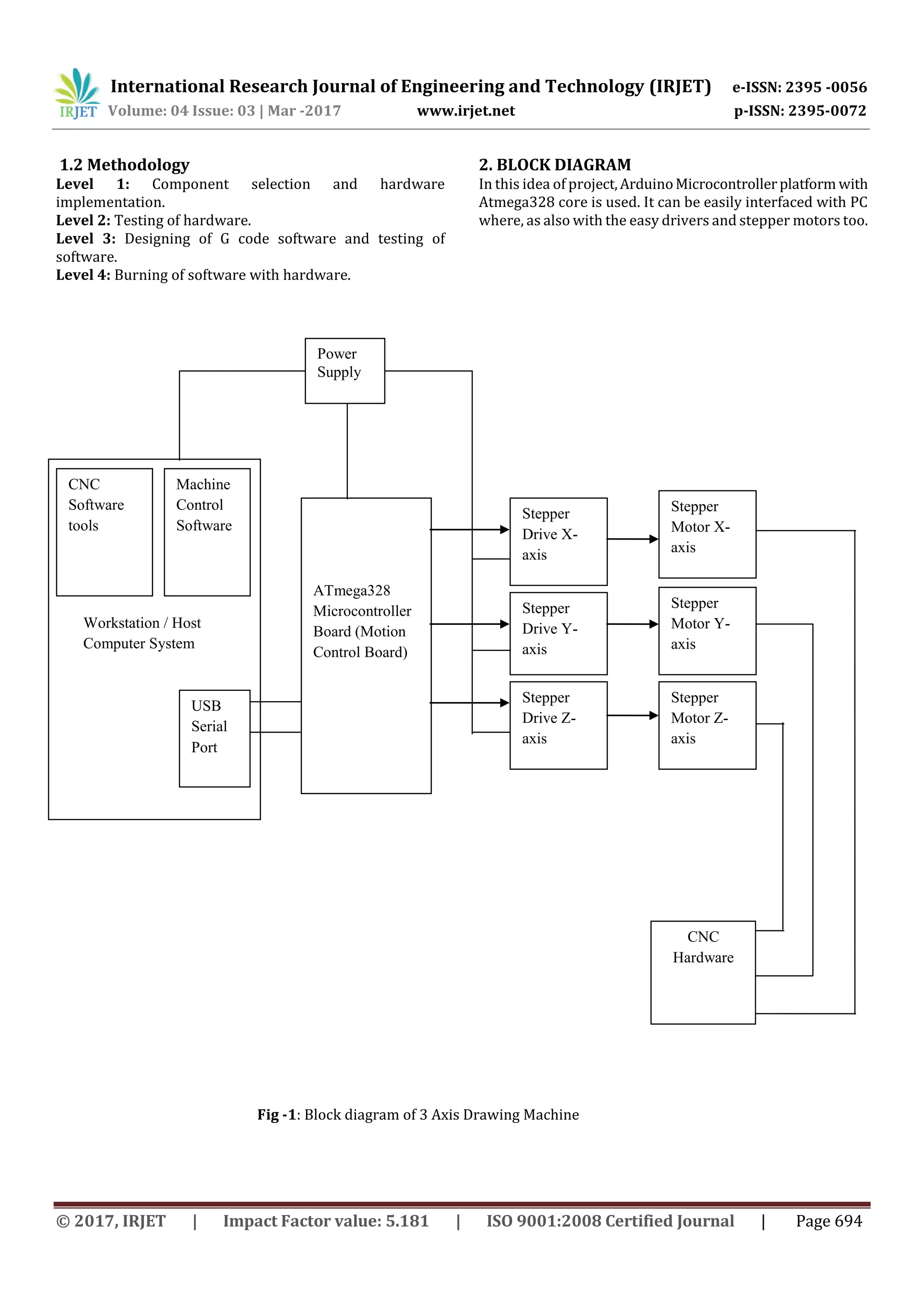
This document describes the design and implementation of a low-cost 3-axis drawing machine using an Arduino controller and open-source G-code and GRBL software. The machine uses stepper motors connected to an Arduino board via motor drivers to move in the X, Y, and Z axes according to G-code instructions sent from a computer. The goal is to create an affordable CNC machine for small industries that reduces time, human errors, and increases accuracy compared to manual drawing. Hardware components including the Arduino, stepper motors, and motor drivers are discussed. The software uses G-code interpreted by the Arduino to control motor movements. Initial testing showed the setup could accurately draw letters and images.