Downloaded 1,065 times
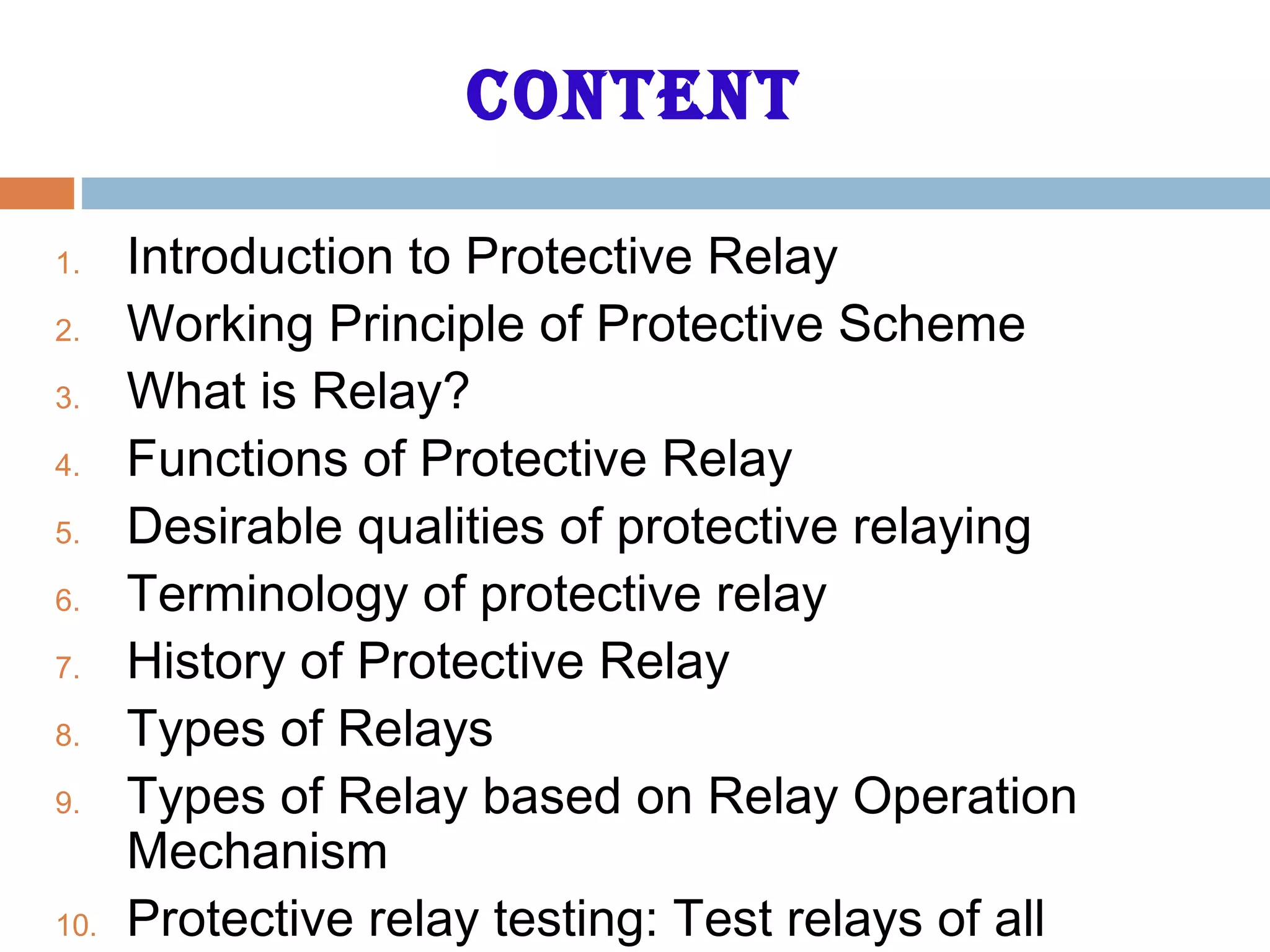


This document provides an overview of protective relays, including: 1. It describes the components that protective relays protect, the working principles of protective schemes, and the functions and desirable qualities of protective relays. 2. It discusses the terminology used in protective relaying and provides a history of protective relays from electromechanical to numerical relays. 3. It describes different types of relays based on characteristics, logic, actuating parameters, operation mechanisms, and applications.
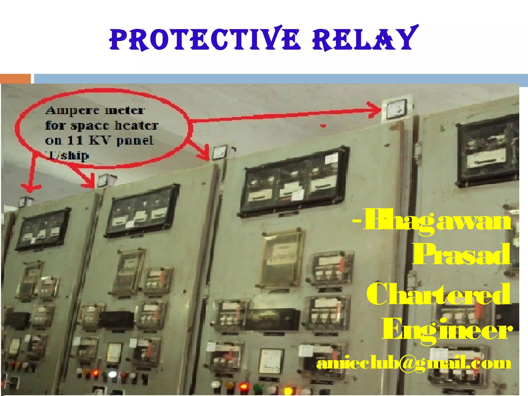
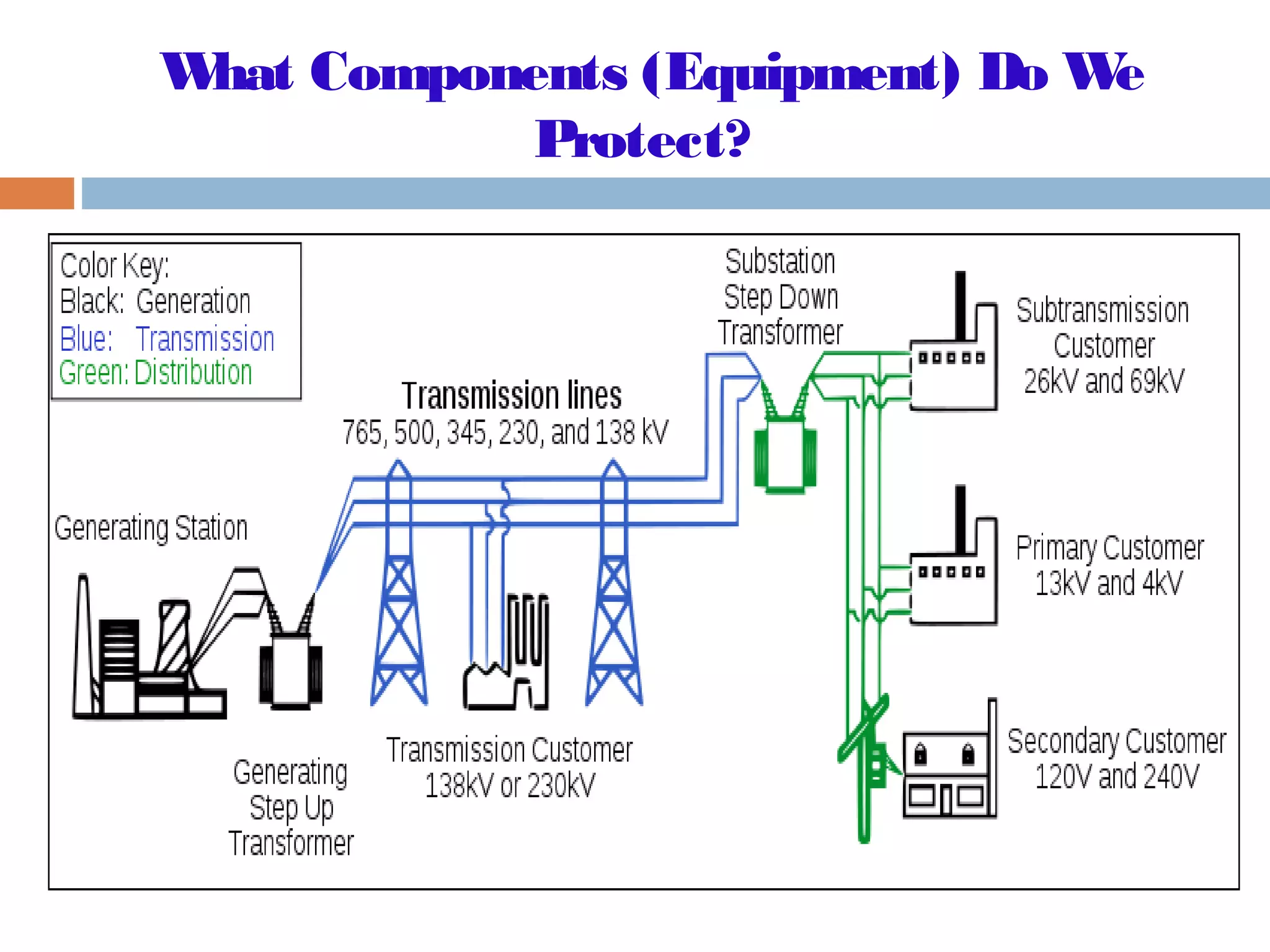
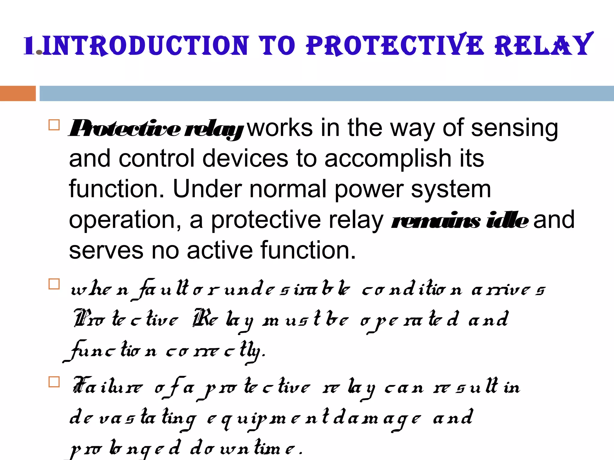
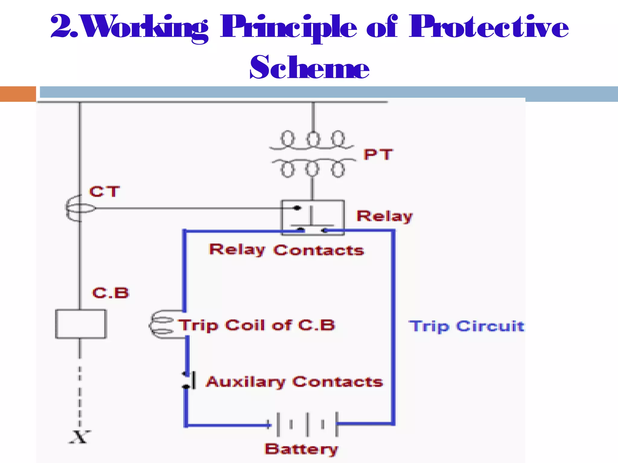
Overview of protective relays and their function in safeguarding electrical circuits and equipment.
Discusses the main functions, qualities like selectivity, reliability, and performance criteria.
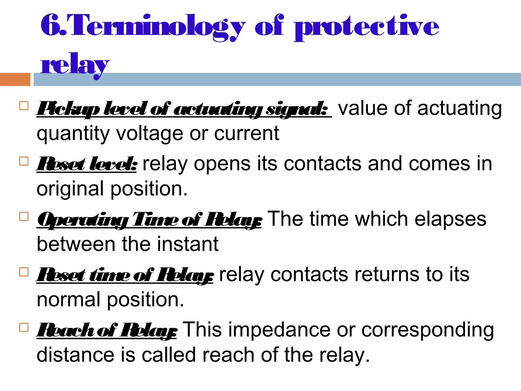
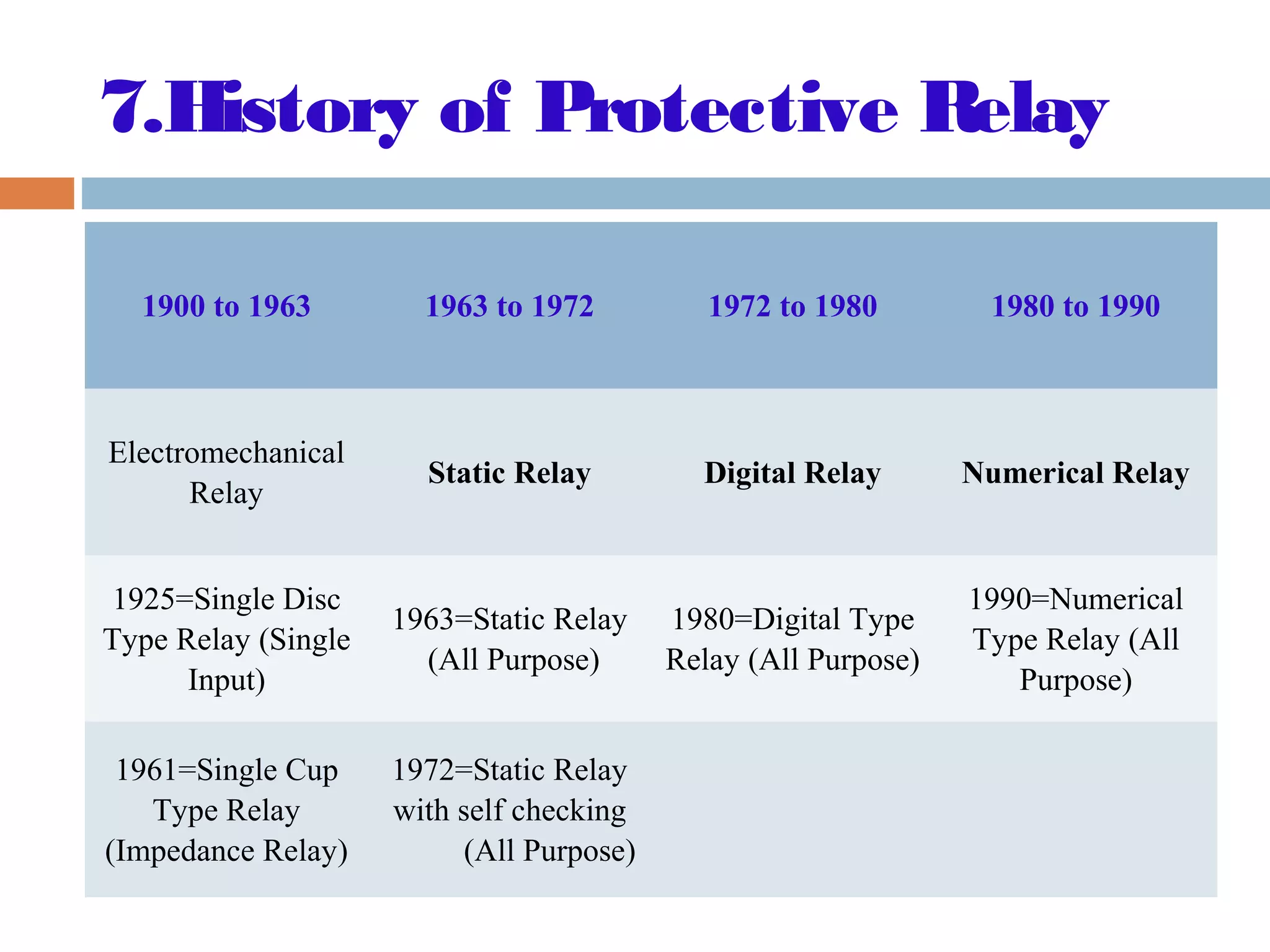
Key terminology used in protective relaying and history from electromechanical to numerical relays.
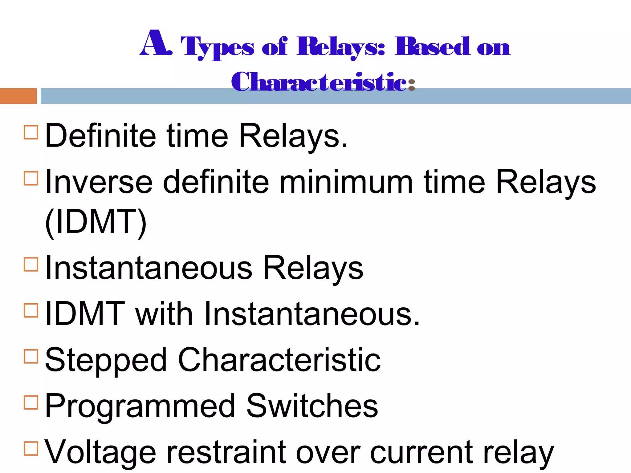
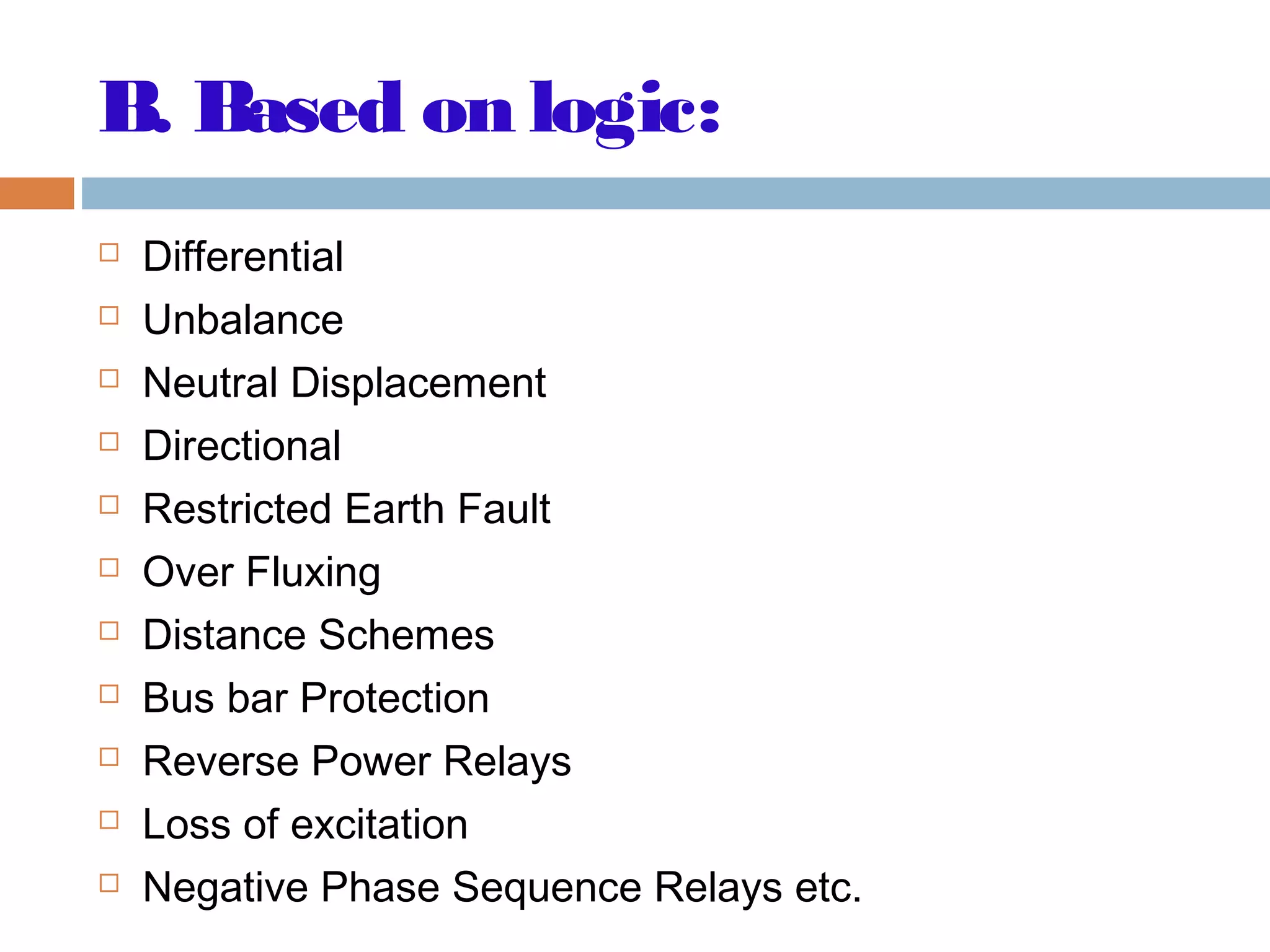
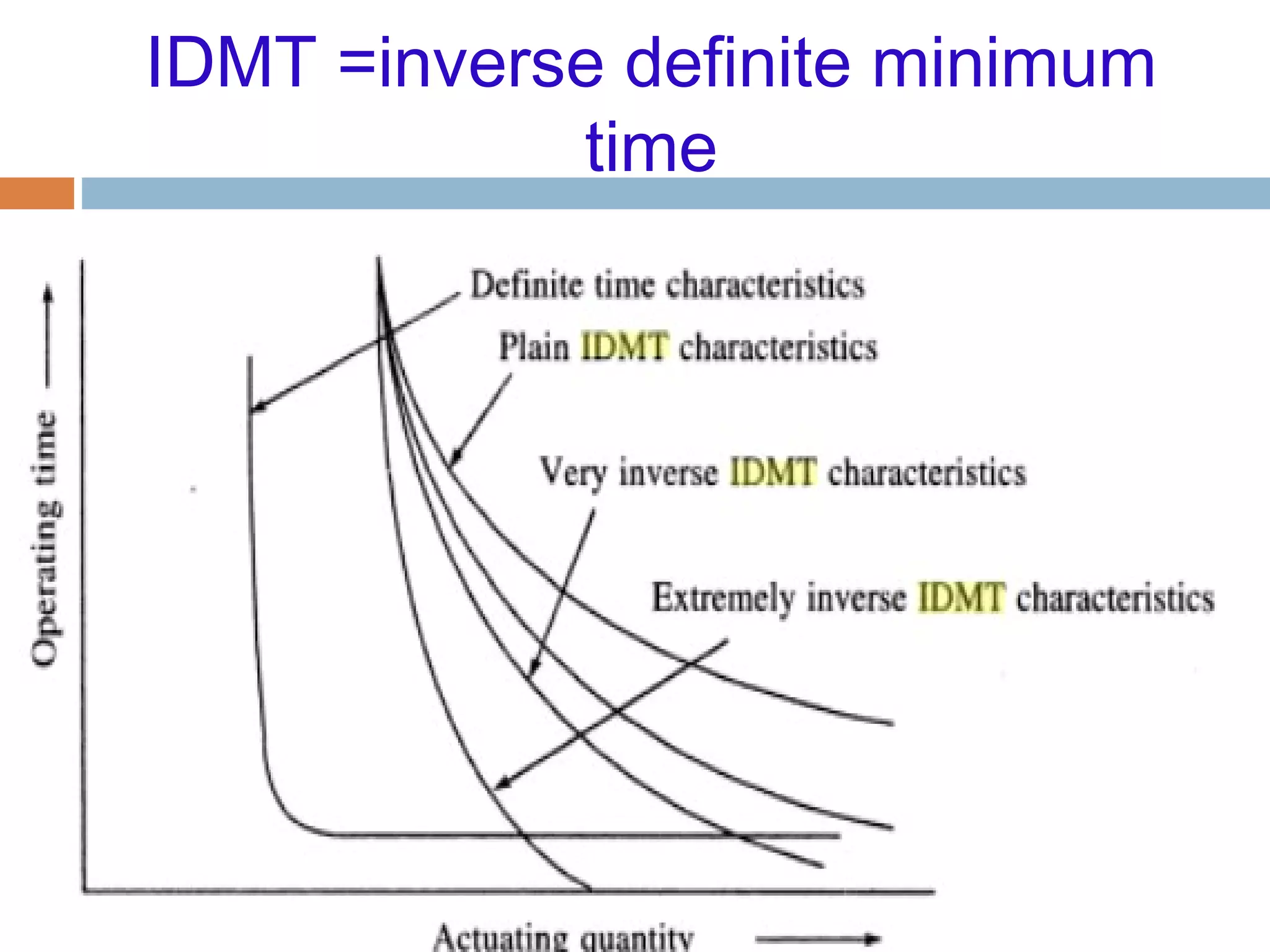
Different types of relays categorized by their characteristics and logical operation principles.
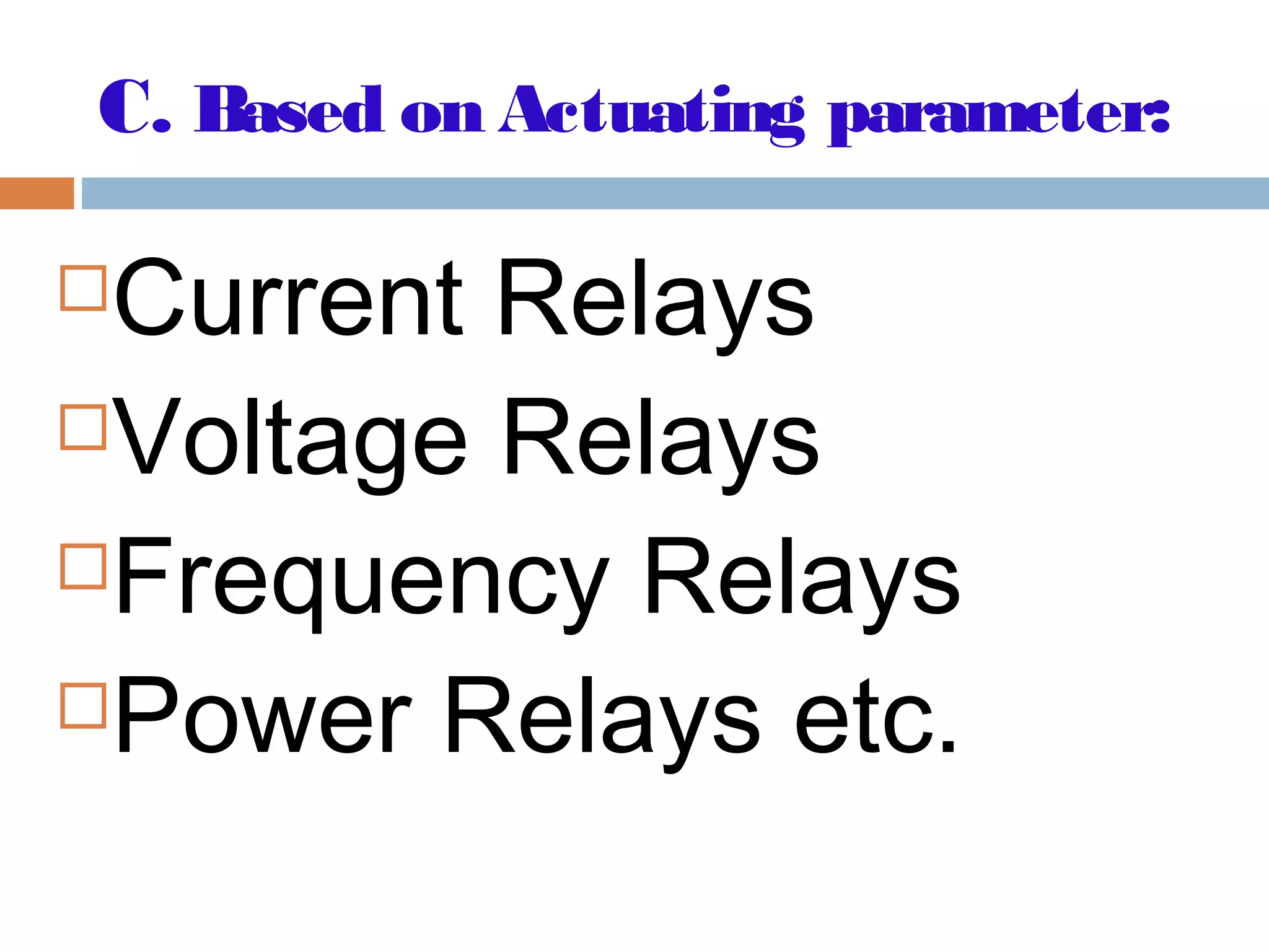
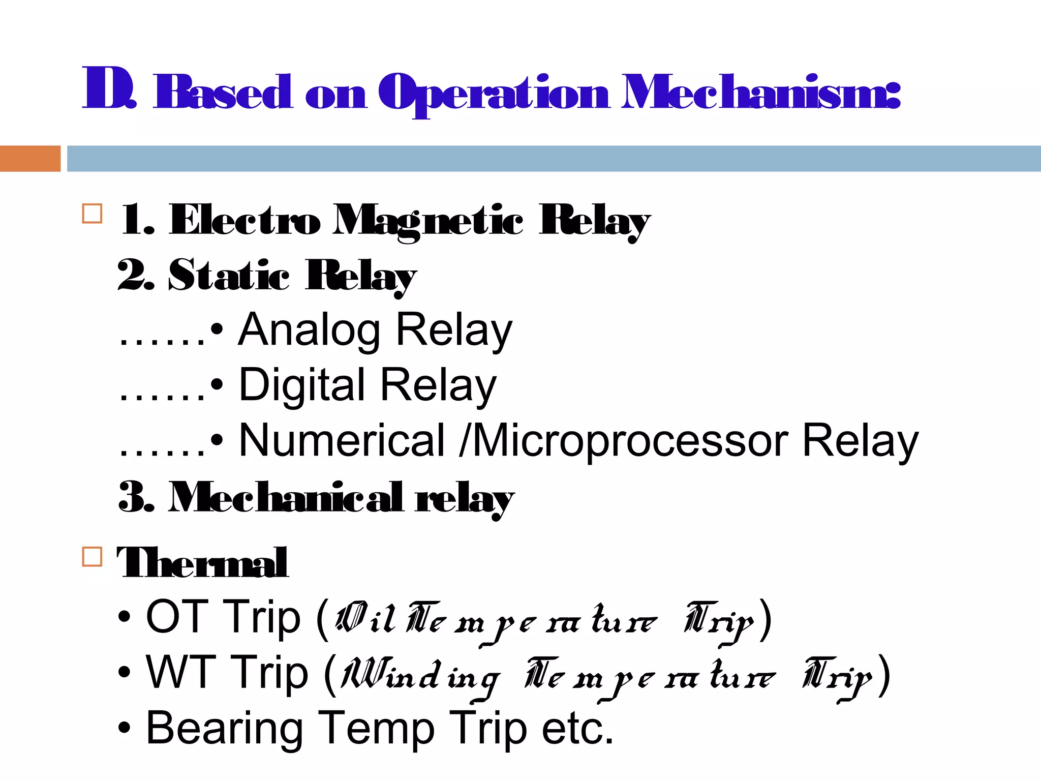
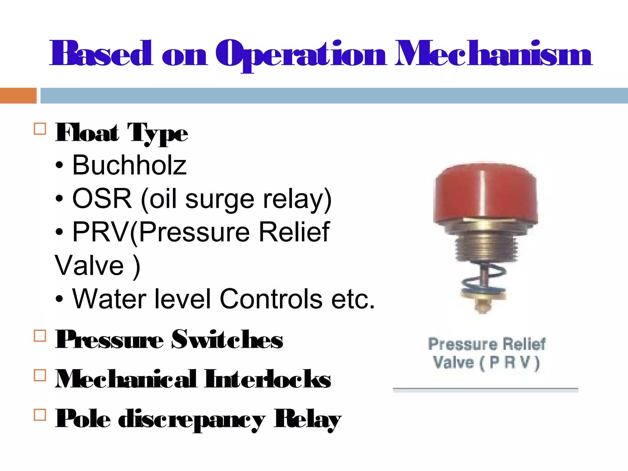
Classification of relays based on actuating parameters and operational mechanisms used.
Details on operational mechanisms, examples of applications for primary and backup relays.
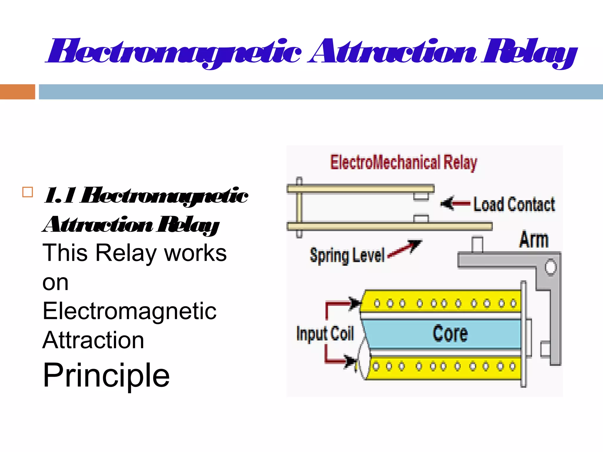
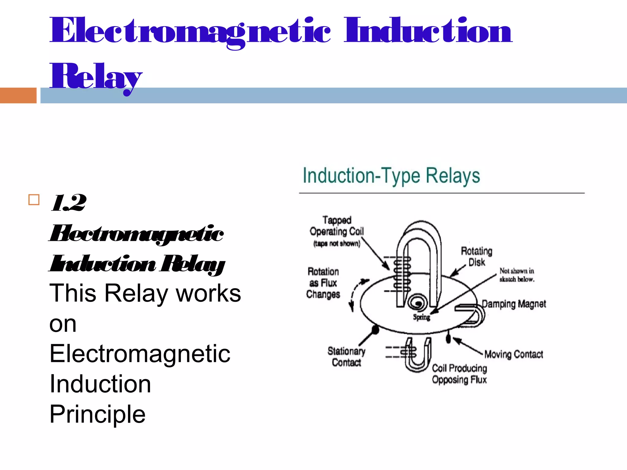
Explanation of electromagnetic attraction and induction relays, including their limitations.
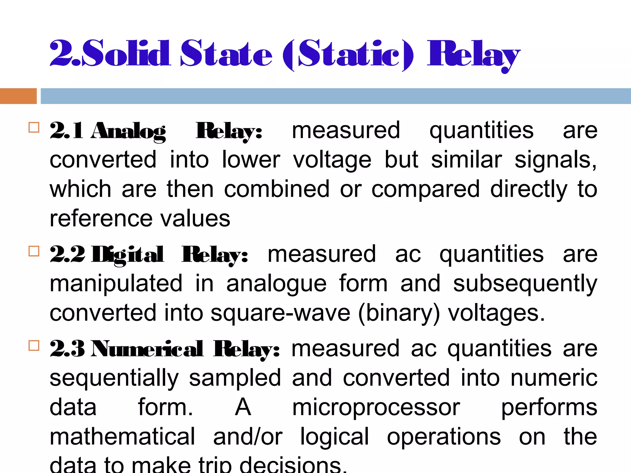
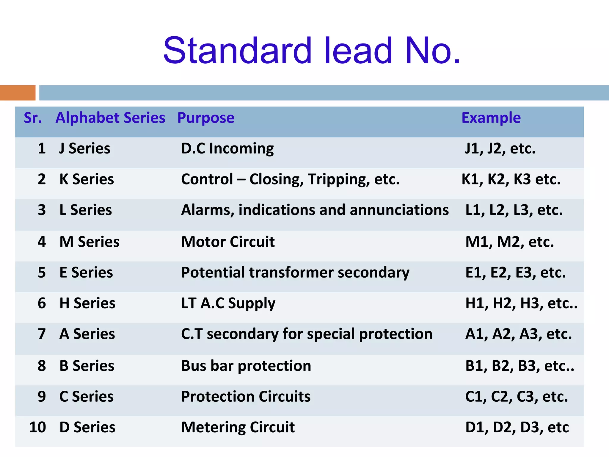
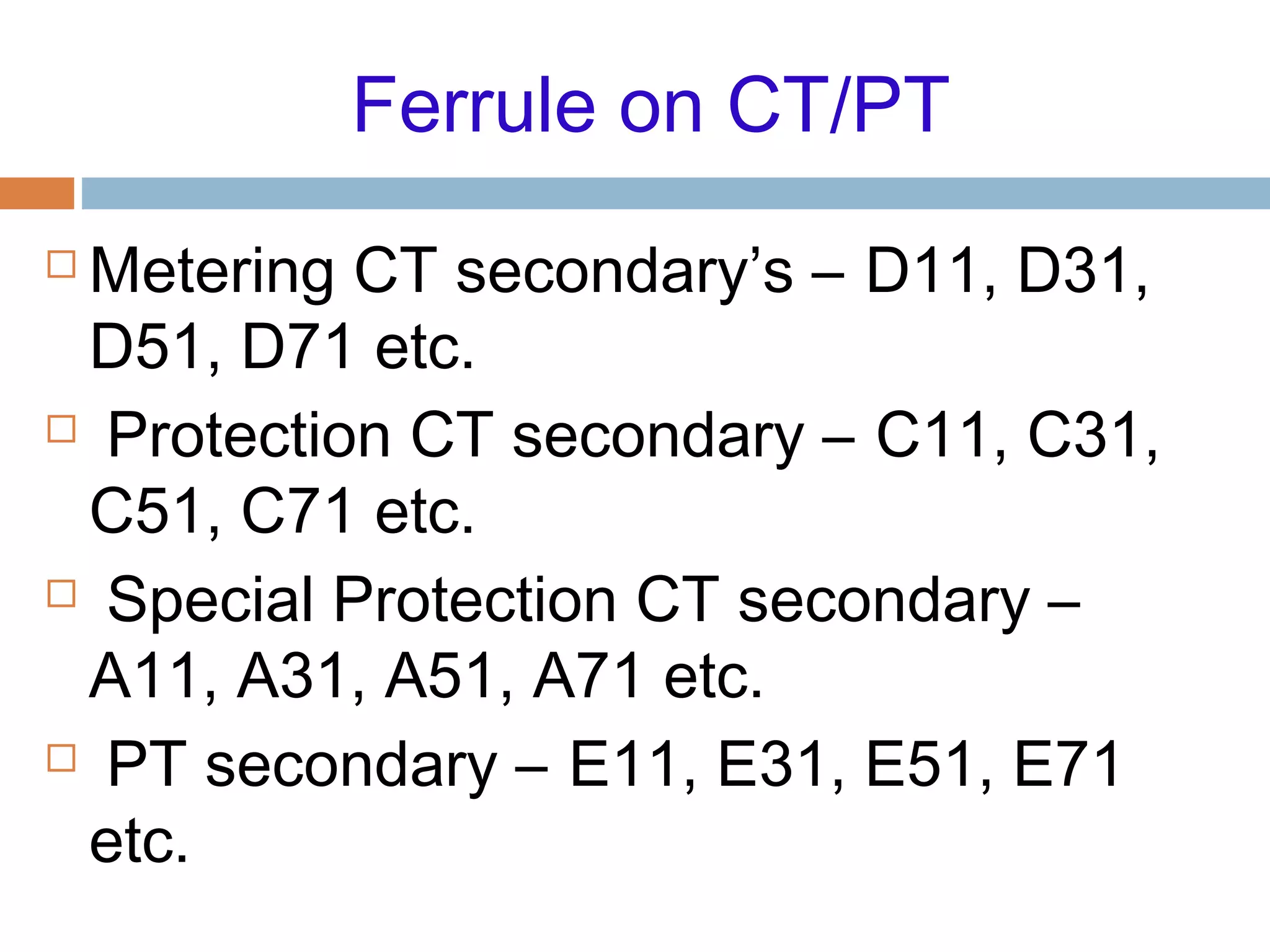
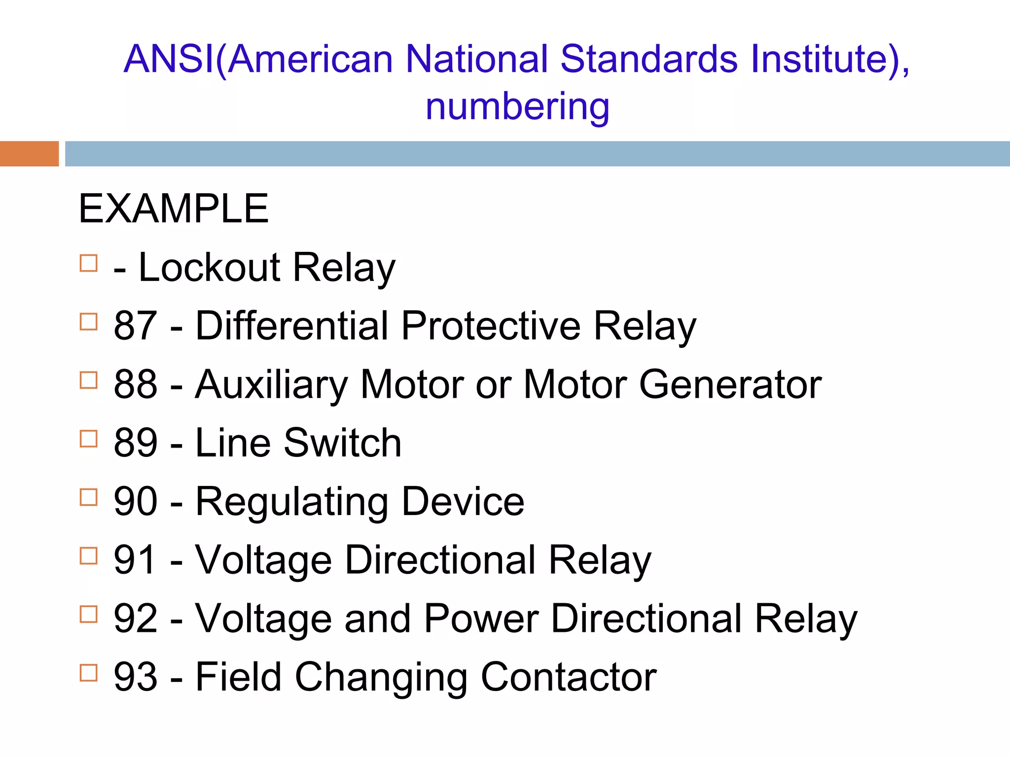
Overview of solid state relays, including analog, digital, and numerical designs with standard labeling.
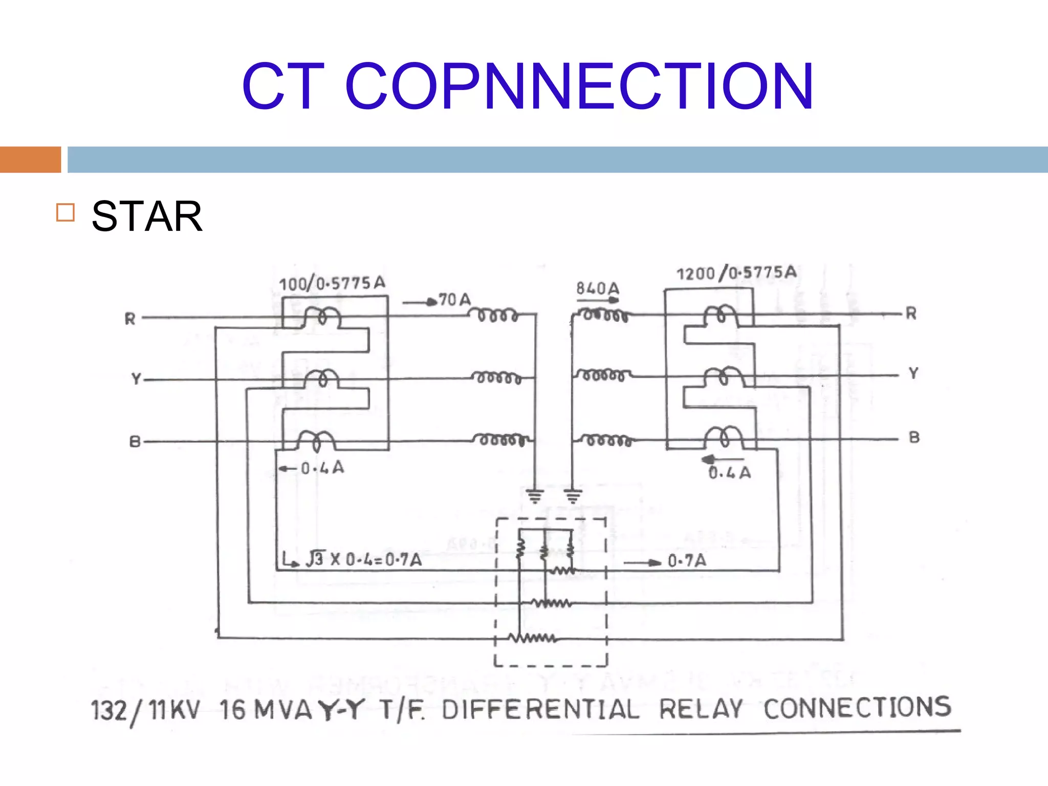
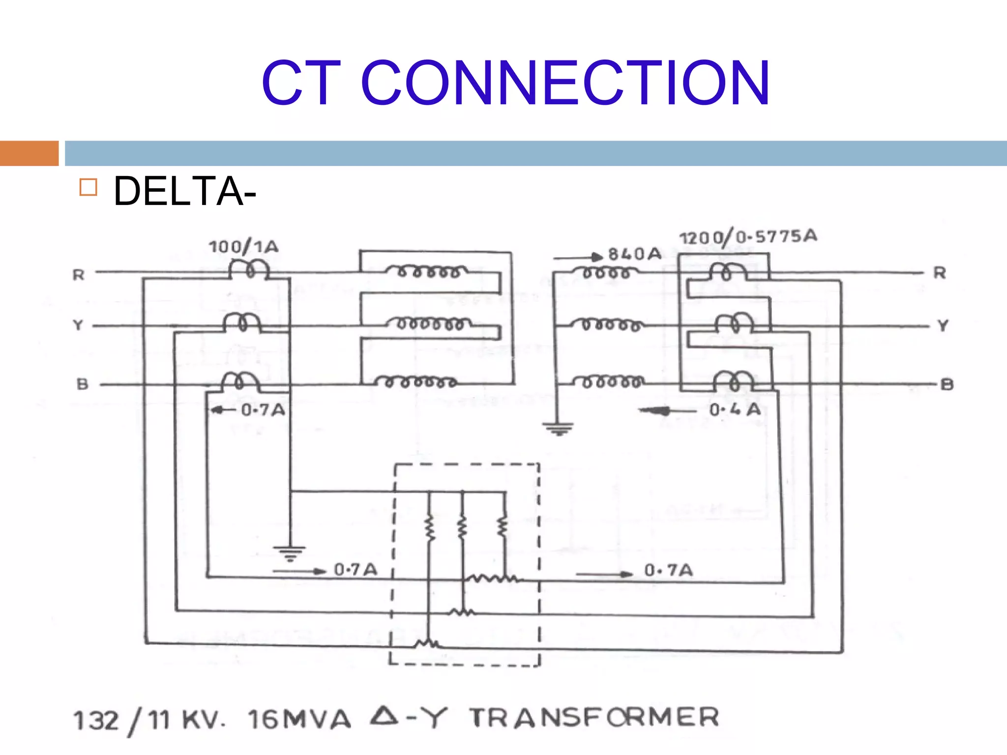
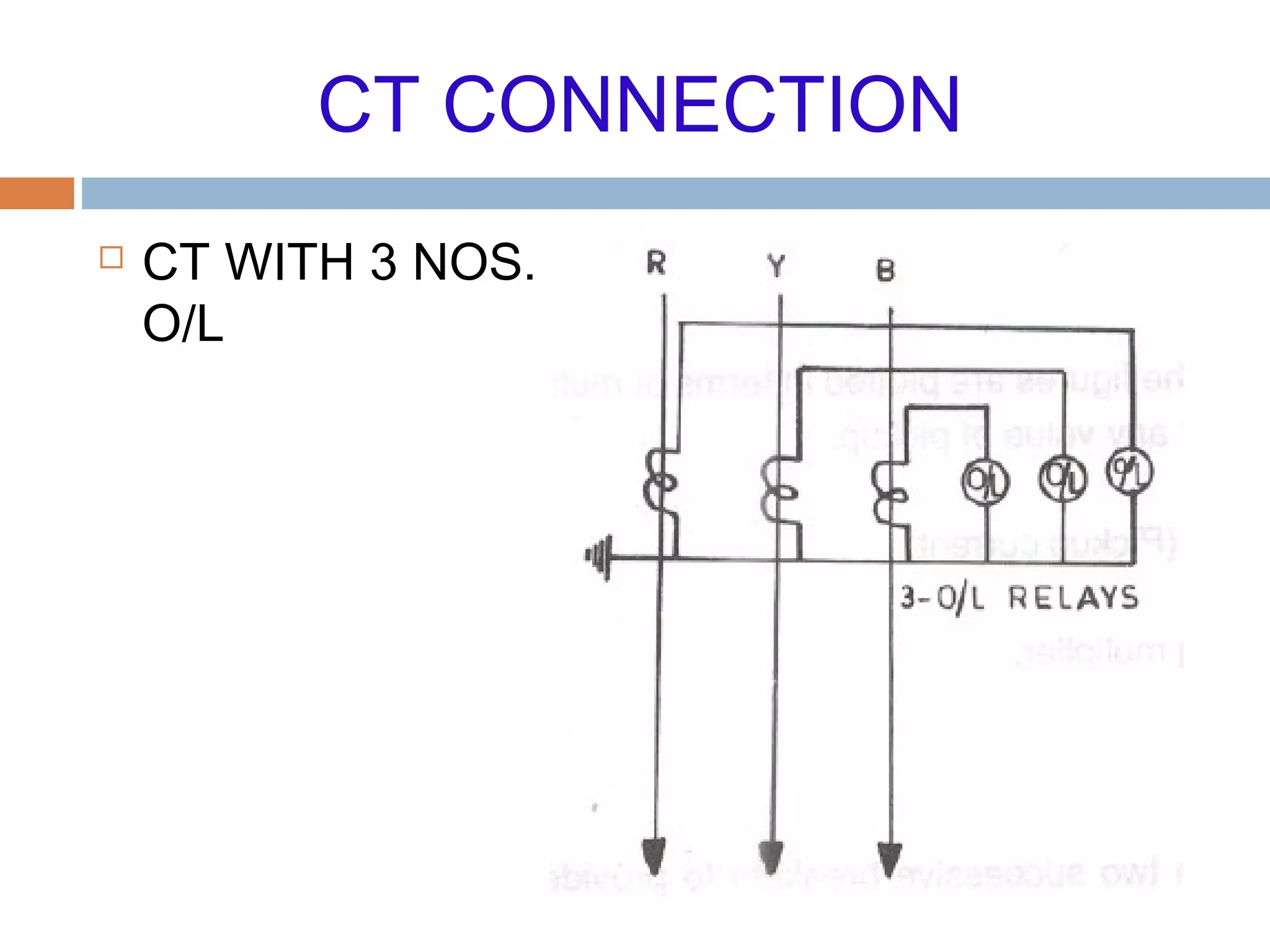
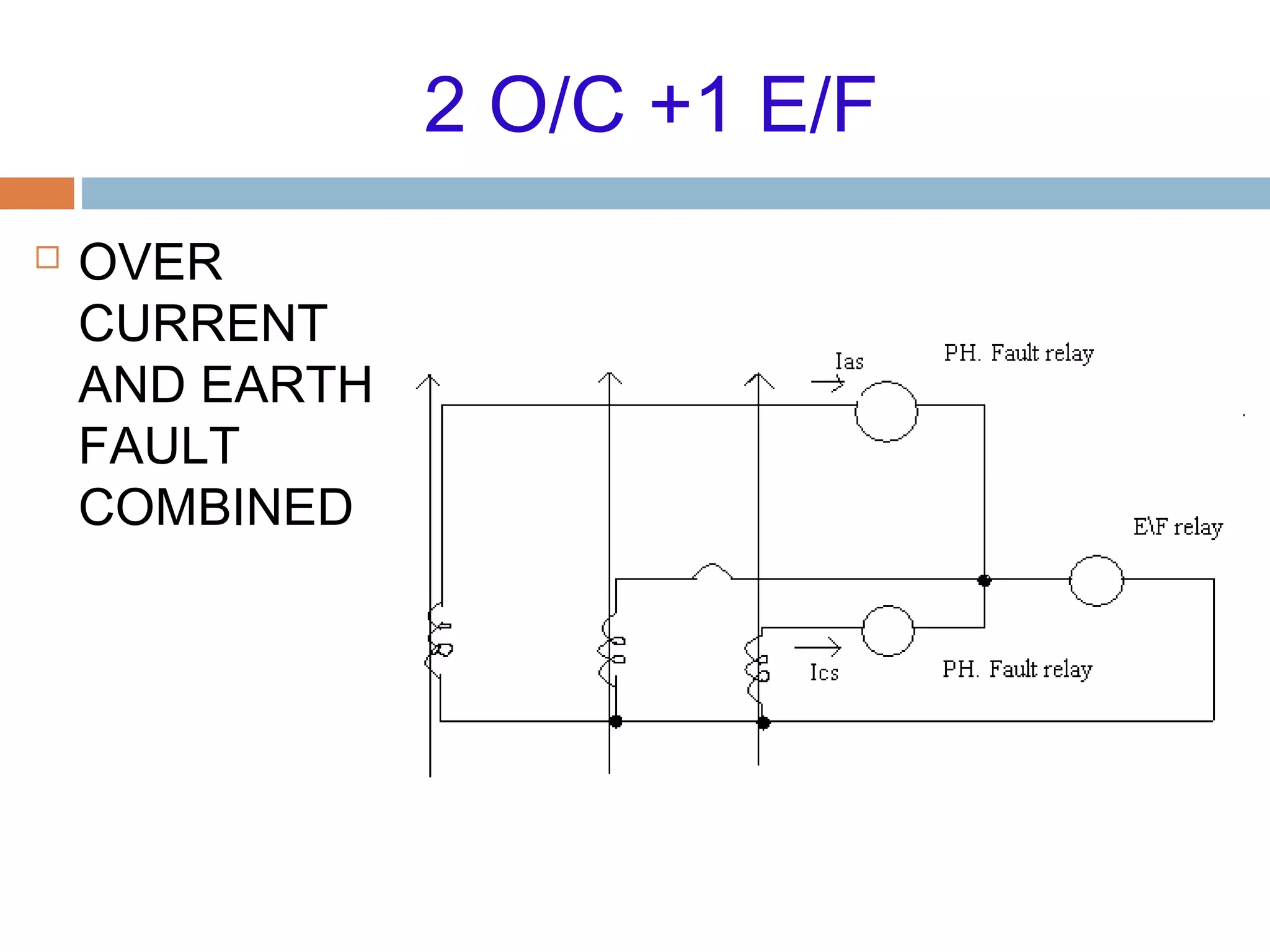
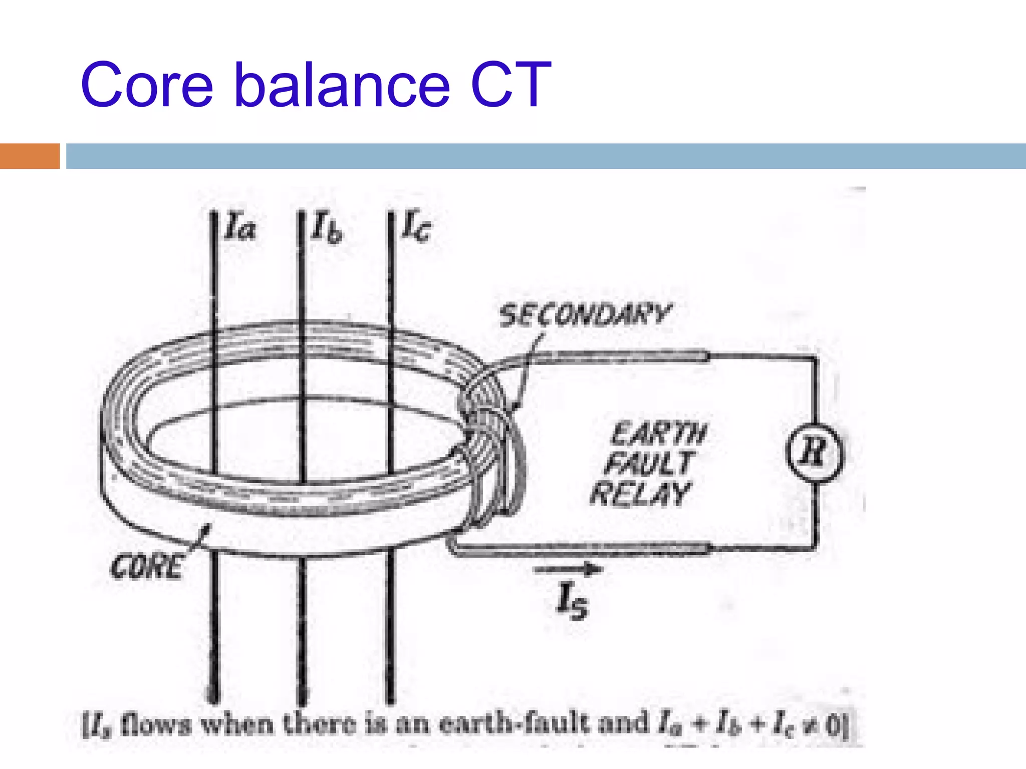
Details on various CT connections and configurations used in protective relay systems.
Concluding remarks and thanks.


![protection of transmission lines[distance relay protection scheme]](https://cdn.slidesharecdn.com/ss_thumbnails/os-exe3-23-may2011-sr-i-776s21tr-lineprotection-120425095503-phpapp02-thumbnail.jpg?width=640&height=640&fit=bounds)


