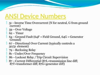
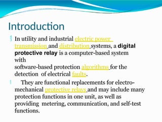
Digital protective relays are computer-based systems used in electric power transmission and distribution systems, offering efficient, multifunctional protection against electrical faults with no mechanical moving parts, thereby requiring minimal maintenance. They allow for advanced signal processing and user-configurable logic, optimizing automation and communication within power networks. Various types of numerical relays exist to cater to different protective functions and operational characteristics.

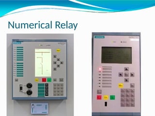

![Numerical Relay Back Side:
Relay back side usually consist of different Terminal
Blocks [TB] for giving the Digital and Analog inputs,
outputs .
TB for Current Transformer inputs
TB for Potential Transformer inputs
TB for Binary Inputs
TB for Binary Outputs
TB for Relay Power Supply
TB for Live status contact
Slots for Communication Ports](https://image.slidesharecdn.com/numerical-relay-ppt-1-converted-240809041905-851449a7/85/Numerical-Relay-PPT-1-convvffverted-pptx-11-320.jpg)