Downloaded 109 times
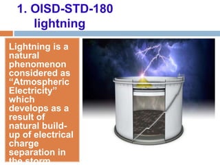
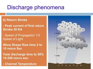
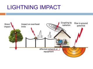
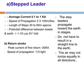
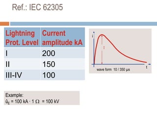
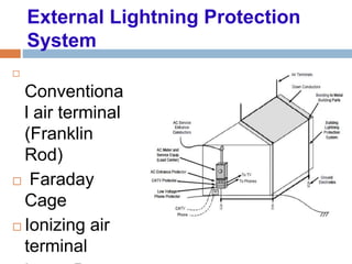


The document outlines the characteristics and dangers of lightning, including its behavior during storms, the risks of direct and indirect strikes, and the necessity for lightning protection systems for buildings and structures. It describes various protection methods such as Franklin rods and Faraday cages, detailing the requirements for installation, materials, and periodic checks for the effectiveness of these systems. Additionally, it emphasizes the importance of proper design and grounding techniques to minimize the risks associated with lightning strikes.


