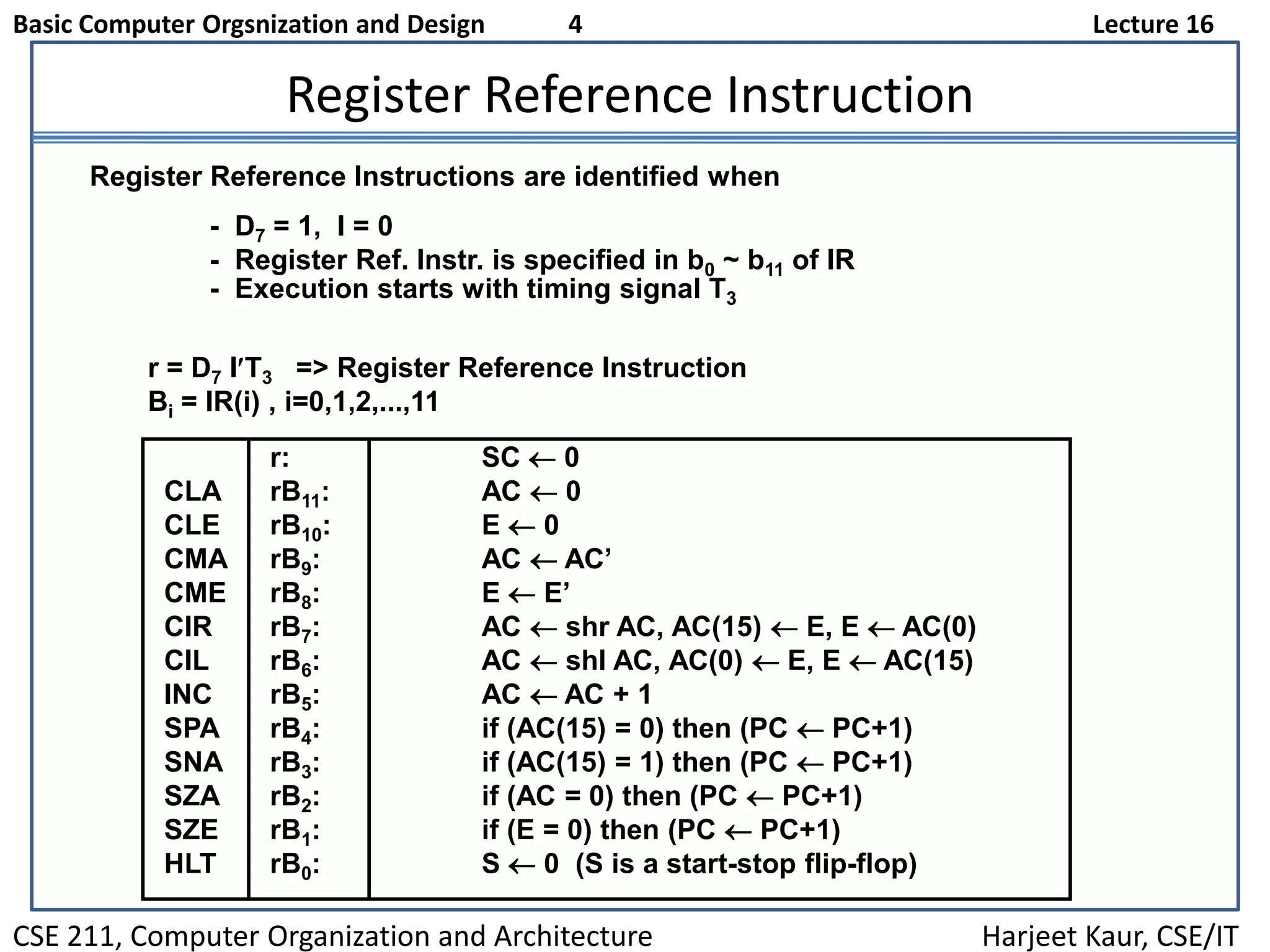
Basic Computer Orgsnization and Design 1 Lecture 16
CSE 211, Computer Organization and Architecture Harjeet Kaur, CSE/IT
Overview
Instruction Codes
 Computer Registers
 Computer Instructions
 Timing and Control
 Instruction Cycle
 Memory Reference Instructions
 Input-Output and Interrupt
 Complete Computer Description
Basic Computer Orgsnization and Design 2 Lecture 16
CSE 211, Computer Organization and Architecture Harjeet Kaur, CSE/IT
Flow Chart (Instruction Cycle)
= 0 (direct)
Start
SC <-- 0
AR <-- PC
T0
IR <-- M[AR], PC <-- PC + 1
T1
AR <-- IR(0-11), I <-- IR(15)
Decode Opcode in IR(12-14),
T2
D7
= 0 (Memory-reference)(Register or I/O) = 1
II
Execute
register-reference
instruction
SC <-- 0
Execute
input-output
instruction
SC <-- 0
M[AR]<--AR Nothing
= 0 (register)(I/O) = 1 (indirect) = 1
T3 T3 T3 T3
Execute
memory-reference
instruction
SC <-- 0
T4
Basic Computer Orgsnization and Design 3 Lecture 16
CSE 211, Computer Organization and Architecture Harjeet Kaur, CSE/IT
Determining Type of Instruction
D'7IT3: AR M[AR]
D'7I'T3:Nothing
D7I'T3: Execute a register-reference instr.
D7IT3: Execute an input-output instr.
Basic Computer Orgsnization and Design 4 Lecture 16
CSE 211, Computer Organization and Architecture Harjeet Kaur, CSE/IT
Register Reference Instruction
r = D7 IT3 => Register Reference Instruction
Bi = IR(i) , i=0,1,2,...,11
- D7 = 1, I = 0
- Register Ref. Instr. is specified in b0 ~ b11 of IR
- Execution starts with timing signal T3
Register Reference Instructions are identified when
r: SC  0
CLA rB11: AC  0
CLE rB10: E  0
CMA rB9: AC  AC’
CME rB8: E  E’
CIR rB7: AC  shr AC, AC(15)  E, E  AC(0)
CIL rB6: AC  shl AC, AC(0)  E, E  AC(15)
INC rB5: AC  AC + 1
SPA rB4: if (AC(15) = 0) then (PC  PC+1)
SNA rB3: if (AC(15) = 1) then (PC  PC+1)
SZA rB2: if (AC = 0) then (PC  PC+1)
SZE rB1: if (E = 0) then (PC  PC+1)
HLT rB0: S  0 (S is a start-stop flip-flop)

Lecture 16

  • 1.
    Basic Computer Orgsnizationand Design 1 Lecture 16 CSE 211, Computer Organization and Architecture Harjeet Kaur, CSE/IT Overview Instruction Codes  Computer Registers  Computer Instructions  Timing and Control  Instruction Cycle  Memory Reference Instructions  Input-Output and Interrupt  Complete Computer Description
  • 2.
    Basic Computer Orgsnizationand Design 2 Lecture 16 CSE 211, Computer Organization and Architecture Harjeet Kaur, CSE/IT Flow Chart (Instruction Cycle) = 0 (direct) Start SC <-- 0 AR <-- PC T0 IR <-- M[AR], PC <-- PC + 1 T1 AR <-- IR(0-11), I <-- IR(15) Decode Opcode in IR(12-14), T2 D7 = 0 (Memory-reference)(Register or I/O) = 1 II Execute register-reference instruction SC <-- 0 Execute input-output instruction SC <-- 0 M[AR]<--AR Nothing = 0 (register)(I/O) = 1 (indirect) = 1 T3 T3 T3 T3 Execute memory-reference instruction SC <-- 0 T4
  • 3.
    Basic Computer Orgsnizationand Design 3 Lecture 16 CSE 211, Computer Organization and Architecture Harjeet Kaur, CSE/IT Determining Type of Instruction D'7IT3: AR M[AR] D'7I'T3:Nothing D7I'T3: Execute a register-reference instr. D7IT3: Execute an input-output instr.
  • 4.
    Basic Computer Orgsnizationand Design 4 Lecture 16 CSE 211, Computer Organization and Architecture Harjeet Kaur, CSE/IT Register Reference Instruction r = D7 IT3 => Register Reference Instruction Bi = IR(i) , i=0,1,2,...,11 - D7 = 1, I = 0 - Register Ref. Instr. is specified in b0 ~ b11 of IR - Execution starts with timing signal T3 Register Reference Instructions are identified when r: SC  0 CLA rB11: AC  0 CLE rB10: E  0 CMA rB9: AC  AC’ CME rB8: E  E’ CIR rB7: AC  shr AC, AC(15)  E, E  AC(0) CIL rB6: AC  shl AC, AC(0)  E, E  AC(15) INC rB5: AC  AC + 1 SPA rB4: if (AC(15) = 0) then (PC  PC+1) SNA rB3: if (AC(15) = 1) then (PC  PC+1) SZA rB2: if (AC = 0) then (PC  PC+1) SZE rB1: if (E = 0) then (PC  PC+1) HLT rB0: S  0 (S is a start-stop flip-flop)