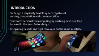
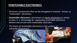
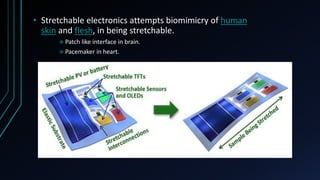
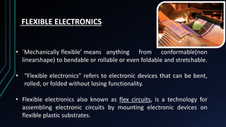
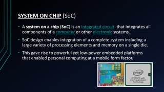
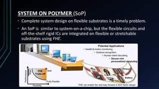
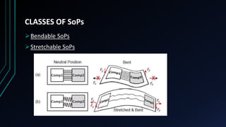
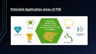
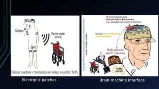
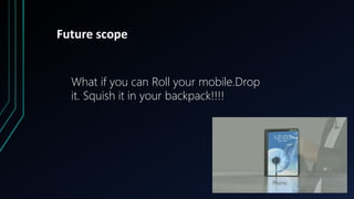
EXTENDING NETWORKS FROM CHIPS TO
STRETCHABLE AND FLEXIBLE ELECTRONICS
SURYA SHOBHAN J
S7 EC
36
GUIDED BY: JEENA MISS
Outline:
• Introduction
• Stretchable Electronics
 Manufacturing Techniques
• Flexible Electronics
 Building blocks
 Fabrication technology
 Advantages and Disadvantages
• Flexible Hybrid Electronics (FHE)
• System on Chip
• System on Polymer
• Potential Application areas of FHE
• Future scope & Conclusion
• Bibliography
INTRODUCTION
• To design a physically flexible system capable of
sensing,computation and communication.
• Transform personalized computing by enabling next step leap
forward in the form factor design.
• Integrating flexible and rigid resources on the same substrate.
STRETCHABLE ELECTRONICS
• Electronic components that can be elongated or twisted – known as
“stretchable” electronics.
• Stretchable electronics, also known as elastic electronics or elastic
circuits, is a technology for depositing stretchable electronic
devices and circuits onto stretchable substrates.
• The future of stretchable electronics is the surface, or
substrate.(Elastomers)
MANUFACTURING TECHNIQUES
1. SILICON ISLAND APPROACH
silicon wafer parts connected by flexible strips
stamped stress sustains mesh grids form
2. BUCKLING MECHANISM
Stretch the substrate attach thin film of Si on top
release the stretch stretch in all directions
• Stretchable electronics attempts biomimicry of human
skin and flesh, in being stretchable.
 Patch like interface in brain.
 Pacemaker in heart.
FLEXIBLE ELECTRONICS
• `Mechanically flexible’ means anything from conformable(non
linearshape) to bendable or rollable or even foldable and stretchable.
• “Flexible electronics” refers to electronic devices that can be bent,
rolled, or folded without losing functionality.
• Flexible electronics also known as flex circuits, is a technology for
assembling electronic circuits by mounting electronic devices on
flexible plastic substrates.
Building blocks of Flexible Electronics
Flexible electronic structure is composed of :
Substrate
Back-plane
Front-plane
Encapsulation
Substrates
• Flexible substrates must meet these requirements:
 Optical properties
 Surface roughness
 Chemical properties
 Electric properties
• 3 types of substrate materials are:
 Thin glass
 Plastic film
 Metal foil
Backplane electronics
• It is used for processing and power/signal delivery to the
frontplane.
• Materials used for backplane electronics are:
Silicon Thin-Film Transistor
Organic Thin-Film Transistor
Transparent Thin-Film Transistor
Frontplane Electronics
• Frontplanes carry the specific opto-electronic application.
• The frontplane materials of displays include:
Liquid Crystal Displays
Electrophoretic Displays
Organic Light-Emitting Displays
Actuators
Encapsulation
• To ensure long life of materials.
• Since flexible displays utilize organic materials,a barrier layer is
essential in protecting and enclosing the functional material and
layers from oxygen and degraded water.
Manufacturing of flexible electronics
For the manufacturing of flexible electronics “Roll to
Roll” (R2R) processing laser ablation and soft lithography
process is used.
Steps of R2R processing
ADVANTAGES
light weight
Smaller dimensions required
Space saving
Foldable and bendable
Wide Viewing Angle
Eco-friendly
DISADVANTAGES
Initial investment may be
expensive
Integration of components would
be challenge for engineers
Precision machines required
Performance and capabilities are
limited.
FLEXIBLE HYBRID ELECTRONICS [FHE]
• The architecture that combine flexible elements and rigid silicon to
overcome the performance limitations of purely flexible electronics.
• FHE refers to physically flexible systems that integrate commercial off-
the-shelf rigid integrated circuits (ICs) on flexible or stretchable
substrates.
• FHE can “deliver the functionality of current state-of-the-art mobile
platforms in a truly pervasive form factor.”
SYSTEM ON CHIP (SoC)
• A system on a chip (SoC) is an integrated circuit that integrates all
components of a computer or other electronic systems.
• SoC design enables integration of a complete system including a
large variety of processing elements and memory on a single die.
• This gave rise to powerful yet low-power embedded platforms
that enabled personal computing at a mobile form factor.
SYSTEM ON POLYMER (SoP)
• Complete system design on flexible substrates is a timely problem.
• An SoP is similar to system-on-a-chip, but the flexible circuits and
off-the-shelf rigid ICs are integrated on flexible or stretchable
substrates using FHE.
CLASSES OF SoPs
Bendable SoPs
Stretchable SoPs
SoP INTERCONNECT CHALLENGES AND POTENTIAL SOLUTIONS
1. Limitations of Wired Interconnects on Flexible Substrates
Bandwidth Limitations
 BW=W×fmax
Shape Changes
Reliability Limitation
2. Inter-Chip Communication over Flexible Substrate
 Wired Communication Energy
• LVDS, a low voltage, low power,differential signaling standard.
 PLVDS = Pdriver + Pchannel
 Wireless Communication Energy
 Plink,wireless = PTx + PRx
Energy-Efficiency Comparison
• wireless communication becomes more energy efficient, when the data rate
exceeds 4.1Gbps.
• a hybrid combination of wired and wireless transmission strategies can be
designed to minimize the communication energy.
Potential Application areas of FHE
Electronic patches Brain-machine interface
Future scope
What if you can Roll your mobile.Drop
it. Squish it in your backpack!!!!
CONCLUSION
• Flexible and Stretchable electronics is the Next
Big Thing!!!!
Bibliography
[1] American Semiconductor Inc. FleX
TM
Silicon-on-Polymer
http://www.americansemi.com.
[2] A. Ahmadi, O. Dehzangi, and R. Jafari, “Brain-Computer Interface
Signal Processing Algorithms: A Computational Cost Vs. Accuracy
Analysis For Wearable Computers,” in In Proc. of Intl. Conf. on
Wearable and Implantable Body Sensor Networks, 2012, pp. 40–45.
[3] American Semiconductor Inc. FleX-MCU
TM
. http://www.americansemi.com, last accessed May 2016.
[4] P. Bonato, “Wearable Sensors/Systems And Their Impact On Biomedical
Engineering,” IEEE Engineering in Medicine and Biology Magazine,
vol. 22, no. 3, pp. 18–20, 2003.
Flexible and stretchable electronics

Flexible and stretchable electronics

  • 1.
    EXTENDING NETWORKS FROMCHIPS TO STRETCHABLE AND FLEXIBLE ELECTRONICS SURYA SHOBHAN J S7 EC 36 GUIDED BY: JEENA MISS
  • 2.
    Outline: • Introduction • StretchableElectronics  Manufacturing Techniques • Flexible Electronics  Building blocks  Fabrication technology  Advantages and Disadvantages • Flexible Hybrid Electronics (FHE) • System on Chip • System on Polymer • Potential Application areas of FHE • Future scope & Conclusion • Bibliography
  • 3.
    INTRODUCTION • To designa physically flexible system capable of sensing,computation and communication. • Transform personalized computing by enabling next step leap forward in the form factor design. • Integrating flexible and rigid resources on the same substrate.
  • 4.
    STRETCHABLE ELECTRONICS • Electroniccomponents that can be elongated or twisted – known as “stretchable” electronics. • Stretchable electronics, also known as elastic electronics or elastic circuits, is a technology for depositing stretchable electronic devices and circuits onto stretchable substrates. • The future of stretchable electronics is the surface, or substrate.(Elastomers)
  • 5.
    MANUFACTURING TECHNIQUES 1. SILICONISLAND APPROACH silicon wafer parts connected by flexible strips stamped stress sustains mesh grids form
  • 6.
    2. BUCKLING MECHANISM Stretchthe substrate attach thin film of Si on top release the stretch stretch in all directions
  • 7.
    • Stretchable electronicsattempts biomimicry of human skin and flesh, in being stretchable.  Patch like interface in brain.  Pacemaker in heart.
  • 8.
    FLEXIBLE ELECTRONICS • `Mechanicallyflexible’ means anything from conformable(non linearshape) to bendable or rollable or even foldable and stretchable. • “Flexible electronics” refers to electronic devices that can be bent, rolled, or folded without losing functionality. • Flexible electronics also known as flex circuits, is a technology for assembling electronic circuits by mounting electronic devices on flexible plastic substrates.
  • 9.
    Building blocks ofFlexible Electronics Flexible electronic structure is composed of : Substrate Back-plane Front-plane Encapsulation
  • 10.
    Substrates • Flexible substratesmust meet these requirements:  Optical properties  Surface roughness  Chemical properties  Electric properties • 3 types of substrate materials are:  Thin glass  Plastic film  Metal foil
  • 11.
    Backplane electronics • Itis used for processing and power/signal delivery to the frontplane. • Materials used for backplane electronics are: Silicon Thin-Film Transistor Organic Thin-Film Transistor Transparent Thin-Film Transistor
  • 12.
    Frontplane Electronics • Frontplanescarry the specific opto-electronic application. • The frontplane materials of displays include: Liquid Crystal Displays Electrophoretic Displays Organic Light-Emitting Displays Actuators
  • 13.
    Encapsulation • To ensurelong life of materials. • Since flexible displays utilize organic materials,a barrier layer is essential in protecting and enclosing the functional material and layers from oxygen and degraded water.
  • 14.
    Manufacturing of flexibleelectronics For the manufacturing of flexible electronics “Roll to Roll” (R2R) processing laser ablation and soft lithography process is used. Steps of R2R processing
  • 15.
    ADVANTAGES light weight Smaller dimensionsrequired Space saving Foldable and bendable Wide Viewing Angle Eco-friendly DISADVANTAGES Initial investment may be expensive Integration of components would be challenge for engineers Precision machines required Performance and capabilities are limited.
  • 17.
    FLEXIBLE HYBRID ELECTRONICS[FHE] • The architecture that combine flexible elements and rigid silicon to overcome the performance limitations of purely flexible electronics. • FHE refers to physically flexible systems that integrate commercial off- the-shelf rigid integrated circuits (ICs) on flexible or stretchable substrates. • FHE can “deliver the functionality of current state-of-the-art mobile platforms in a truly pervasive form factor.”
  • 19.
    SYSTEM ON CHIP(SoC) • A system on a chip (SoC) is an integrated circuit that integrates all components of a computer or other electronic systems. • SoC design enables integration of a complete system including a large variety of processing elements and memory on a single die. • This gave rise to powerful yet low-power embedded platforms that enabled personal computing at a mobile form factor.
  • 20.
    SYSTEM ON POLYMER(SoP) • Complete system design on flexible substrates is a timely problem. • An SoP is similar to system-on-a-chip, but the flexible circuits and off-the-shelf rigid ICs are integrated on flexible or stretchable substrates using FHE.
  • 21.
    CLASSES OF SoPs BendableSoPs Stretchable SoPs
  • 22.
    SoP INTERCONNECT CHALLENGESAND POTENTIAL SOLUTIONS 1. Limitations of Wired Interconnects on Flexible Substrates Bandwidth Limitations  BW=W×fmax Shape Changes Reliability Limitation
  • 23.
    2. Inter-Chip Communicationover Flexible Substrate  Wired Communication Energy • LVDS, a low voltage, low power,differential signaling standard.  PLVDS = Pdriver + Pchannel  Wireless Communication Energy  Plink,wireless = PTx + PRx
  • 24.
    Energy-Efficiency Comparison • wirelesscommunication becomes more energy efficient, when the data rate exceeds 4.1Gbps. • a hybrid combination of wired and wireless transmission strategies can be designed to minimize the communication energy.
  • 25.
  • 26.
  • 27.
    Future scope What ifyou can Roll your mobile.Drop it. Squish it in your backpack!!!!
  • 28.
    CONCLUSION • Flexible andStretchable electronics is the Next Big Thing!!!!
  • 29.
    Bibliography [1] American SemiconductorInc. FleX TM Silicon-on-Polymer http://www.americansemi.com. [2] A. Ahmadi, O. Dehzangi, and R. Jafari, “Brain-Computer Interface Signal Processing Algorithms: A Computational Cost Vs. Accuracy Analysis For Wearable Computers,” in In Proc. of Intl. Conf. on Wearable and Implantable Body Sensor Networks, 2012, pp. 40–45. [3] American Semiconductor Inc. FleX-MCU TM . http://www.americansemi.com, last accessed May 2016. [4] P. Bonato, “Wearable Sensors/Systems And Their Impact On Biomedical Engineering,” IEEE Engineering in Medicine and Biology Magazine, vol. 22, no. 3, pp. 18–20, 2003.