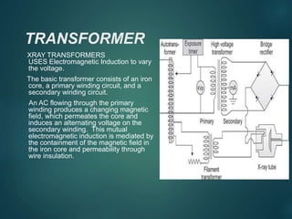
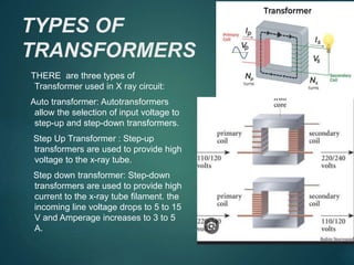
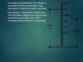
4. XRAY TUBE
ELECTRICAL DEVICE USED FOR THE GENERATION OF XRAYS
THIS IS ACOMPLISHED BY THE ACCELERATION OF ELECTRON
AND THEN SUDDENLY DECELERATING THEM
THE ENERGY OF XRAYS IS DEPENDENT ON THE KINETIC ENE
OF THE ELECTRONS
5. TRANSFORMER
XRAY TRANSFORMERS
USES Electromagnetic Induction to vary
the voltage.
The basic transformer consists of an iron
core, a primary winding circuit, and a
secondary winding circuit.
An AC flowing through the primary
winding produces a changing magnetic
field, which permeates the core and
induces an alternating voltage on the
secondary winding. This mutual
electromagnetic induction is mediated by
the containment of the magnetic field in
the iron core and permeability through
wire insulation.
6. TYPES OF
TRANSFORMERS
THERE are three types of
Transformer used in X ray circuit:
Auto transformer: Autotransformers
allow the selection of input voltage to
step-up and step-down transformers.
Step Up Transformer : Step-up
transformers are used to provide high
voltage to the x-ray tube.
Step down transformer: Step-down
transformers are used to provide high
current to the x-ray tube filament. the
incoming line voltage drops to 5 to 15
V and Amperage increases to 3 to 5
A.
7. In a step-up transformer the voltage is
increased but the amperage must
decrease to keep the power constant.
Conversely, a step-down transformer
will decrease voltage from the primary
coil to the secondary coil, with a
corresponding increase in amperage.
8. TRANFORMER EFFICIENCY
Although transformer eficiency is typically above 95%,several factors
influence how much energy is lost. Copper loss: Electric current in copp
experiences resistance that results in heat generation. Hysteresis loss:
Results from energy expended as the continually changing AC current
magnetizes, demagnetizes, and remagnetizes the core material. Eddy
currents loss: These currents oppose the magnetic field that induced the
thereby creating a loss of transformer efficiency. The current flowing thro
the coils produces heat in the transformer, which must be dissipated. X-
transformers are usually placed inside a metal box. The box is filled with
provide electrical and thermal insulation to prevent electric shock and to
the transformer.
9. RECTIFIERS
rectifiers are solid-state devices that
allow current to flow in only 1 direction.
convert high-voltage AC from the
secondary side of the step-up
transformer to high- voltage DC, which
is applied to the x-ray tube.
Current flows from + to – but in x ray
tube current flows from – to + so it best
Works with DC otherwise it may result in
no x ray production or damage to tube.
10. HALF WAVE
RECTIFICATION
Half-wave rectification uses solid-state diodes to
effectively suppress the negative portion of the
AC sine wave. The positive portion of the sine
wave is utilized to produce pulsating DC
Full-wave Rectification full-wave-rectified circuit
because the negative part of the AC sine wave is
converted to positive current. With full wave
rectification, the positive flow remains the same
but the negative portion is converted to positive
current flowing in only one direction, or DC.
This produces more uniform pulsating DC sine
wave.
11. FILAMENT
CIRCUIT
cathode is heated by current from the low voltage
supply.
Output is controlled by MA selector.
Increasing MA= More Heating Current to
Cathode=
Increased temperature= Increased thermo ionic
emission.
Two level of heating of Cathode:
1. Standby heating
2. During Exposure heating
12. EXPOSURE TIMER
Control the duration of x ray exposure. Terminater
after the preset time have elapsed or the when the
receptor have received a specific level of exposure.
Operator control switches and timers turns
radiation ON and OFF.
Of Two Types:
1. Manual Timers
2. Electronic Timer
3. Automatic Exposure control.
13. MANUAL TIMER
MANUAL Timer is shut off after machine
effectively counts in an synchronous motor. A
solenoid whose winding is in series with the
timer circuit. The core, which is magnetized
when current flows through the solenoid.
14. ELECTRONIC TIMER
ELECTRONIC TIMER Based upon the time it fully
takes to fully charge the capacitor. When
capacitor limit is reached the electricity allows
to run off from it . It is accurate and produce
the exposure time as short as 1 ms.
15. AUTOMATIC EXPOSURE CONTROL
( AEC) or Phototimer
AEC me asures the actual amount of radiation
exposure incident on IR and terminates the x ray
production when required amount is obtained.
Its components are:
radiation detectors,
an amplifier,
a film density or digital SNR variable selector,
a termination switch, and a backup timer safety
shutoff switch