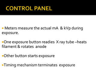
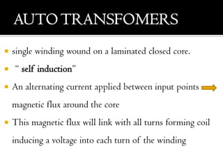
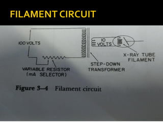
SlideShare a Scribd company logo
MUHAMMEDASLAM BS
BSC MIT
“An X ray generator is the device
that supplies electric power to the X
ray tube”
An x ray generator begins with a
source of electric energy
 Xray tube requires electrical energy
to:
i. Boil electrons from the filament
ii. Accelerate these electrons from
cathode to anode
1. main breaker - this is where the alternating current comes from to power the circuit.
2. exposure switch - when you push the button to start an exposure this switch closes to start the exposure.
3. autotransformer - this is where you adjust the kVp for the exposure.
4. timer circuit - this part of the circuit stops the exposure.
5. high-voltage step-up transformer - this transformer bumps the voltage up so that the x-ray tube has very high
voltage to make the electrons have enough energy to form x-rays.
6. four-diode rectification circuit - this makes the current only go in one direction through the x-ray tube.
7. filament circuit variable resistor - this variable resistor adjusts the current going to the filament.
8. filament step-down transformer - this transformer steps the voltage down and therefore the current up.
9. x-ray tube - this is where the x-rays are created.
10. rotor stator - this rotates the anode.
 It can be explained in two separate headings
 1)CONTROL PANELOR CONSOLE
 2)TRANSFORMERASSEMBLY
 Meters measure the actual mA & kVp during
exposure.
One exposure button readies X ray tube –heats
filament & rotates anode
Other button starts exposure
Timing mechanism terminates exposure
 TRANSFORMER - increases/decreases voltage in a
circuit
 RECTIFIER-changes alternating current to direct
current
 Grounded metal box filled with oil.
 Contains :
 low voltage transformer ;
 high voltage transformer & a group of rectifiers for the
high voltage circuit
 Oil serves as insulator
 Has 2 wire coils wrapped around a closed core
 Core- simple rectangle with windings wound around its opposite
sides
 PRIMARY CIRCUIT: connected to the available electrical
energy source
 SECONDARY CIRCUIT: from which the modified electrical
energy comes
 The core of the transformer is laminated to reduce the wastage
of power which appear as heat in the transformer core
Current flows through the
primary coil
Magnetic field is created in
the core
Magnetic field induces
current in secondary coil
1st law
The voltage in the two circuits is proportional to the
number of turns in the two coils
2nd law
A transformer cannot create energy.An increase in
voltage must be accompanied by a corresponding
decrease in current.The product of the voltage and
current in the two circuits must be equal
 single winding wound on a laminated closed core.
 “ self induction”
 An alternating current applied between input points
magnetic flux around the core
 This magnetic flux will link with all turns forming coil
inducing a voltage into each turn of the winding
 Functions:
1. Provides voltage for the X ray tube filament circuit
2. Provides voltage for the primary of the high
voltage transformer
3. Provides suitable voltage for subsidiary circuits
4. Provide a convenient location for the KVp meter
that indicates the voltage to be applied across the
x-ray tube
 Regulates current flow through filament.
 Power to heat filament is provided by small step
down transformer - Filament transformer
 The circuit has :
1. 2 transformers
2. An auto tansformer
3. A step up transformer
 Autotransformer is the kVp selector -located in the
control panel
 Voltage across primary coil of step up transformer
can be varied by selecting the appropriate number of
turns in the autotransformer
 The kVp can be adjusted in steps from
approximately 40 to 150 kVp
 It increases the voltage by a factor of approximately
600
 Potential difference across the secondary coil may
be as high as 1,50,000 V
 Hence immersed in oil in the transformer assembly
 Rectification is the process of changing
alternating current into direct current
The device that produces this change is called
RECTIFIER
 The high voltage transformer provides an alternating voltage to X
ray tube
 X ray tube connected to the secondary windings of the step up
transformer with one side of the transformer connected to
cathode and the other to the anode of the tube.
 e- flow at high speed from cathode to anode , when there is a
potential difference & produce X rays
 In next half of electrical cycle, anode is negative
& filament is positive so e- would flow from
target toward filament
 By blocking current flows in the inverse half of
the cycle, the X ray tube changes an alternating
current into direct current
 Because only half of the electrical wave is used to
produce X rays, the wave form is called HALF
WAVE RECTIFICATION
INPUTWAVE FORM FULLWAVE
RECTIFICATION
HALFWAVE
RECTIFICATION
 X ray tube itself acts as a rectifier, the circuit is
called “ SELF RECTIFIED ”.
 Disadvantages:
i. Half of the available electrical cycle is not used
to produce X rays.
ii. Due to prolonged exposures, anode gets
heated , to produce a current during the inverse
half cycle
“ A rectifier is a device that allows an electrical current
to flow in one direction but does not allow current to
flow in the other direction ”
 These are incorporated within the x ray circuit, and
same current flows through x ray tube and rectifier
 It can be vacuum-tube type or solid state composition
 The heart of a solid state rectifier is a semi conductor ,
usually a piece of crystalline silicon.
 In any atom , there are
energies between the
allowed energy levels
that are not available
for electrons to reside
in.
 When numerous atoms
together form solids,
these unallowable
energies form the
FORBIDDEN GAP.
No forbidden gap
at normal temp
and pressure
Forbidden gap is
of order of an
Electron volt
Forbidden gap is
of order 10 electron
volts
“ A material that at low temperatures acts as an
insulator but at normal room temperature acts as a
conductor ”
Semiconductors
N type
semiconductors
P type
semiconductors
 Silicon contains 4 valence electron ,
 One of the five electron of the impurity is
not utilised in the bonding called as covalent
bond
 Impurities are known as donor, since it
donates an extra electron
 Crystal resulting from the addition of the
donor is called N-type, N derived from
negative charge of the surplus electron
 Arsenic,Antimony etc..
If an impurity with 3 valence electron is added to
silicon,.
One silicon now has an electron that is looking for
another with which to form a covalent bond
Absence of this electron is called as HOLE.
Since hole is a positive particle the material is
called as a P-type semiconductor
acceptors used are Gallium,Indium,Aluminium..etc
 formed by a complex process in which P and N
materials are diffused into a single crystal.
 N-types is rich in electron and P-type is rich in holes
 Electron diffuse across the junction, N-type acquires a
net positive charge and P-type negative charge.
 This creates a DEPLETION LAYER.
 The device formed by P-N junction is called as DIODE
 If polarity of applied voltage is opposite to that
of junction, electron will flow from n-type to p-
type.
 When negative pole of a battery is connected to
N-type and positive pole to p-type, current will
flow.This is called FORWARD BIAS.
 If polarity is reversed,negative pole connected to
p-type, the junction potential will be
augmented, and no current would flow.This is
called REVERSE BIAS
DIRECTION OF
CURRENT FLOW
DIRECTION OF
ELECTRON FLOW
 When two rectifiers are connected in series with the X
ray tube
 Electrons flow through the tube from the cathode to
the anode
 When voltage reverses during the inverse half of the
cycle, the rectifier stops current flow
 This produces HALFWAVE RECTIFICATION
 Advantage is X Ray tube is protected from full
potential of the inverse cycle
 Full wave rectification employs full potential
of the electrical supply
 Both halves of the alternating voltage are
used to produce x rays
 So the X ray output per unit time is twice as
large as with half wave rectification.
 Voltage across the circuit is supplied by the
step up transformer
 In this manner 4 rectifier produce pulsating
direct current through x ray tube,even though
transformer supplied an alternating input
current
 Disadvantage is considerable portion of the
exposure time is lost.
 Commercial electric power is usually
produced and delivered by three phase
alternating current generators
 Three basic types:
1. Six pulse, six rectifer
2. Six pulse, twelve rectifier
3. Twelve pulse
 A 3 phase transformer
has 3 sets of primary
and secondary
windings
 The three sections of
copper windings in the
primary or secondary
are connected in one
of two configurations
termed delta and wye
.
DELTA
WYE OR STAR
 This design employs a delta wound primary
transformer with wye wound secondary
transformer
 Output of the secondary windings is rectified
with six solid state rectifiers
 There are three maximum and three
minimum voltages in one complete cycle
 When rectified there will be six positive
maximum voltages per cycle. Hence the term
“SIX PULSE”
“The variation in the voltage across the x ray
tube expressed as a percentage of the maximum
value”
 This circuit has a six pulse circuit with a 13.5%
theoretical ripple factor
 It has a fixed potential to ground
 Insulating requirements simplified
 Looks similar to six pulse, twelve rectifier
transformer
 Difference : the secondary is NOT a double
wye connection. It is a wye and delta
connection
 Hence, output of one winding will fill in the
ripple of the other . So a twelve pulse output
 Nearly constant potential
 Produce X rays efficiently throughout the
exposure
 Average X ray energy is higher
 Higher tube rating for extremely short X ray
exposures
“Means of supplying power for the X ray tube
independent of an external power supply”
TWOTYPES:
1. Capacitor discharge generators
2. Battery powered generators
 “a capacitor is an electrical device for storing
charge or electrons”
 110V or 220V power
 Output of high voltage transformers is
rectified and used to charge capacitor or a
bank of capacitors
 Uses a grid controlled X ray tube to start and
stop the X ray exposure
Small and easy
to move
Each exposure
starts at the
same kVp
Drop of about 1
kV for 1 mAs
Limited usage
in radiography
of thick body
parts like
abdomen
Has to be
charged
immediately
prior to use
ADVANTAGES
DISADVANTAGES
 Standard power supply is used to charge
large capacity nickel cadmium batteries
 Output from batteries is fed into a DC
chopper which interrupts the current many
times each second
 Typical value 500 times per second
Stores considerable
energy to generate X
rays
exposures independent
of a power supply
Supplies constant
output of Kv and mA
Heavy
Requires regular battery
maintenance
 Principle : “ in a transformer , the voltage
induced in the secondary coil is proportional
to the rate of change of current in the primary
coil”
 60 Hz power line frequency is converted to
6500 Hz
ADVANTAGES Supplies a constant nearly ripple
free voltage to the X ray tube
regardless of the input power
No special power supply or voltage
regulators required
Very small size
“ a switch is a device that turns the high
voltage applied to the X ray tube on and
off”
 If currents switched off rapidly,
 Energy stored in voltage system is removed
 high voltage spikes may damage the system
 If the voltage in the circuit are not removed,
the voltage across the X ray tube cannot go
to zero
SOLUTION –SWITCHING CIRCUITS
PRIMARY SWITCHING
 Switching takes place
in the primary circuit
 High currents and low
voltage
SECONDARY SWITCHING
 Switching takes place
in the secondary circuit
 Low currents and high
voltage
PRIMARY SWITCHING
 In general purpose
three phase units
SECONDARY SWITCHING
 In units designed for
rapid repetitive
exposures
 When extremely short
exposure times needed
 Angiography,
cineflurograhy
PRIMARY SWITCHING
1. Electromechanical
contractors
2. Thyatrons
3. Solid state silicon
controlled rectifiers
SECONDARY SWITCHING
1. Triode vacuum tubes
2. Grid controlled X ray
tubes
PRIMARY SWITCHING
 Easier and cheaper
 Can produce exposures
as short as 1 or 2
milliseconds
 Cannot produce
exposures at high
repetitive rate
SECONDARY SWITCHING
 Sharp crisp exposures
 Rapid on and off rates
with many repeated
exposures
Four basic types:
1. Mechanical timers
2. Electronic timers
3. Automatic exposure control
4. Pulse counting timers
The exposure button
starts exposure and also
starts charging the
capacitor
Exposure terminated
when the capacitor is
charged to a value
needed to turn on
associated electronic
currents
PRINCIPLE: The length of the X ray exposure is
determined by the time required to charge a capacitor
through a selected resistance
 They measure the amount of radiation
required to produce the correct exposure for
a radiographic examination
 Two types:
1. Entrance types: located in front of the
cassette
2. Exit types: located behind the cassette
 The essential element is a device that can
detect radiation and in response to this
radiation, produce a small current
a) Photomultiplier detectors
b) Ionization chambers
c) Solid state detectors
 Most commonly used
 Detector made of
Lucite covered with
phosphorus in areas :
Lucite Paddles
LIGHT GATE
PHOTO
MULTIPLIER
TUBE
LUCITE
PADDLE FLUORES-
CENT
SCREEN
EXPOSURE
TIMER
X RAY
GENERATOR
THANK U...

More Related Content

What's hot

"high tension generator", "high tension","tension generator", "generator", ...
"high tension generator",  "high tension","tension generator",  "generator", ..."high tension generator",  "high tension","tension generator",  "generator", ...
"high tension generator", "high tension","tension generator", "generator", ...Prem Murti
 
Filters and beam restrictors
Filters  and beam restrictorsFilters  and beam restrictors
Filters and beam restrictors
vishwanath0908
 
Portable n mobile unit
Portable n mobile unitPortable n mobile unit
Portable n mobile unitSudil Paudyal
 
Computed Radiography and digital radiography
Computed Radiography and  digital radiographyComputed Radiography and  digital radiography
Computed Radiography and digital radiography
Durga Singh
 
Grids
GridsGrids
Grids
aslam bs
 
X- Ray physics- X-Ray Tube, Transformer, Generator and Rectifiers by kajalsra...
X- Ray physics- X-Ray Tube, Transformer, Generator and Rectifiers by kajalsra...X- Ray physics- X-Ray Tube, Transformer, Generator and Rectifiers by kajalsra...
X- Ray physics- X-Ray Tube, Transformer, Generator and Rectifiers by kajalsra...
DrKajalLimbad
 
X rays generators and transformers
X rays   generators  and transformersX rays   generators  and transformers
X rays generators and transformers
shariq ahmad shah
 
Recent advancements in modern x ray tube
Recent advancements in modern x ray tubeRecent advancements in modern x ray tube
Recent advancements in modern x ray tube
Santosh Ojha
 
Interactions of X-ray & matter & Attenuation - Dr. Sayak Datta
Interactions of X-ray & matter & Attenuation - Dr. Sayak DattaInteractions of X-ray & matter & Attenuation - Dr. Sayak Datta
Interactions of X-ray & matter & Attenuation - Dr. Sayak Datta
SayakDatta
 
Ward radiography.pptx
Ward radiography.pptxWard radiography.pptx
Ward radiography.pptx
Ritupanta1
 
X ray generator, circuits
X  ray generator, circuitsX  ray generator, circuits
X ray generator, circuits
Anjan Dangal
 
Rectifiers
RectifiersRectifiers
Rectifiers
Madhu Sudana
 
X ray tube
X ray tubeX ray tube
X ray tube
Bipin Joseph
 
Mobile & portable radiography
Mobile & portable radiographyMobile & portable radiography
Mobile & portable radiography
Priyanka Parimala
 
Production of x rays & generators
Production of x rays & generatorsProduction of x rays & generators
Production of x rays & generators
Rakesh Ca
 
The control of scattered radiation
The control of scattered radiationThe control of scattered radiation
The control of scattered radiation
Nitish Rajput
 
Tomographic equipment
Tomographic equipmentTomographic equipment
Tomographic equipment
Self
 
X-RAY TUBE (ANODE)
X-RAY TUBE (ANODE)X-RAY TUBE (ANODE)
X-RAY TUBE (ANODE)
Nik Noor Ashikin Nik Ab Razak
 
CR, DR and recent advances
CR, DR and recent advancesCR, DR and recent advances
CR, DR and recent advancesVishal Sankpal
 
Computed radiography
Computed radiographyComputed radiography
Computed radiography
Anjan Dangal
 

What's hot (20)

"high tension generator", "high tension","tension generator", "generator", ...
"high tension generator",  "high tension","tension generator",  "generator", ..."high tension generator",  "high tension","tension generator",  "generator", ...
"high tension generator", "high tension","tension generator", "generator", ...
 
Filters and beam restrictors
Filters  and beam restrictorsFilters  and beam restrictors
Filters and beam restrictors
 
Portable n mobile unit
Portable n mobile unitPortable n mobile unit
Portable n mobile unit
 
Computed Radiography and digital radiography
Computed Radiography and  digital radiographyComputed Radiography and  digital radiography
Computed Radiography and digital radiography
 
Grids
GridsGrids
Grids
 
X- Ray physics- X-Ray Tube, Transformer, Generator and Rectifiers by kajalsra...
X- Ray physics- X-Ray Tube, Transformer, Generator and Rectifiers by kajalsra...X- Ray physics- X-Ray Tube, Transformer, Generator and Rectifiers by kajalsra...
X- Ray physics- X-Ray Tube, Transformer, Generator and Rectifiers by kajalsra...
 
X rays generators and transformers
X rays   generators  and transformersX rays   generators  and transformers
X rays generators and transformers
 
Recent advancements in modern x ray tube
Recent advancements in modern x ray tubeRecent advancements in modern x ray tube
Recent advancements in modern x ray tube
 
Interactions of X-ray & matter & Attenuation - Dr. Sayak Datta
Interactions of X-ray & matter & Attenuation - Dr. Sayak DattaInteractions of X-ray & matter & Attenuation - Dr. Sayak Datta
Interactions of X-ray & matter & Attenuation - Dr. Sayak Datta
 
Ward radiography.pptx
Ward radiography.pptxWard radiography.pptx
Ward radiography.pptx
 
X ray generator, circuits
X  ray generator, circuitsX  ray generator, circuits
X ray generator, circuits
 
Rectifiers
RectifiersRectifiers
Rectifiers
 
X ray tube
X ray tubeX ray tube
X ray tube
 
Mobile & portable radiography
Mobile & portable radiographyMobile & portable radiography
Mobile & portable radiography
 
Production of x rays & generators
Production of x rays & generatorsProduction of x rays & generators
Production of x rays & generators
 
The control of scattered radiation
The control of scattered radiationThe control of scattered radiation
The control of scattered radiation
 
Tomographic equipment
Tomographic equipmentTomographic equipment
Tomographic equipment
 
X-RAY TUBE (ANODE)
X-RAY TUBE (ANODE)X-RAY TUBE (ANODE)
X-RAY TUBE (ANODE)
 
CR, DR and recent advances
CR, DR and recent advancesCR, DR and recent advances
CR, DR and recent advances
 
Computed radiography
Computed radiographyComputed radiography
Computed radiography
 

Similar to X ray generator

X-ray generators..pptx
X-ray generators..pptxX-ray generators..pptx
X-ray generators..pptx
alma dsouza
 
X-Ray Generators.pptx
X-Ray Generators.pptxX-Ray Generators.pptx
X-Ray Generators.pptx
Rohit Bansal
 
Class 12 th semiconductor part 4
Class 12 th semiconductor part 4Class 12 th semiconductor part 4
Class 12 th semiconductor part 4
Priyanka Jakhar
 
Electromagnetic induction
Electromagnetic inductionElectromagnetic induction
Electromagnetic induction
naomizammit2003
 
Transformers basic electrical engineering
Transformers basic electrical engineeringTransformers basic electrical engineering
Transformers basic electrical engineering
vicky vicky
 
circuit diagram.pptx
circuit diagram.pptxcircuit diagram.pptx
circuit diagram.pptx
FAYAZ KHAWAJA
 
Transformer
TransformerTransformer
Transformer
Priyanka Jakhar
 
industrial electronics notes by Ali Azam.
industrial electronics notes by Ali Azam.industrial electronics notes by Ali Azam.
industrial electronics notes by Ali Azam.
Ali Azam
 
Electromagnetic induction
Electromagnetic inductionElectromagnetic induction
Electromagnetic induction
UgyenNamgay4
 
Transformer
TransformerTransformer
Transformer
Abhay Laxane
 
transformers electronic notes pptx in depth
transformers electronic notes pptx in depthtransformers electronic notes pptx in depth
transformers electronic notes pptx in depth
Anderson939966
 
High frequency current
High frequency current High frequency current
High frequency current
IqraButt56
 
Current Rectification.pptx
Current Rectification.pptxCurrent Rectification.pptx
Current Rectification.pptx
SaritaMahindrakar
 
Tansformer @dheeraj upadhyay
Tansformer @dheeraj upadhyayTansformer @dheeraj upadhyay
Tansformer @dheeraj upadhyay
Dheeraj Upadhyay
 
electromagnetism Exam coverage.pptx
electromagnetism Exam coverage.pptxelectromagnetism Exam coverage.pptx
electromagnetism Exam coverage.pptx
WalidHassan53
 
Full transformer
Full transformerFull transformer
Full transformer
Prateek Anandpara
 
X ray components ppt by Nitesh Chandra das
X ray components ppt by Nitesh Chandra dasX ray components ppt by Nitesh Chandra das
X ray components ppt by Nitesh Chandra das
NiteshChandraDas1
 
Transformer.pptx
Transformer.pptxTransformer.pptx
Transformer.pptx
ssuser2004c9
 
Electron Device Control
Electron Device ControlElectron Device Control
Electron Device Control
PRABHAHARAN429
 

Similar to X ray generator (20)

X-ray generators..pptx
X-ray generators..pptxX-ray generators..pptx
X-ray generators..pptx
 
X-Ray Generators.pptx
X-Ray Generators.pptxX-Ray Generators.pptx
X-Ray Generators.pptx
 
Class 12 th semiconductor part 4
Class 12 th semiconductor part 4Class 12 th semiconductor part 4
Class 12 th semiconductor part 4
 
Electromagnetic induction
Electromagnetic inductionElectromagnetic induction
Electromagnetic induction
 
Transformers basic electrical engineering
Transformers basic electrical engineeringTransformers basic electrical engineering
Transformers basic electrical engineering
 
circuit diagram.pptx
circuit diagram.pptxcircuit diagram.pptx
circuit diagram.pptx
 
Transformer
TransformerTransformer
Transformer
 
industrial electronics notes by Ali Azam.
industrial electronics notes by Ali Azam.industrial electronics notes by Ali Azam.
industrial electronics notes by Ali Azam.
 
Electromagnetic induction
Electromagnetic inductionElectromagnetic induction
Electromagnetic induction
 
Transformer
TransformerTransformer
Transformer
 
transformers electronic notes pptx in depth
transformers electronic notes pptx in depthtransformers electronic notes pptx in depth
transformers electronic notes pptx in depth
 
High frequency current
High frequency current High frequency current
High frequency current
 
Current Rectification.pptx
Current Rectification.pptxCurrent Rectification.pptx
Current Rectification.pptx
 
Tansformer @dheeraj upadhyay
Tansformer @dheeraj upadhyayTansformer @dheeraj upadhyay
Tansformer @dheeraj upadhyay
 
Theory of solids
Theory of solidsTheory of solids
Theory of solids
 
electromagnetism Exam coverage.pptx
electromagnetism Exam coverage.pptxelectromagnetism Exam coverage.pptx
electromagnetism Exam coverage.pptx
 
Full transformer
Full transformerFull transformer
Full transformer
 
X ray components ppt by Nitesh Chandra das
X ray components ppt by Nitesh Chandra dasX ray components ppt by Nitesh Chandra das
X ray components ppt by Nitesh Chandra das
 
Transformer.pptx
Transformer.pptxTransformer.pptx
Transformer.pptx
 
Electron Device Control
Electron Device ControlElectron Device Control
Electron Device Control
 

Recently uploaded

Language Across the Curriculm LAC B.Ed.
Language Across the  Curriculm LAC B.Ed.Language Across the  Curriculm LAC B.Ed.
Language Across the Curriculm LAC B.Ed.
Atul Kumar Singh
 
Home assignment II on Spectroscopy 2024 Answers.pdf
Home assignment II on Spectroscopy 2024 Answers.pdfHome assignment II on Spectroscopy 2024 Answers.pdf
Home assignment II on Spectroscopy 2024 Answers.pdf
Tamralipta Mahavidyalaya
 
The Roman Empire A Historical Colossus.pdf
The Roman Empire A Historical Colossus.pdfThe Roman Empire A Historical Colossus.pdf
The Roman Empire A Historical Colossus.pdf
kaushalkr1407
 
Basic phrases for greeting and assisting costumers
Basic phrases for greeting and assisting costumersBasic phrases for greeting and assisting costumers
Basic phrases for greeting and assisting costumers
PedroFerreira53928
 
Operation Blue Star - Saka Neela Tara
Operation Blue Star   -  Saka Neela TaraOperation Blue Star   -  Saka Neela Tara
Operation Blue Star - Saka Neela Tara
Balvir Singh
 
How to Create Map Views in the Odoo 17 ERP
How to Create Map Views in the Odoo 17 ERPHow to Create Map Views in the Odoo 17 ERP
How to Create Map Views in the Odoo 17 ERP
Celine George
 
Instructions for Submissions thorugh G- Classroom.pptx
Instructions for Submissions thorugh G- Classroom.pptxInstructions for Submissions thorugh G- Classroom.pptx
Instructions for Submissions thorugh G- Classroom.pptx
Jheel Barad
 
TESDA TM1 REVIEWER FOR NATIONAL ASSESSMENT WRITTEN AND ORAL QUESTIONS WITH A...
TESDA TM1 REVIEWER  FOR NATIONAL ASSESSMENT WRITTEN AND ORAL QUESTIONS WITH A...TESDA TM1 REVIEWER  FOR NATIONAL ASSESSMENT WRITTEN AND ORAL QUESTIONS WITH A...
TESDA TM1 REVIEWER FOR NATIONAL ASSESSMENT WRITTEN AND ORAL QUESTIONS WITH A...
EugeneSaldivar
 
Unit 8 - Information and Communication Technology (Paper I).pdf
Unit 8 - Information and Communication Technology (Paper I).pdfUnit 8 - Information and Communication Technology (Paper I).pdf
Unit 8 - Information and Communication Technology (Paper I).pdf
Thiyagu K
 
Fish and Chips - have they had their chips
Fish and Chips - have they had their chipsFish and Chips - have they had their chips
Fish and Chips - have they had their chips
GeoBlogs
 
Thesis Statement for students diagnonsed withADHD.ppt
Thesis Statement for students diagnonsed withADHD.pptThesis Statement for students diagnonsed withADHD.ppt
Thesis Statement for students diagnonsed withADHD.ppt
EverAndrsGuerraGuerr
 
The approach at University of Liverpool.pptx
The approach at University of Liverpool.pptxThe approach at University of Liverpool.pptx
The approach at University of Liverpool.pptx
Jisc
 
2024.06.01 Introducing a competency framework for languag learning materials ...
2024.06.01 Introducing a competency framework for languag learning materials ...2024.06.01 Introducing a competency framework for languag learning materials ...
2024.06.01 Introducing a competency framework for languag learning materials ...
Sandy Millin
 
Synthetic Fiber Construction in lab .pptx
Synthetic Fiber Construction in lab .pptxSynthetic Fiber Construction in lab .pptx
Synthetic Fiber Construction in lab .pptx
Pavel ( NSTU)
 
MARUTI SUZUKI- A Successful Joint Venture in India.pptx
MARUTI SUZUKI- A Successful Joint Venture in India.pptxMARUTI SUZUKI- A Successful Joint Venture in India.pptx
MARUTI SUZUKI- A Successful Joint Venture in India.pptx
bennyroshan06
 
CLASS 11 CBSE B.St Project AIDS TO TRADE - INSURANCE
CLASS 11 CBSE B.St Project AIDS TO TRADE - INSURANCECLASS 11 CBSE B.St Project AIDS TO TRADE - INSURANCE
CLASS 11 CBSE B.St Project AIDS TO TRADE - INSURANCE
BhavyaRajput3
 
Overview on Edible Vaccine: Pros & Cons with Mechanism
Overview on Edible Vaccine: Pros & Cons with MechanismOverview on Edible Vaccine: Pros & Cons with Mechanism
Overview on Edible Vaccine: Pros & Cons with Mechanism
DeeptiGupta154
 
Mule 4.6 & Java 17 Upgrade | MuleSoft Mysore Meetup #46
Mule 4.6 & Java 17 Upgrade | MuleSoft Mysore Meetup #46Mule 4.6 & Java 17 Upgrade | MuleSoft Mysore Meetup #46
Mule 4.6 & Java 17 Upgrade | MuleSoft Mysore Meetup #46
MysoreMuleSoftMeetup
 
special B.ed 2nd year old paper_20240531.pdf
special B.ed 2nd year old paper_20240531.pdfspecial B.ed 2nd year old paper_20240531.pdf
special B.ed 2nd year old paper_20240531.pdf
Special education needs
 
How libraries can support authors with open access requirements for UKRI fund...
How libraries can support authors with open access requirements for UKRI fund...How libraries can support authors with open access requirements for UKRI fund...
How libraries can support authors with open access requirements for UKRI fund...
Jisc
 

Recently uploaded (20)

Language Across the Curriculm LAC B.Ed.
Language Across the  Curriculm LAC B.Ed.Language Across the  Curriculm LAC B.Ed.
Language Across the Curriculm LAC B.Ed.
 
Home assignment II on Spectroscopy 2024 Answers.pdf
Home assignment II on Spectroscopy 2024 Answers.pdfHome assignment II on Spectroscopy 2024 Answers.pdf
Home assignment II on Spectroscopy 2024 Answers.pdf
 
The Roman Empire A Historical Colossus.pdf
The Roman Empire A Historical Colossus.pdfThe Roman Empire A Historical Colossus.pdf
The Roman Empire A Historical Colossus.pdf
 
Basic phrases for greeting and assisting costumers
Basic phrases for greeting and assisting costumersBasic phrases for greeting and assisting costumers
Basic phrases for greeting and assisting costumers
 
Operation Blue Star - Saka Neela Tara
Operation Blue Star   -  Saka Neela TaraOperation Blue Star   -  Saka Neela Tara
Operation Blue Star - Saka Neela Tara
 
How to Create Map Views in the Odoo 17 ERP
How to Create Map Views in the Odoo 17 ERPHow to Create Map Views in the Odoo 17 ERP
How to Create Map Views in the Odoo 17 ERP
 
Instructions for Submissions thorugh G- Classroom.pptx
Instructions for Submissions thorugh G- Classroom.pptxInstructions for Submissions thorugh G- Classroom.pptx
Instructions for Submissions thorugh G- Classroom.pptx
 
TESDA TM1 REVIEWER FOR NATIONAL ASSESSMENT WRITTEN AND ORAL QUESTIONS WITH A...
TESDA TM1 REVIEWER  FOR NATIONAL ASSESSMENT WRITTEN AND ORAL QUESTIONS WITH A...TESDA TM1 REVIEWER  FOR NATIONAL ASSESSMENT WRITTEN AND ORAL QUESTIONS WITH A...
TESDA TM1 REVIEWER FOR NATIONAL ASSESSMENT WRITTEN AND ORAL QUESTIONS WITH A...
 
Unit 8 - Information and Communication Technology (Paper I).pdf
Unit 8 - Information and Communication Technology (Paper I).pdfUnit 8 - Information and Communication Technology (Paper I).pdf
Unit 8 - Information and Communication Technology (Paper I).pdf
 
Fish and Chips - have they had their chips
Fish and Chips - have they had their chipsFish and Chips - have they had their chips
Fish and Chips - have they had their chips
 
Thesis Statement for students diagnonsed withADHD.ppt
Thesis Statement for students diagnonsed withADHD.pptThesis Statement for students diagnonsed withADHD.ppt
Thesis Statement for students diagnonsed withADHD.ppt
 
The approach at University of Liverpool.pptx
The approach at University of Liverpool.pptxThe approach at University of Liverpool.pptx
The approach at University of Liverpool.pptx
 
2024.06.01 Introducing a competency framework for languag learning materials ...
2024.06.01 Introducing a competency framework for languag learning materials ...2024.06.01 Introducing a competency framework for languag learning materials ...
2024.06.01 Introducing a competency framework for languag learning materials ...
 
Synthetic Fiber Construction in lab .pptx
Synthetic Fiber Construction in lab .pptxSynthetic Fiber Construction in lab .pptx
Synthetic Fiber Construction in lab .pptx
 
MARUTI SUZUKI- A Successful Joint Venture in India.pptx
MARUTI SUZUKI- A Successful Joint Venture in India.pptxMARUTI SUZUKI- A Successful Joint Venture in India.pptx
MARUTI SUZUKI- A Successful Joint Venture in India.pptx
 
CLASS 11 CBSE B.St Project AIDS TO TRADE - INSURANCE
CLASS 11 CBSE B.St Project AIDS TO TRADE - INSURANCECLASS 11 CBSE B.St Project AIDS TO TRADE - INSURANCE
CLASS 11 CBSE B.St Project AIDS TO TRADE - INSURANCE
 
Overview on Edible Vaccine: Pros & Cons with Mechanism
Overview on Edible Vaccine: Pros & Cons with MechanismOverview on Edible Vaccine: Pros & Cons with Mechanism
Overview on Edible Vaccine: Pros & Cons with Mechanism
 
Mule 4.6 & Java 17 Upgrade | MuleSoft Mysore Meetup #46
Mule 4.6 & Java 17 Upgrade | MuleSoft Mysore Meetup #46Mule 4.6 & Java 17 Upgrade | MuleSoft Mysore Meetup #46
Mule 4.6 & Java 17 Upgrade | MuleSoft Mysore Meetup #46
 
special B.ed 2nd year old paper_20240531.pdf
special B.ed 2nd year old paper_20240531.pdfspecial B.ed 2nd year old paper_20240531.pdf
special B.ed 2nd year old paper_20240531.pdf
 
How libraries can support authors with open access requirements for UKRI fund...
How libraries can support authors with open access requirements for UKRI fund...How libraries can support authors with open access requirements for UKRI fund...
How libraries can support authors with open access requirements for UKRI fund...
 

X ray generator

  • 2. “An X ray generator is the device that supplies electric power to the X ray tube” An x ray generator begins with a source of electric energy
  • 3.  Xray tube requires electrical energy to: i. Boil electrons from the filament ii. Accelerate these electrons from cathode to anode
  • 4. 1. main breaker - this is where the alternating current comes from to power the circuit. 2. exposure switch - when you push the button to start an exposure this switch closes to start the exposure. 3. autotransformer - this is where you adjust the kVp for the exposure. 4. timer circuit - this part of the circuit stops the exposure. 5. high-voltage step-up transformer - this transformer bumps the voltage up so that the x-ray tube has very high voltage to make the electrons have enough energy to form x-rays. 6. four-diode rectification circuit - this makes the current only go in one direction through the x-ray tube. 7. filament circuit variable resistor - this variable resistor adjusts the current going to the filament. 8. filament step-down transformer - this transformer steps the voltage down and therefore the current up. 9. x-ray tube - this is where the x-rays are created. 10. rotor stator - this rotates the anode.
  • 5.  It can be explained in two separate headings  1)CONTROL PANELOR CONSOLE  2)TRANSFORMERASSEMBLY
  • 6.  Meters measure the actual mA & kVp during exposure. One exposure button readies X ray tube –heats filament & rotates anode Other button starts exposure Timing mechanism terminates exposure
  • 7.  TRANSFORMER - increases/decreases voltage in a circuit  RECTIFIER-changes alternating current to direct current
  • 8.  Grounded metal box filled with oil.  Contains :  low voltage transformer ;  high voltage transformer & a group of rectifiers for the high voltage circuit  Oil serves as insulator
  • 9.  Has 2 wire coils wrapped around a closed core  Core- simple rectangle with windings wound around its opposite sides  PRIMARY CIRCUIT: connected to the available electrical energy source  SECONDARY CIRCUIT: from which the modified electrical energy comes  The core of the transformer is laminated to reduce the wastage of power which appear as heat in the transformer core
  • 10. Current flows through the primary coil Magnetic field is created in the core Magnetic field induces current in secondary coil
  • 11. 1st law The voltage in the two circuits is proportional to the number of turns in the two coils
  • 12. 2nd law A transformer cannot create energy.An increase in voltage must be accompanied by a corresponding decrease in current.The product of the voltage and current in the two circuits must be equal
  • 13.  single winding wound on a laminated closed core.  “ self induction”  An alternating current applied between input points magnetic flux around the core  This magnetic flux will link with all turns forming coil inducing a voltage into each turn of the winding
  • 14.  Functions: 1. Provides voltage for the X ray tube filament circuit 2. Provides voltage for the primary of the high voltage transformer 3. Provides suitable voltage for subsidiary circuits 4. Provide a convenient location for the KVp meter that indicates the voltage to be applied across the x-ray tube
  • 15.  Regulates current flow through filament.  Power to heat filament is provided by small step down transformer - Filament transformer
  • 16.
  • 17.  The circuit has : 1. 2 transformers 2. An auto tansformer 3. A step up transformer
  • 18.  Autotransformer is the kVp selector -located in the control panel  Voltage across primary coil of step up transformer can be varied by selecting the appropriate number of turns in the autotransformer  The kVp can be adjusted in steps from approximately 40 to 150 kVp
  • 19.  It increases the voltage by a factor of approximately 600  Potential difference across the secondary coil may be as high as 1,50,000 V  Hence immersed in oil in the transformer assembly
  • 20.
  • 21.  Rectification is the process of changing alternating current into direct current The device that produces this change is called RECTIFIER
  • 22.  The high voltage transformer provides an alternating voltage to X ray tube  X ray tube connected to the secondary windings of the step up transformer with one side of the transformer connected to cathode and the other to the anode of the tube.  e- flow at high speed from cathode to anode , when there is a potential difference & produce X rays
  • 23.  In next half of electrical cycle, anode is negative & filament is positive so e- would flow from target toward filament  By blocking current flows in the inverse half of the cycle, the X ray tube changes an alternating current into direct current
  • 24.  Because only half of the electrical wave is used to produce X rays, the wave form is called HALF WAVE RECTIFICATION INPUTWAVE FORM FULLWAVE RECTIFICATION HALFWAVE RECTIFICATION
  • 25.  X ray tube itself acts as a rectifier, the circuit is called “ SELF RECTIFIED ”.  Disadvantages: i. Half of the available electrical cycle is not used to produce X rays. ii. Due to prolonged exposures, anode gets heated , to produce a current during the inverse half cycle
  • 26. “ A rectifier is a device that allows an electrical current to flow in one direction but does not allow current to flow in the other direction ”  These are incorporated within the x ray circuit, and same current flows through x ray tube and rectifier  It can be vacuum-tube type or solid state composition  The heart of a solid state rectifier is a semi conductor , usually a piece of crystalline silicon.
  • 27.  In any atom , there are energies between the allowed energy levels that are not available for electrons to reside in.  When numerous atoms together form solids, these unallowable energies form the FORBIDDEN GAP.
  • 28. No forbidden gap at normal temp and pressure Forbidden gap is of order of an Electron volt Forbidden gap is of order 10 electron volts
  • 29. “ A material that at low temperatures acts as an insulator but at normal room temperature acts as a conductor ” Semiconductors N type semiconductors P type semiconductors
  • 30.  Silicon contains 4 valence electron ,  One of the five electron of the impurity is not utilised in the bonding called as covalent bond  Impurities are known as donor, since it donates an extra electron  Crystal resulting from the addition of the donor is called N-type, N derived from negative charge of the surplus electron  Arsenic,Antimony etc..
  • 31. If an impurity with 3 valence electron is added to silicon,. One silicon now has an electron that is looking for another with which to form a covalent bond Absence of this electron is called as HOLE. Since hole is a positive particle the material is called as a P-type semiconductor acceptors used are Gallium,Indium,Aluminium..etc
  • 32.
  • 33.  formed by a complex process in which P and N materials are diffused into a single crystal.  N-types is rich in electron and P-type is rich in holes  Electron diffuse across the junction, N-type acquires a net positive charge and P-type negative charge.  This creates a DEPLETION LAYER.  The device formed by P-N junction is called as DIODE
  • 34.
  • 35.  If polarity of applied voltage is opposite to that of junction, electron will flow from n-type to p- type.  When negative pole of a battery is connected to N-type and positive pole to p-type, current will flow.This is called FORWARD BIAS.  If polarity is reversed,negative pole connected to p-type, the junction potential will be augmented, and no current would flow.This is called REVERSE BIAS
  • 36.
  • 38.  When two rectifiers are connected in series with the X ray tube  Electrons flow through the tube from the cathode to the anode  When voltage reverses during the inverse half of the cycle, the rectifier stops current flow  This produces HALFWAVE RECTIFICATION  Advantage is X Ray tube is protected from full potential of the inverse cycle
  • 39.  Full wave rectification employs full potential of the electrical supply  Both halves of the alternating voltage are used to produce x rays  So the X ray output per unit time is twice as large as with half wave rectification.  Voltage across the circuit is supplied by the step up transformer
  • 40.
  • 41.  In this manner 4 rectifier produce pulsating direct current through x ray tube,even though transformer supplied an alternating input current  Disadvantage is considerable portion of the exposure time is lost.
  • 42.  Commercial electric power is usually produced and delivered by three phase alternating current generators  Three basic types: 1. Six pulse, six rectifer 2. Six pulse, twelve rectifier 3. Twelve pulse
  • 43.  A 3 phase transformer has 3 sets of primary and secondary windings  The three sections of copper windings in the primary or secondary are connected in one of two configurations termed delta and wye . DELTA WYE OR STAR
  • 44.
  • 45.  This design employs a delta wound primary transformer with wye wound secondary transformer  Output of the secondary windings is rectified with six solid state rectifiers
  • 46.  There are three maximum and three minimum voltages in one complete cycle  When rectified there will be six positive maximum voltages per cycle. Hence the term “SIX PULSE”
  • 47. “The variation in the voltage across the x ray tube expressed as a percentage of the maximum value”
  • 48.
  • 49.  This circuit has a six pulse circuit with a 13.5% theoretical ripple factor  It has a fixed potential to ground  Insulating requirements simplified
  • 50.  Looks similar to six pulse, twelve rectifier transformer  Difference : the secondary is NOT a double wye connection. It is a wye and delta connection  Hence, output of one winding will fill in the ripple of the other . So a twelve pulse output
  • 51.  Nearly constant potential  Produce X rays efficiently throughout the exposure  Average X ray energy is higher  Higher tube rating for extremely short X ray exposures
  • 52. “Means of supplying power for the X ray tube independent of an external power supply” TWOTYPES: 1. Capacitor discharge generators 2. Battery powered generators
  • 53.  “a capacitor is an electrical device for storing charge or electrons”  110V or 220V power  Output of high voltage transformers is rectified and used to charge capacitor or a bank of capacitors  Uses a grid controlled X ray tube to start and stop the X ray exposure
  • 54. Small and easy to move Each exposure starts at the same kVp Drop of about 1 kV for 1 mAs Limited usage in radiography of thick body parts like abdomen Has to be charged immediately prior to use ADVANTAGES DISADVANTAGES
  • 55.  Standard power supply is used to charge large capacity nickel cadmium batteries  Output from batteries is fed into a DC chopper which interrupts the current many times each second  Typical value 500 times per second
  • 56. Stores considerable energy to generate X rays exposures independent of a power supply Supplies constant output of Kv and mA Heavy Requires regular battery maintenance
  • 57.  Principle : “ in a transformer , the voltage induced in the secondary coil is proportional to the rate of change of current in the primary coil”  60 Hz power line frequency is converted to 6500 Hz
  • 58. ADVANTAGES Supplies a constant nearly ripple free voltage to the X ray tube regardless of the input power No special power supply or voltage regulators required Very small size
  • 59. “ a switch is a device that turns the high voltage applied to the X ray tube on and off”
  • 60.  If currents switched off rapidly,  Energy stored in voltage system is removed  high voltage spikes may damage the system  If the voltage in the circuit are not removed, the voltage across the X ray tube cannot go to zero SOLUTION –SWITCHING CIRCUITS
  • 61. PRIMARY SWITCHING  Switching takes place in the primary circuit  High currents and low voltage SECONDARY SWITCHING  Switching takes place in the secondary circuit  Low currents and high voltage
  • 62. PRIMARY SWITCHING  In general purpose three phase units SECONDARY SWITCHING  In units designed for rapid repetitive exposures  When extremely short exposure times needed  Angiography, cineflurograhy
  • 63. PRIMARY SWITCHING 1. Electromechanical contractors 2. Thyatrons 3. Solid state silicon controlled rectifiers SECONDARY SWITCHING 1. Triode vacuum tubes 2. Grid controlled X ray tubes
  • 64. PRIMARY SWITCHING  Easier and cheaper  Can produce exposures as short as 1 or 2 milliseconds  Cannot produce exposures at high repetitive rate SECONDARY SWITCHING  Sharp crisp exposures  Rapid on and off rates with many repeated exposures
  • 65. Four basic types: 1. Mechanical timers 2. Electronic timers 3. Automatic exposure control 4. Pulse counting timers
  • 66. The exposure button starts exposure and also starts charging the capacitor Exposure terminated when the capacitor is charged to a value needed to turn on associated electronic currents PRINCIPLE: The length of the X ray exposure is determined by the time required to charge a capacitor through a selected resistance
  • 67.  They measure the amount of radiation required to produce the correct exposure for a radiographic examination  Two types: 1. Entrance types: located in front of the cassette 2. Exit types: located behind the cassette
  • 68.  The essential element is a device that can detect radiation and in response to this radiation, produce a small current a) Photomultiplier detectors b) Ionization chambers c) Solid state detectors
  • 69.  Most commonly used  Detector made of Lucite covered with phosphorus in areas : Lucite Paddles LIGHT GATE PHOTO MULTIPLIER TUBE LUCITE PADDLE FLUORES- CENT SCREEN EXPOSURE TIMER X RAY GENERATOR