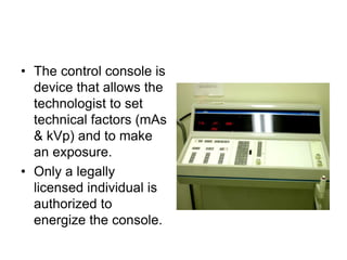
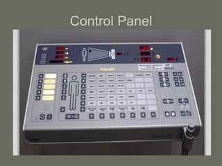
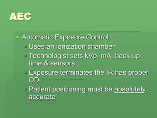
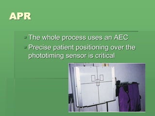
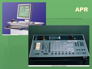
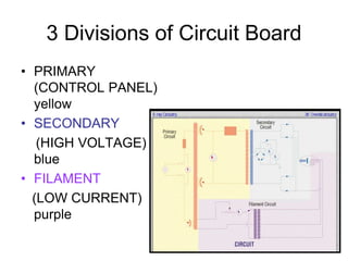
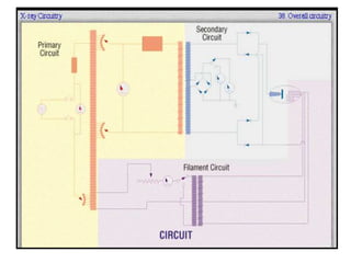
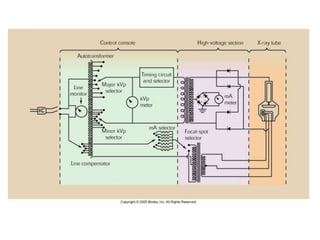
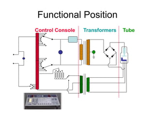
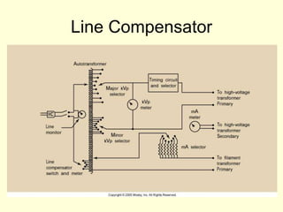
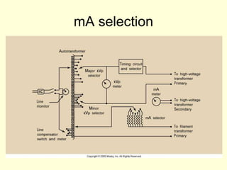
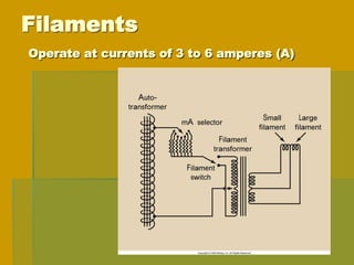
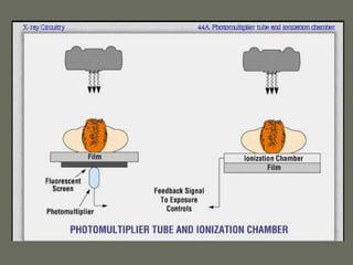
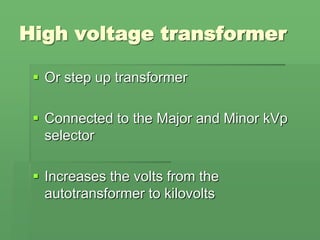
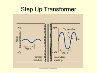
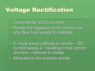
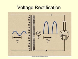
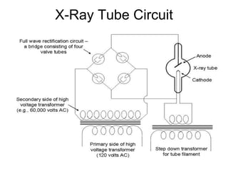
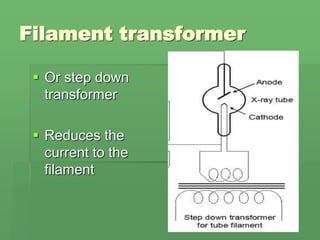
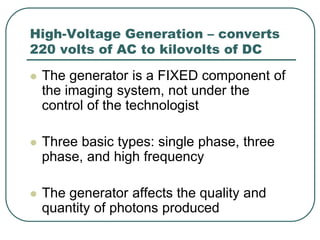
SlideShare a Scribd company logo
The X-ray Imaging
System
Week 4-5
Bucky slot cover
 During fluoroscopy the Bucky tray is
moved to the end of the table
 This leaves an opening in the side of the
table about 5cm
 Approximately at what level is the bucky?
Bucky slot cover
• The opening should
automatically be
covered with at least
0.25 mm Pb equiv..
Fluoroscopy
The Control Console
• The control console is
device that allows the
technologist to set
technical factors (mAs
& kVp) and to make
an exposure.
• Only a legally
licensed individual is
authorized to
energize the console.
Control Panel
• All the electric circuits connecting the meters
and controls are at low voltage to minimize the
possibility of shock.
Operating Console
Controls:
 Line Compensation, kVp, mA and time
 Quantity = # of x-rays
 Milliroentges (mR) or (mR/mAs)
 Quality = the pentrability
 Kilovolts peak (kVp)
Operating Console has
meters to measure
 kVp, mA, & exposure time
 Modern units only display mAs
 Units with ACE’s will have a separate
meter for mAs
Control Panel
AEC
 Automatic Exposure Control
 Uses an ionization chamber
 Technologist sets kVp, mA, back-up
time & sensors
 Exposure terminates the IR has proper
OD
 Patient positioning must be absolutely
accurate
AEC
Sensors
APR
 Anatomically Programmed Radiography
(Ch 15)
 Radiologic Technologist selects on the
console a picture or a written
description of the anatomic part to be
imaged and the patient body habitus
 A computer selects the appropriate
kVp and mAs.
APR
 The whole process uses an AEC
 Precise patient positioning over the
phototiming sensor is critical
APR
X-RAY CIRCUITY
Contributions by Mosby, Thompson Publisher, Carlton, Bushberg, and the WWW.
3 Divisions of Circuit Board
• PRIMARY
(CONTROL PANEL)
yellow
• SECONDARY
(HIGH VOLTAGE)
blue
• FILAMENT
(LOW CURRENT)
purple
Functional Position
Control Console Transformers Tube
Line Compensation
 Most imaging systems are designed to operate
on 220 V. (some 110 V or 440 V)
 However power from the wall is not always
accurate continuously
Line Compensation
 Wired to the autotransformer is the line
compensator
 Designed to maintain the accurate
voltage required for consistent production
of high-quality images
 Today’s line compensators are automatic
and are not displayed on the control panel
Line Compensator
Autotransformer
 The power for the x-ray imaging system
is delivered first to the autotransformer
 The autotransformer works on the
principle of electromagnetic induction
 It has one winding and one core
 There are a number of connections along
its length
Autotransformer
• A’s = primary
connections &
power into the
transformer
• Other connections
allow for variations
of voltages
Autotransformer
 Is designed to step up voltage to about
twice the input voltage value
 The increase in voltage is directly related
to the number of turns
kVp selection
X-ray tube current or
Filament circuit
 A separate circuit crossing from cathode
to anode
 Measured in milliampers (mA)
 What determines how many x-rays are
created?
X-ray tube current or
Filament circuit
 # of e- is determined by the temperature
of the filament. The hotter the filament
the more e-
 Are their any limiting factors to thermionic
emission?
mA selection
Filaments
Operate at currents of 3 to 6 amperes (A)
Question?
What is directly proportional to
the number of x-rays reaching
the IR?
Exposure Timers
 The timer circuit is separate from the other
main circuits of the imaging system
 It is a mechanical or electronic device
whose action is to “make” and “break” the
high voltage across the x-ray tube
 This is done on the primary side of the high
voltage transformer.
mAs Timers
 Monitors the product of mA and exposure
time
 Terminates the exposure when the
desired mAs value is reached
 Located on the secondary side of the
high-voltage transformer since actual
tube current must be monitored
mAs Timers
 Designed to proved the highest mA for
the shortest exposure
 Modern X-ray machines have falling-load
generator
 Automatically adjusts to the highest mA at
the shortest exposure time possible
AEC Control
 AEC measure the quantity of radiation
reaching the IR
 Automatically terminates when the IR has
received enough radiation for desired OD
 Two types are common
Flat, parallel plate
ionization chamber
 Located between the patient and the IR
 Made radiolucent
 Ionization w/in the chamber creates a
charge; calibrated to produce a given OD
on the IR
Photomultiplier (Photodiode)
detector assembly
 Located behind the IR
 Contains a fluorescent screen and a
photomultiplier
 The photomultiplier detects the light from
the fluorescent screen until the desired
OD on the IR is reached terminating the
exposure
AEC’s
 Upon instillation must be calibrated by
the service engineer
 Technologists selects the desired OD
which then sets the mA & kVp
AEC’s
 A back up timer usually automatically set
to prevent over exposure if the AEC fails
 Should be set to 1.5 times the expected
exposure time Why?
 When the ionization chamber or
photodiode reaches the preset level, a
signal is returned to the operating
console to terminate the exposure
High-Voltage Generator
 Responsible for increasing the output
voltage from the autotransformer to the
kVp necessary for x-ray production
 3 parts: High-voltage transformer (step-
up), filament transformer (step-down) and
rectifiers
High voltage transformer
 Or step up transformer
 Connected to the Major and Minor kVp
selector
 Increases the volts from the
autotransformer to kilovolts
Step Up Transformer
Voltage Rectification
 Converts AC to DC current
 During the negative cycle current can
only flow from anode to cathode
 E- must travel cathode to anode – DC
current keeps e- traveling in the correct
direction, cathode to anode
 Attracted to the positive anode
Voltage Rectification
X-Ray Tube Circuit
Filament transformer
 Or step down
transformer
 Reduces the
current to the
filament
High-Voltage Generation – converts
220 volts of AC to kilovolts of DC
 The generator is a FIXED component of
the imaging system, not under the
control of the technologist
 Three basic types: single phase, three
phase, and high frequency
 The generator affects the quality and
quantity of photons produced
How does this effect technique
selection?
Questions on imaging systems?

More Related Content

What's hot

Attenuation
AttenuationAttenuation
Attenuation
Archana Koshy
 
X ray generator, circuits
X  ray generator, circuitsX  ray generator, circuits
X ray generator, circuits
Anjan Dangal
 
Radiographic factor
Radiographic factorRadiographic factor
Radiographic factor
Dr,saket Jain
 
Faults in x ray tube and its care
Faults in x ray tube and its careFaults in x ray tube and its care
Faults in x ray tube and its care
SaruGosain
 
Rectifiers
RectifiersRectifiers
Rectifiers
Madhu Sudana
 
X ray production & emission
X ray production & emissionX ray production & emission
X ray production & emissionairwave12
 
Line focus-principle-and-anode-heel-effect
Line focus-principle-and-anode-heel-effectLine focus-principle-and-anode-heel-effect
Line focus-principle-and-anode-heel-effect
JoaquinLuisRinehart1
 
Sensitometer
SensitometerSensitometer
Sensitometer
Deepaknegi09
 
Exposure factors2
Exposure factors2Exposure factors2
Exposure factors2mr_koky
 
L12 Shielding
L12 ShieldingL12 Shielding
L12 Shieldinglidgor
 
The x ray tube
The x ray tubeThe x ray tube
The x ray tubeairwave12
 
Radiographic exposure and image quality
Radiographic exposure and image qualityRadiographic exposure and image quality
Radiographic exposure and image qualityRad Tech
 
Radiation protection
Radiation protectionRadiation protection
Radiation protectionjyotimannath
 
ATTENUATION AND FILTERS.pptx
ATTENUATION AND FILTERS.pptxATTENUATION AND FILTERS.pptx
ATTENUATION AND FILTERS.pptx
dypradio
 
Beam restricted device and filter used in x ray
Beam restricted device and filter used in x rayBeam restricted device and filter used in x ray
Beam restricted device and filter used in x ray
SushilPattar
 
X-Ray Generator
X-Ray GeneratorX-Ray Generator
X-Ray Generator
NISHANT RAJ
 
Anode heel effect, line focus principle,
Anode heel effect, line focus principle,Anode heel effect, line focus principle,
Anode heel effect, line focus principle,
InosRagan
 
Viewing and recording the fluoroscopic image
Viewing and recording the fluoroscopic imageViewing and recording the fluoroscopic image
Viewing and recording the fluoroscopic image
SHASHI BHUSHAN
 
Fluoroscopy-Rohit.pptx
Fluoroscopy-Rohit.pptxFluoroscopy-Rohit.pptx
Fluoroscopy-Rohit.pptx
Rohit Bansal
 
Radiation units
Radiation unitsRadiation units
Radiation units
Dr Vijay Raturi
 

What's hot (20)

Attenuation
AttenuationAttenuation
Attenuation
 
X ray generator, circuits
X  ray generator, circuitsX  ray generator, circuits
X ray generator, circuits
 
Radiographic factor
Radiographic factorRadiographic factor
Radiographic factor
 
Faults in x ray tube and its care
Faults in x ray tube and its careFaults in x ray tube and its care
Faults in x ray tube and its care
 
Rectifiers
RectifiersRectifiers
Rectifiers
 
X ray production & emission
X ray production & emissionX ray production & emission
X ray production & emission
 
Line focus-principle-and-anode-heel-effect
Line focus-principle-and-anode-heel-effectLine focus-principle-and-anode-heel-effect
Line focus-principle-and-anode-heel-effect
 
Sensitometer
SensitometerSensitometer
Sensitometer
 
Exposure factors2
Exposure factors2Exposure factors2
Exposure factors2
 
L12 Shielding
L12 ShieldingL12 Shielding
L12 Shielding
 
The x ray tube
The x ray tubeThe x ray tube
The x ray tube
 
Radiographic exposure and image quality
Radiographic exposure and image qualityRadiographic exposure and image quality
Radiographic exposure and image quality
 
Radiation protection
Radiation protectionRadiation protection
Radiation protection
 
ATTENUATION AND FILTERS.pptx
ATTENUATION AND FILTERS.pptxATTENUATION AND FILTERS.pptx
ATTENUATION AND FILTERS.pptx
 
Beam restricted device and filter used in x ray
Beam restricted device and filter used in x rayBeam restricted device and filter used in x ray
Beam restricted device and filter used in x ray
 
X-Ray Generator
X-Ray GeneratorX-Ray Generator
X-Ray Generator
 
Anode heel effect, line focus principle,
Anode heel effect, line focus principle,Anode heel effect, line focus principle,
Anode heel effect, line focus principle,
 
Viewing and recording the fluoroscopic image
Viewing and recording the fluoroscopic imageViewing and recording the fluoroscopic image
Viewing and recording the fluoroscopic image
 
Fluoroscopy-Rohit.pptx
Fluoroscopy-Rohit.pptxFluoroscopy-Rohit.pptx
Fluoroscopy-Rohit.pptx
 
Radiation units
Radiation unitsRadiation units
Radiation units
 

Similar to X RAY IMAGING.ppt

The x ray imaging system
The x ray imaging systemThe x ray imaging system
The x ray imaging systemRad Tech
 
Control of kV and mA in x-ray tube.pptx
Control of kV and mA in x-ray tube.pptxControl of kV and mA in x-ray tube.pptx
Control of kV and mA in x-ray tube.pptx
Sagar Chaulagain
 
Ac Power Problems And Measurement Sreevidhya@Students
Ac Power Problems And Measurement Sreevidhya@StudentsAc Power Problems And Measurement Sreevidhya@Students
Ac Power Problems And Measurement Sreevidhya@StudentsB Bhargav Reddy
 
X-RAY GENERATORS(1).pdf
X-RAY GENERATORS(1).pdfX-RAY GENERATORS(1).pdf
X-RAY GENERATORS(1).pdf
PrincePrajapati20
 
X ray generator new.ppt
X ray generator new.pptX ray generator new.ppt
X ray generator new.ppt
jayapandiyan Paraman
 
Power Distribution Report of THE NEOTIA UNIVERSITY CAMPUS
Power Distribution Report of  THE NEOTIA UNIVERSITY CAMPUSPower Distribution Report of  THE NEOTIA UNIVERSITY CAMPUS
Power Distribution Report of THE NEOTIA UNIVERSITY CAMPUS
Saikat Bhandari
 
12-Rietveld-Transformer-load-loss-measurement.pdf
12-Rietveld-Transformer-load-loss-measurement.pdf12-Rietveld-Transformer-load-loss-measurement.pdf
12-Rietveld-Transformer-load-loss-measurement.pdf
RafikCherni
 
Distribu pQ.pptx
Distribu pQ.pptxDistribu pQ.pptx
Distribu pQ.pptx
bhuvana71
 
4_INFRARED REMOTE USED FOR 8
4_INFRARED REMOTE USED FOR 84_INFRARED REMOTE USED FOR 8
4_INFRARED REMOTE USED FOR 8SURAJ MAHAPATRA
 
Voltmeter
VoltmeterVoltmeter
Voltmeter
vaibhav jindal
 
X-ray generators.pptx
X-ray generators.pptxX-ray generators.pptx
X-ray generators.pptx
FatimaSBEITY1
 
Webinar Slides: Measurements and Analysis for Switched-mode Power Designs
Webinar Slides: Measurements and Analysis for Switched-mode Power DesignsWebinar Slides: Measurements and Analysis for Switched-mode Power Designs
Webinar Slides: Measurements and Analysis for Switched-mode Power Designs
teledynelecroy
 
x ray machine ppt
x ray machine pptx ray machine ppt
x ray machine ppt
hunde7
 
ACD-instrumentation amplifier & peaking amplifier
ACD-instrumentation amplifier & peaking amplifier  ACD-instrumentation amplifier & peaking amplifier
ACD-instrumentation amplifier & peaking amplifier
Ðîgëñ Tàìlør
 
132kV GSS ppt
132kV GSS ppt132kV GSS ppt
132kV GSS ppt
Abhishek Dosaya
 
Am transmitter
Am transmitterAm transmitter
Am transmitter
Pradeep Singh Yadav
 
AC-AC voltage covertors (Cycloconvertors)
AC-AC voltage covertors (Cycloconvertors)AC-AC voltage covertors (Cycloconvertors)
AC-AC voltage covertors (Cycloconvertors)
Taimur Ijaz
 
Instrumentation amplifier in ECG
Instrumentation amplifier  in ECG Instrumentation amplifier  in ECG
Instrumentation amplifier in ECG
Keerthana Chithanathan
 
Output power meter
Output power meterOutput power meter
Output power meter
ajeet singh
 

Similar to X RAY IMAGING.ppt (20)

The x ray imaging system
The x ray imaging systemThe x ray imaging system
The x ray imaging system
 
Control of kV and mA in x-ray tube.pptx
Control of kV and mA in x-ray tube.pptxControl of kV and mA in x-ray tube.pptx
Control of kV and mA in x-ray tube.pptx
 
Ac Power Problems And Measurement Sreevidhya@Students
Ac Power Problems And Measurement Sreevidhya@StudentsAc Power Problems And Measurement Sreevidhya@Students
Ac Power Problems And Measurement Sreevidhya@Students
 
X-RAY GENERATORS(1).pdf
X-RAY GENERATORS(1).pdfX-RAY GENERATORS(1).pdf
X-RAY GENERATORS(1).pdf
 
X ray generator new.ppt
X ray generator new.pptX ray generator new.ppt
X ray generator new.ppt
 
Power Distribution Report of THE NEOTIA UNIVERSITY CAMPUS
Power Distribution Report of  THE NEOTIA UNIVERSITY CAMPUSPower Distribution Report of  THE NEOTIA UNIVERSITY CAMPUS
Power Distribution Report of THE NEOTIA UNIVERSITY CAMPUS
 
12-Rietveld-Transformer-load-loss-measurement.pdf
12-Rietveld-Transformer-load-loss-measurement.pdf12-Rietveld-Transformer-load-loss-measurement.pdf
12-Rietveld-Transformer-load-loss-measurement.pdf
 
Distribu pQ.pptx
Distribu pQ.pptxDistribu pQ.pptx
Distribu pQ.pptx
 
4_INFRARED REMOTE USED FOR 8
4_INFRARED REMOTE USED FOR 84_INFRARED REMOTE USED FOR 8
4_INFRARED REMOTE USED FOR 8
 
Voltmeter
VoltmeterVoltmeter
Voltmeter
 
X-ray generators.pptx
X-ray generators.pptxX-ray generators.pptx
X-ray generators.pptx
 
GENERATORS
GENERATORS GENERATORS
GENERATORS
 
Webinar Slides: Measurements and Analysis for Switched-mode Power Designs
Webinar Slides: Measurements and Analysis for Switched-mode Power DesignsWebinar Slides: Measurements and Analysis for Switched-mode Power Designs
Webinar Slides: Measurements and Analysis for Switched-mode Power Designs
 
x ray machine ppt
x ray machine pptx ray machine ppt
x ray machine ppt
 
ACD-instrumentation amplifier & peaking amplifier
ACD-instrumentation amplifier & peaking amplifier  ACD-instrumentation amplifier & peaking amplifier
ACD-instrumentation amplifier & peaking amplifier
 
132kV GSS ppt
132kV GSS ppt132kV GSS ppt
132kV GSS ppt
 
Am transmitter
Am transmitterAm transmitter
Am transmitter
 
AC-AC voltage covertors (Cycloconvertors)
AC-AC voltage covertors (Cycloconvertors)AC-AC voltage covertors (Cycloconvertors)
AC-AC voltage covertors (Cycloconvertors)
 
Instrumentation amplifier in ECG
Instrumentation amplifier  in ECG Instrumentation amplifier  in ECG
Instrumentation amplifier in ECG
 
Output power meter
Output power meterOutput power meter
Output power meter
 

More from Chirag Dalal

CH28.PDF
CH28.PDFCH28.PDF
CH28.PDF
Chirag Dalal
 
Solid State Lasers and Applns_RK.pdf
Solid State Lasers and Applns_RK.pdfSolid State Lasers and Applns_RK.pdf
Solid State Lasers and Applns_RK.pdf
Chirag Dalal
 
TSN_MTL838C_Modbus_Rev_1.pdf
TSN_MTL838C_Modbus_Rev_1.pdfTSN_MTL838C_Modbus_Rev_1.pdf
TSN_MTL838C_Modbus_Rev_1.pdf
Chirag Dalal
 
Infection-Prevention-Dialysis-Settings-rev-8-29-12.ppt
Infection-Prevention-Dialysis-Settings-rev-8-29-12.pptInfection-Prevention-Dialysis-Settings-rev-8-29-12.ppt
Infection-Prevention-Dialysis-Settings-rev-8-29-12.ppt
Chirag Dalal
 
Hemodialysis.ppt
Hemodialysis.pptHemodialysis.ppt
Hemodialysis.ppt
Chirag Dalal
 
IEEE_Paper_PID2966731 (1).pdf
IEEE_Paper_PID2966731 (1).pdfIEEE_Paper_PID2966731 (1).pdf
IEEE_Paper_PID2966731 (1).pdf
Chirag Dalal
 
Ch 11 cardiovascular system
Ch 11   cardiovascular systemCh 11   cardiovascular system
Ch 11 cardiovascular system
Chirag Dalal
 
20102014 cas API CALCULATION
20102014 cas API CALCULATION20102014 cas API CALCULATION
20102014 cas API CALCULATION
Chirag Dalal
 

More from Chirag Dalal (9)

CH28.PDF
CH28.PDFCH28.PDF
CH28.PDF
 
MRI.pdf
MRI.pdfMRI.pdf
MRI.pdf
 
Solid State Lasers and Applns_RK.pdf
Solid State Lasers and Applns_RK.pdfSolid State Lasers and Applns_RK.pdf
Solid State Lasers and Applns_RK.pdf
 
TSN_MTL838C_Modbus_Rev_1.pdf
TSN_MTL838C_Modbus_Rev_1.pdfTSN_MTL838C_Modbus_Rev_1.pdf
TSN_MTL838C_Modbus_Rev_1.pdf
 
Infection-Prevention-Dialysis-Settings-rev-8-29-12.ppt
Infection-Prevention-Dialysis-Settings-rev-8-29-12.pptInfection-Prevention-Dialysis-Settings-rev-8-29-12.ppt
Infection-Prevention-Dialysis-Settings-rev-8-29-12.ppt
 
Hemodialysis.ppt
Hemodialysis.pptHemodialysis.ppt
Hemodialysis.ppt
 
IEEE_Paper_PID2966731 (1).pdf
IEEE_Paper_PID2966731 (1).pdfIEEE_Paper_PID2966731 (1).pdf
IEEE_Paper_PID2966731 (1).pdf
 
Ch 11 cardiovascular system
Ch 11   cardiovascular systemCh 11   cardiovascular system
Ch 11 cardiovascular system
 
20102014 cas API CALCULATION
20102014 cas API CALCULATION20102014 cas API CALCULATION
20102014 cas API CALCULATION
 

Recently uploaded

Are There Any Natural Remedies To Treat Syphilis.pdf
Are There Any Natural Remedies To Treat Syphilis.pdfAre There Any Natural Remedies To Treat Syphilis.pdf
Are There Any Natural Remedies To Treat Syphilis.pdf
Little Cross Family Clinic
 
ARTIFICIAL INTELLIGENCE IN HEALTHCARE.pdf
ARTIFICIAL INTELLIGENCE IN  HEALTHCARE.pdfARTIFICIAL INTELLIGENCE IN  HEALTHCARE.pdf
ARTIFICIAL INTELLIGENCE IN HEALTHCARE.pdf
Anujkumaranit
 
BENIGN PROSTATIC HYPERPLASIA.BPH. BPHpdf
BENIGN PROSTATIC HYPERPLASIA.BPH. BPHpdfBENIGN PROSTATIC HYPERPLASIA.BPH. BPHpdf
BENIGN PROSTATIC HYPERPLASIA.BPH. BPHpdf
DR SETH JOTHAM
 
Maxilla, Mandible & Hyoid Bone & Clinical Correlations by Dr. RIG.pptx
Maxilla, Mandible & Hyoid Bone & Clinical Correlations by Dr. RIG.pptxMaxilla, Mandible & Hyoid Bone & Clinical Correlations by Dr. RIG.pptx
Maxilla, Mandible & Hyoid Bone & Clinical Correlations by Dr. RIG.pptx
Dr. Rabia Inam Gandapore
 
263778731218 Abortion Clinic /Pills In Harare ,
263778731218 Abortion Clinic /Pills In Harare ,263778731218 Abortion Clinic /Pills In Harare ,
263778731218 Abortion Clinic /Pills In Harare ,
sisternakatoto
 
24 Upakrama.pptx class ppt useful in all
24 Upakrama.pptx class ppt useful in all24 Upakrama.pptx class ppt useful in all
24 Upakrama.pptx class ppt useful in all
DrSathishMS1
 
ARTHROLOGY PPT NCISM SYLLABUS AYURVEDA STUDENTS
ARTHROLOGY PPT NCISM SYLLABUS AYURVEDA STUDENTSARTHROLOGY PPT NCISM SYLLABUS AYURVEDA STUDENTS
ARTHROLOGY PPT NCISM SYLLABUS AYURVEDA STUDENTS
Dr. Vinay Pareek
 
ANATOMY AND PHYSIOLOGY OF URINARY SYSTEM.pptx
ANATOMY AND PHYSIOLOGY OF URINARY SYSTEM.pptxANATOMY AND PHYSIOLOGY OF URINARY SYSTEM.pptx
ANATOMY AND PHYSIOLOGY OF URINARY SYSTEM.pptx
Swetaba Besh
 
Physiology of Chemical Sensation of smell.pdf
Physiology of Chemical Sensation of smell.pdfPhysiology of Chemical Sensation of smell.pdf
Physiology of Chemical Sensation of smell.pdf
MedicoseAcademics
 
BRACHYTHERAPY OVERVIEW AND APPLICATORS
BRACHYTHERAPY OVERVIEW  AND  APPLICATORSBRACHYTHERAPY OVERVIEW  AND  APPLICATORS
BRACHYTHERAPY OVERVIEW AND APPLICATORS
Krishan Murari
 
How STIs Influence the Development of Pelvic Inflammatory Disease.pptx
How STIs Influence the Development of Pelvic Inflammatory Disease.pptxHow STIs Influence the Development of Pelvic Inflammatory Disease.pptx
How STIs Influence the Development of Pelvic Inflammatory Disease.pptx
FFragrant
 
Alcohol_Dr. Jeenal Mistry MD Pharmacology.pdf
Alcohol_Dr. Jeenal Mistry MD Pharmacology.pdfAlcohol_Dr. Jeenal Mistry MD Pharmacology.pdf
Alcohol_Dr. Jeenal Mistry MD Pharmacology.pdf
Dr Jeenal Mistry
 
heat stroke and heat exhaustion in children
heat stroke and heat exhaustion in childrenheat stroke and heat exhaustion in children
heat stroke and heat exhaustion in children
SumeraAhmad5
 
Ophthalmology Clinical Tests for OSCE exam
Ophthalmology Clinical Tests for OSCE examOphthalmology Clinical Tests for OSCE exam
Ophthalmology Clinical Tests for OSCE exam
KafrELShiekh University
 
Evaluation of antidepressant activity of clitoris ternatea in animals
Evaluation of antidepressant activity of clitoris ternatea in animalsEvaluation of antidepressant activity of clitoris ternatea in animals
Evaluation of antidepressant activity of clitoris ternatea in animals
Shweta
 
New Drug Discovery and Development .....
New Drug Discovery and Development .....New Drug Discovery and Development .....
New Drug Discovery and Development .....
NEHA GUPTA
 
KDIGO 2024 guidelines for diabetologists
KDIGO 2024 guidelines for diabetologistsKDIGO 2024 guidelines for diabetologists
KDIGO 2024 guidelines for diabetologists
د.محمود نجيب
 
Cervical & Brachial Plexus By Dr. RIG.pptx
Cervical & Brachial Plexus By Dr. RIG.pptxCervical & Brachial Plexus By Dr. RIG.pptx
Cervical & Brachial Plexus By Dr. RIG.pptx
Dr. Rabia Inam Gandapore
 
Tom Selleck Health: A Comprehensive Look at the Iconic Actor’s Wellness Journey
Tom Selleck Health: A Comprehensive Look at the Iconic Actor’s Wellness JourneyTom Selleck Health: A Comprehensive Look at the Iconic Actor’s Wellness Journey
Tom Selleck Health: A Comprehensive Look at the Iconic Actor’s Wellness Journey
greendigital
 
Lung Cancer: Artificial Intelligence, Synergetics, Complex System Analysis, S...
Lung Cancer: Artificial Intelligence, Synergetics, Complex System Analysis, S...Lung Cancer: Artificial Intelligence, Synergetics, Complex System Analysis, S...
Lung Cancer: Artificial Intelligence, Synergetics, Complex System Analysis, S...
Oleg Kshivets
 

Recently uploaded (20)

Are There Any Natural Remedies To Treat Syphilis.pdf
Are There Any Natural Remedies To Treat Syphilis.pdfAre There Any Natural Remedies To Treat Syphilis.pdf
Are There Any Natural Remedies To Treat Syphilis.pdf
 
ARTIFICIAL INTELLIGENCE IN HEALTHCARE.pdf
ARTIFICIAL INTELLIGENCE IN  HEALTHCARE.pdfARTIFICIAL INTELLIGENCE IN  HEALTHCARE.pdf
ARTIFICIAL INTELLIGENCE IN HEALTHCARE.pdf
 
BENIGN PROSTATIC HYPERPLASIA.BPH. BPHpdf
BENIGN PROSTATIC HYPERPLASIA.BPH. BPHpdfBENIGN PROSTATIC HYPERPLASIA.BPH. BPHpdf
BENIGN PROSTATIC HYPERPLASIA.BPH. BPHpdf
 
Maxilla, Mandible & Hyoid Bone & Clinical Correlations by Dr. RIG.pptx
Maxilla, Mandible & Hyoid Bone & Clinical Correlations by Dr. RIG.pptxMaxilla, Mandible & Hyoid Bone & Clinical Correlations by Dr. RIG.pptx
Maxilla, Mandible & Hyoid Bone & Clinical Correlations by Dr. RIG.pptx
 
263778731218 Abortion Clinic /Pills In Harare ,
263778731218 Abortion Clinic /Pills In Harare ,263778731218 Abortion Clinic /Pills In Harare ,
263778731218 Abortion Clinic /Pills In Harare ,
 
24 Upakrama.pptx class ppt useful in all
24 Upakrama.pptx class ppt useful in all24 Upakrama.pptx class ppt useful in all
24 Upakrama.pptx class ppt useful in all
 
ARTHROLOGY PPT NCISM SYLLABUS AYURVEDA STUDENTS
ARTHROLOGY PPT NCISM SYLLABUS AYURVEDA STUDENTSARTHROLOGY PPT NCISM SYLLABUS AYURVEDA STUDENTS
ARTHROLOGY PPT NCISM SYLLABUS AYURVEDA STUDENTS
 
ANATOMY AND PHYSIOLOGY OF URINARY SYSTEM.pptx
ANATOMY AND PHYSIOLOGY OF URINARY SYSTEM.pptxANATOMY AND PHYSIOLOGY OF URINARY SYSTEM.pptx
ANATOMY AND PHYSIOLOGY OF URINARY SYSTEM.pptx
 
Physiology of Chemical Sensation of smell.pdf
Physiology of Chemical Sensation of smell.pdfPhysiology of Chemical Sensation of smell.pdf
Physiology of Chemical Sensation of smell.pdf
 
BRACHYTHERAPY OVERVIEW AND APPLICATORS
BRACHYTHERAPY OVERVIEW  AND  APPLICATORSBRACHYTHERAPY OVERVIEW  AND  APPLICATORS
BRACHYTHERAPY OVERVIEW AND APPLICATORS
 
How STIs Influence the Development of Pelvic Inflammatory Disease.pptx
How STIs Influence the Development of Pelvic Inflammatory Disease.pptxHow STIs Influence the Development of Pelvic Inflammatory Disease.pptx
How STIs Influence the Development of Pelvic Inflammatory Disease.pptx
 
Alcohol_Dr. Jeenal Mistry MD Pharmacology.pdf
Alcohol_Dr. Jeenal Mistry MD Pharmacology.pdfAlcohol_Dr. Jeenal Mistry MD Pharmacology.pdf
Alcohol_Dr. Jeenal Mistry MD Pharmacology.pdf
 
heat stroke and heat exhaustion in children
heat stroke and heat exhaustion in childrenheat stroke and heat exhaustion in children
heat stroke and heat exhaustion in children
 
Ophthalmology Clinical Tests for OSCE exam
Ophthalmology Clinical Tests for OSCE examOphthalmology Clinical Tests for OSCE exam
Ophthalmology Clinical Tests for OSCE exam
 
Evaluation of antidepressant activity of clitoris ternatea in animals
Evaluation of antidepressant activity of clitoris ternatea in animalsEvaluation of antidepressant activity of clitoris ternatea in animals
Evaluation of antidepressant activity of clitoris ternatea in animals
 
New Drug Discovery and Development .....
New Drug Discovery and Development .....New Drug Discovery and Development .....
New Drug Discovery and Development .....
 
KDIGO 2024 guidelines for diabetologists
KDIGO 2024 guidelines for diabetologistsKDIGO 2024 guidelines for diabetologists
KDIGO 2024 guidelines for diabetologists
 
Cervical & Brachial Plexus By Dr. RIG.pptx
Cervical & Brachial Plexus By Dr. RIG.pptxCervical & Brachial Plexus By Dr. RIG.pptx
Cervical & Brachial Plexus By Dr. RIG.pptx
 
Tom Selleck Health: A Comprehensive Look at the Iconic Actor’s Wellness Journey
Tom Selleck Health: A Comprehensive Look at the Iconic Actor’s Wellness JourneyTom Selleck Health: A Comprehensive Look at the Iconic Actor’s Wellness Journey
Tom Selleck Health: A Comprehensive Look at the Iconic Actor’s Wellness Journey
 
Lung Cancer: Artificial Intelligence, Synergetics, Complex System Analysis, S...
Lung Cancer: Artificial Intelligence, Synergetics, Complex System Analysis, S...Lung Cancer: Artificial Intelligence, Synergetics, Complex System Analysis, S...
Lung Cancer: Artificial Intelligence, Synergetics, Complex System Analysis, S...
 

X RAY IMAGING.ppt

  • 2. Bucky slot cover  During fluoroscopy the Bucky tray is moved to the end of the table  This leaves an opening in the side of the table about 5cm  Approximately at what level is the bucky?
  • 3. Bucky slot cover • The opening should automatically be covered with at least 0.25 mm Pb equiv..
  • 5. The Control Console • The control console is device that allows the technologist to set technical factors (mAs & kVp) and to make an exposure. • Only a legally licensed individual is authorized to energize the console.
  • 6. Control Panel • All the electric circuits connecting the meters and controls are at low voltage to minimize the possibility of shock.
  • 7. Operating Console Controls:  Line Compensation, kVp, mA and time  Quantity = # of x-rays  Milliroentges (mR) or (mR/mAs)  Quality = the pentrability  Kilovolts peak (kVp)
  • 8. Operating Console has meters to measure  kVp, mA, & exposure time  Modern units only display mAs  Units with ACE’s will have a separate meter for mAs
  • 10. AEC  Automatic Exposure Control  Uses an ionization chamber  Technologist sets kVp, mA, back-up time & sensors  Exposure terminates the IR has proper OD  Patient positioning must be absolutely accurate
  • 12. APR  Anatomically Programmed Radiography (Ch 15)  Radiologic Technologist selects on the console a picture or a written description of the anatomic part to be imaged and the patient body habitus  A computer selects the appropriate kVp and mAs.
  • 13. APR  The whole process uses an AEC  Precise patient positioning over the phototiming sensor is critical
  • 14. APR
  • 15. X-RAY CIRCUITY Contributions by Mosby, Thompson Publisher, Carlton, Bushberg, and the WWW.
  • 16. 3 Divisions of Circuit Board • PRIMARY (CONTROL PANEL) yellow • SECONDARY (HIGH VOLTAGE) blue • FILAMENT (LOW CURRENT) purple
  • 17.
  • 18.
  • 20. Line Compensation  Most imaging systems are designed to operate on 220 V. (some 110 V or 440 V)  However power from the wall is not always accurate continuously
  • 21. Line Compensation  Wired to the autotransformer is the line compensator  Designed to maintain the accurate voltage required for consistent production of high-quality images  Today’s line compensators are automatic and are not displayed on the control panel
  • 23. Autotransformer  The power for the x-ray imaging system is delivered first to the autotransformer  The autotransformer works on the principle of electromagnetic induction  It has one winding and one core  There are a number of connections along its length
  • 24. Autotransformer • A’s = primary connections & power into the transformer • Other connections allow for variations of voltages
  • 25. Autotransformer  Is designed to step up voltage to about twice the input voltage value  The increase in voltage is directly related to the number of turns
  • 27. X-ray tube current or Filament circuit  A separate circuit crossing from cathode to anode  Measured in milliampers (mA)  What determines how many x-rays are created?
  • 28. X-ray tube current or Filament circuit  # of e- is determined by the temperature of the filament. The hotter the filament the more e-  Are their any limiting factors to thermionic emission?
  • 29.
  • 31. Filaments Operate at currents of 3 to 6 amperes (A)
  • 32. Question? What is directly proportional to the number of x-rays reaching the IR?
  • 33. Exposure Timers  The timer circuit is separate from the other main circuits of the imaging system  It is a mechanical or electronic device whose action is to “make” and “break” the high voltage across the x-ray tube  This is done on the primary side of the high voltage transformer.
  • 34. mAs Timers  Monitors the product of mA and exposure time  Terminates the exposure when the desired mAs value is reached  Located on the secondary side of the high-voltage transformer since actual tube current must be monitored
  • 35. mAs Timers  Designed to proved the highest mA for the shortest exposure  Modern X-ray machines have falling-load generator  Automatically adjusts to the highest mA at the shortest exposure time possible
  • 36. AEC Control  AEC measure the quantity of radiation reaching the IR  Automatically terminates when the IR has received enough radiation for desired OD  Two types are common
  • 37. Flat, parallel plate ionization chamber  Located between the patient and the IR  Made radiolucent  Ionization w/in the chamber creates a charge; calibrated to produce a given OD on the IR
  • 38. Photomultiplier (Photodiode) detector assembly  Located behind the IR  Contains a fluorescent screen and a photomultiplier  The photomultiplier detects the light from the fluorescent screen until the desired OD on the IR is reached terminating the exposure
  • 39.
  • 40. AEC’s  Upon instillation must be calibrated by the service engineer  Technologists selects the desired OD which then sets the mA & kVp
  • 41. AEC’s  A back up timer usually automatically set to prevent over exposure if the AEC fails  Should be set to 1.5 times the expected exposure time Why?  When the ionization chamber or photodiode reaches the preset level, a signal is returned to the operating console to terminate the exposure
  • 42. High-Voltage Generator  Responsible for increasing the output voltage from the autotransformer to the kVp necessary for x-ray production  3 parts: High-voltage transformer (step- up), filament transformer (step-down) and rectifiers
  • 43. High voltage transformer  Or step up transformer  Connected to the Major and Minor kVp selector  Increases the volts from the autotransformer to kilovolts
  • 45. Voltage Rectification  Converts AC to DC current  During the negative cycle current can only flow from anode to cathode  E- must travel cathode to anode – DC current keeps e- traveling in the correct direction, cathode to anode  Attracted to the positive anode
  • 48. Filament transformer  Or step down transformer  Reduces the current to the filament
  • 49. High-Voltage Generation – converts 220 volts of AC to kilovolts of DC  The generator is a FIXED component of the imaging system, not under the control of the technologist  Three basic types: single phase, three phase, and high frequency  The generator affects the quality and quantity of photons produced
  • 50.
  • 51. How does this effect technique selection?