Download to read offline


![replenishing oxygen in the culture medium, as it was depleted from
the aqueous phase in the channel lumen by consumption in the
tissue space. The presence of PFC emulsion increased both the axial
transport by increasing the apparent convective term [by (K1)f]
and the radial transport by increasing the effective diffusivity.
However, the increase in axial transport contributed B98% to
the increase in oxygen concentration in the tissue space32.
Owing to the low hydraulic permeability of the scaffold com-pared
to the channels, the majority of the applied fluid flow goes
through the channels. Thus, cells residing within the scaffold pores
are shielded from the shear stress and only cells found immediately
at the pore wall experience the fluid flow. The shear stress can then
be calculated using equation (3), with Uc as the average culture
medium velocity through the channel.
Overview of the procedure
A general outline of the procedure and the timing for all individual
steps are shown as a flow diagram in Figure 3. Perfusion
loop components and the perfusion chamber are prepared at
least 2 d before the experiment. The components and the perfusion
chamber are autoclaved and assembled under sterile conditions in
the laminar flow hood. The complete loops are primed with culture
media 1 d before the experiment to check for possible leaks (Fig. 4).
The loops are placed in the incubator in order for the culture
medium to equilibrate with the CO2 (turning the pump on is not
required). Scaffold preparation occurs in parallel with the pre-paration
of the perfusion loop. Commercially available scaffolds
(collagen sponge, Ultrafoam) are punched out in the desired size
1 d before the experiment, placed in Petri dishes and incubated in
culture medium for 24 h to ensure appropriate rinsing and
PROTOCOL
TABLE 1 | Boundary conditions for the porous tissue construct of the
length L, channel radius rc, and half distance between centers of two
channels rt
Channel Tissue annulus
z ¼0 0r r o rc
Ca ¼ Cin
0 r r o rt
Ct ¼ Cin
(or qCaðr;LÞ
qz ¼ 0 )
z ¼ L 0 r r o rc
Ca ¼ Cout
0 r r o rt
Ct ¼ Cout
(or)
Ctðr; LÞ ¼
Rrc
0
Caðr;LÞwrdr
Rrc
0
wrdr
)
0 r z r L
r ¼ 0
qCL=qr ¼ 0
r ¼ rt
qCt=qr ¼ 0
0 r z r
L r ¼ rc
Da
qCa
qr ¼ Dt
qCt
qr Ca ¼ Ct
conditioning of the scaffold. The custom-made scaffolds (such as
PGS) are prepared at least 1 week before the experiment. Isolation
of neonatal rat CMs requires 12–18 h. On the day of the
experiment, cells are seeded onto the scaffolds using either rapid
inoculation with Matrigel or cell suspension perfusion. Following
cell seeding, the constructs are placed in the perfusion chamber and
the entire perfusion loop is placed into the incubator for the
duration of the experiment. The cell-scaffold constructs are main-tained
in perfusion for 3–14 d, followed by functional, biochemical
and immunofluorescent evaluation as outlined below.
MATERIALS
REAGENTS
.Neonatal rat CMs and FBs ! CAUTION All studies
must be conducted with an approved animal
protocol from your institution and all animal
experiments must comply with national
regulations and US National Institutes of Health
guidelines for the care and use of experimental
animals.
.0.25% (1) Trypsin–EDTA solution in PBS
(GIBCO, cat. no. 25200-072)
.BioRad DC protein assay (Bio-Rad, cat.
no. 500-0112)
.Bleach, 5% sodium hypochlorite (wt/wt)
.BSA
.Calcium- and magnesium-free PBS, 10 0.067
M PO4 (HyClone, cat. no. SH30258.01)
.Collagenase type II, (Worthington, cat.
no. CLS-2)
.4,6-Diamidino-2-phenylindole (DAPI) mounting
medium (Vector Laboratories)
.DNA standard (type I calf thymus, highly
polymerized; Sigma, cat. no. D-1501)
.DMEM, high glucose 4/g/ml,with L-GIn, without
sodium pyruvate (GIBCO, cat. no. 11965)
.Ethanol 100%, 95% and 70%
.Ethidium monoazide bromide (EMA), powder
(Molecular Probes)
.Fluorescein-conjugated goat anti-rabbit IgG
(Vector Laboratories)
.Fluorescein-conjugated horse anti-mouse IgG
(Vector Laboratories)
© 2008 Nature Publishing Group http://www.nature.com/natureprotocols
0% PFC
Radius (mm) Radius (mm)
0.1
0
1
2
0
1
2
Channel Channel
0
1
2
L (mm)
0
1
2
L (mm)
L (mm) L (mm)
0.05 0 0.05 0.1
0.1 0.05 0 0.05
0.1 0.05 0 0.05 0.1 0.1 0.05 0 0.05 0.1
Channel Channel
0.1 (μM)
220
100
0
a 6.4% PFC
b
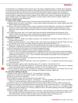
Figure 2 | Predictions of oxygen profiles (micromolar) in a channel and tissue space of a construct with
cell density of 1 108 cell ml1, 100-mm channel diameter and 100-mm wall-to-wall spacing. Perfused at
a velocity of: (a) 490 mm s1 and (b) 1.35 mm s1 with control medium (0% perfluorocarbon (PFC), left
panels) and medium supplemented with 6.4% volume PFC emulsion (right panels); vertical lines designate
channel walls. Adapted with modifications from ref. 32.
NATURE PROTOCOLS | VOL.3 NO.4 | 2008 | 723](https://image.slidesharecdn.com/williambioreactor2014-140913174921-phpapp01/85/William-bioreactor-2014-5-320.jpg)


This document describes a protocol for engineering cardiac tissue using perfusion bioreactor systems. Cardiac cells are seeded onto porous scaffolds and cultured in bioreactors with perfusion of culture medium, which provides oxygen to the cells and overcomes limitations of conventional static culture. Two approaches are discussed: interstitial flow through porous scaffolds and flow through channel arrays in scaffolds. Perfusion improves cell viability, density, and function compared to static culture and enables engineering of thicker cardiac constructs.


![Human Reproduction [ Reproductive System ] Notes @irfanullah_mehar Irfanullah...](https://cdn.slidesharecdn.com/ss_thumbnails/humanreproductionreproductivesystemnotesirfanullahmeharirfanullahmeharjanantantra-260111172350-56e85778-thumbnail.jpg?width=640&height=640&fit=bounds)


