LTE Fundamentals Training and Certification by TELCOMA Global
The document outlines an extensive overview of LTE (Long Term Evolution) technology, including its history, network architecture, and key features such as high data rates and reduced latency compared to previous technologies. It describes the components of the LTE network including the Evolved Packet Core (EPC) and the Radio Access Network (RAN), as well as various interfaces and physical channels involved. Additionally, the document highlights advancements in LTE-Advanced and the concept of Carrier Aggregation for increased bandwidth efficiency.
Overview of LTE and key components such as network architecture, RAN, EPC, and UEs.
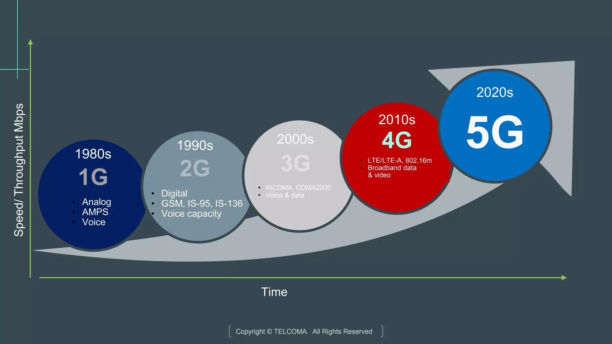
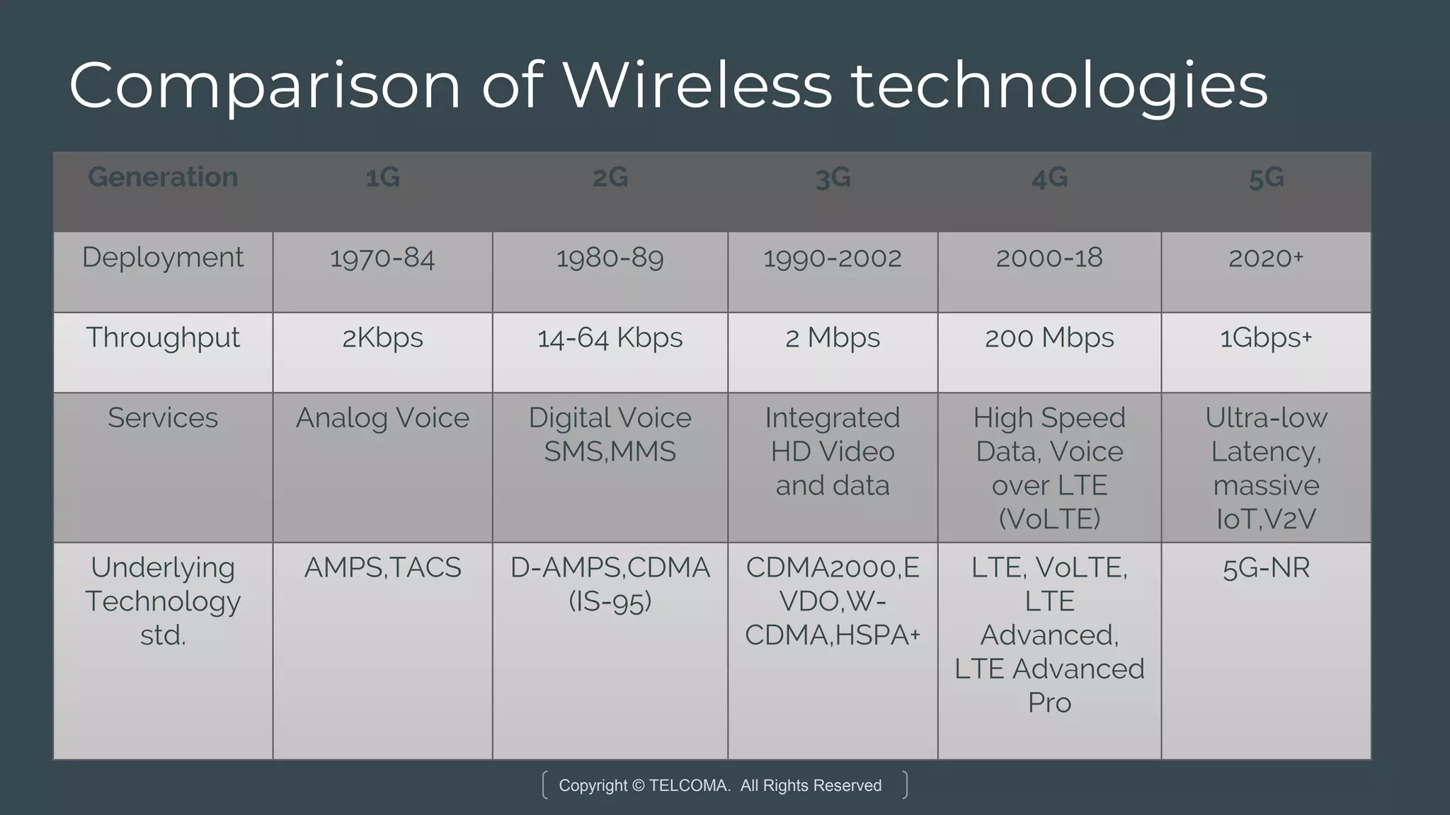
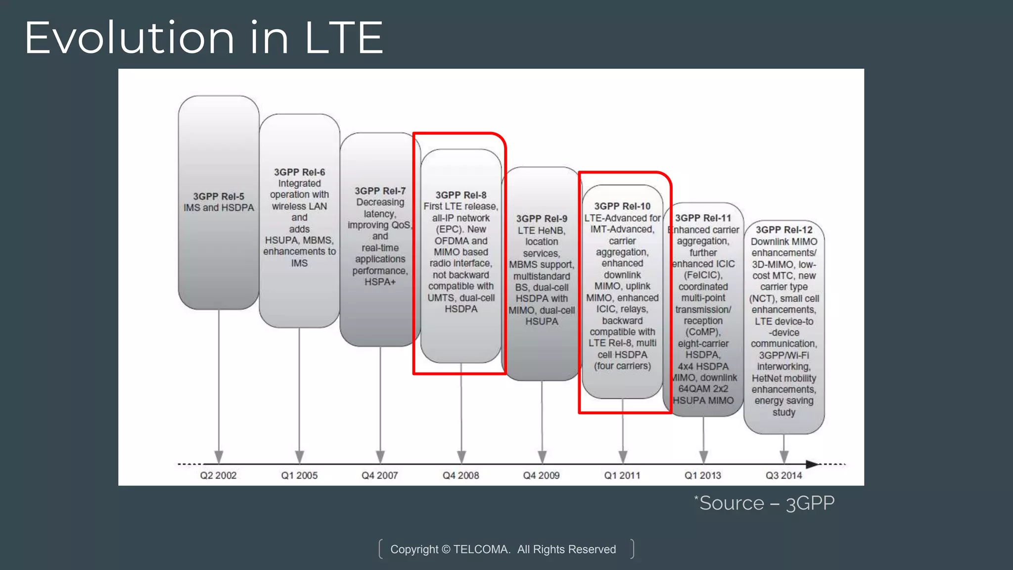
A timeline of wireless technology from 1G to 5G highlighting advancements in data speed and capacity.
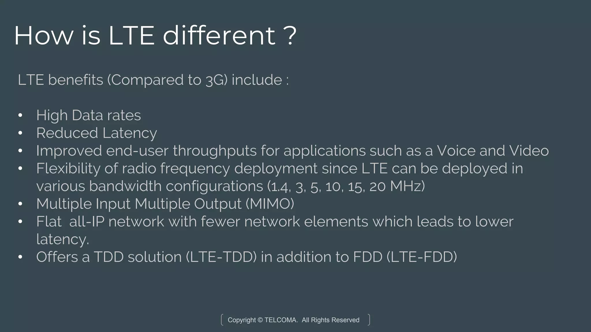
Key differences of LTE include higher data rates, reduced latency, and efficient bandwidth utilization.
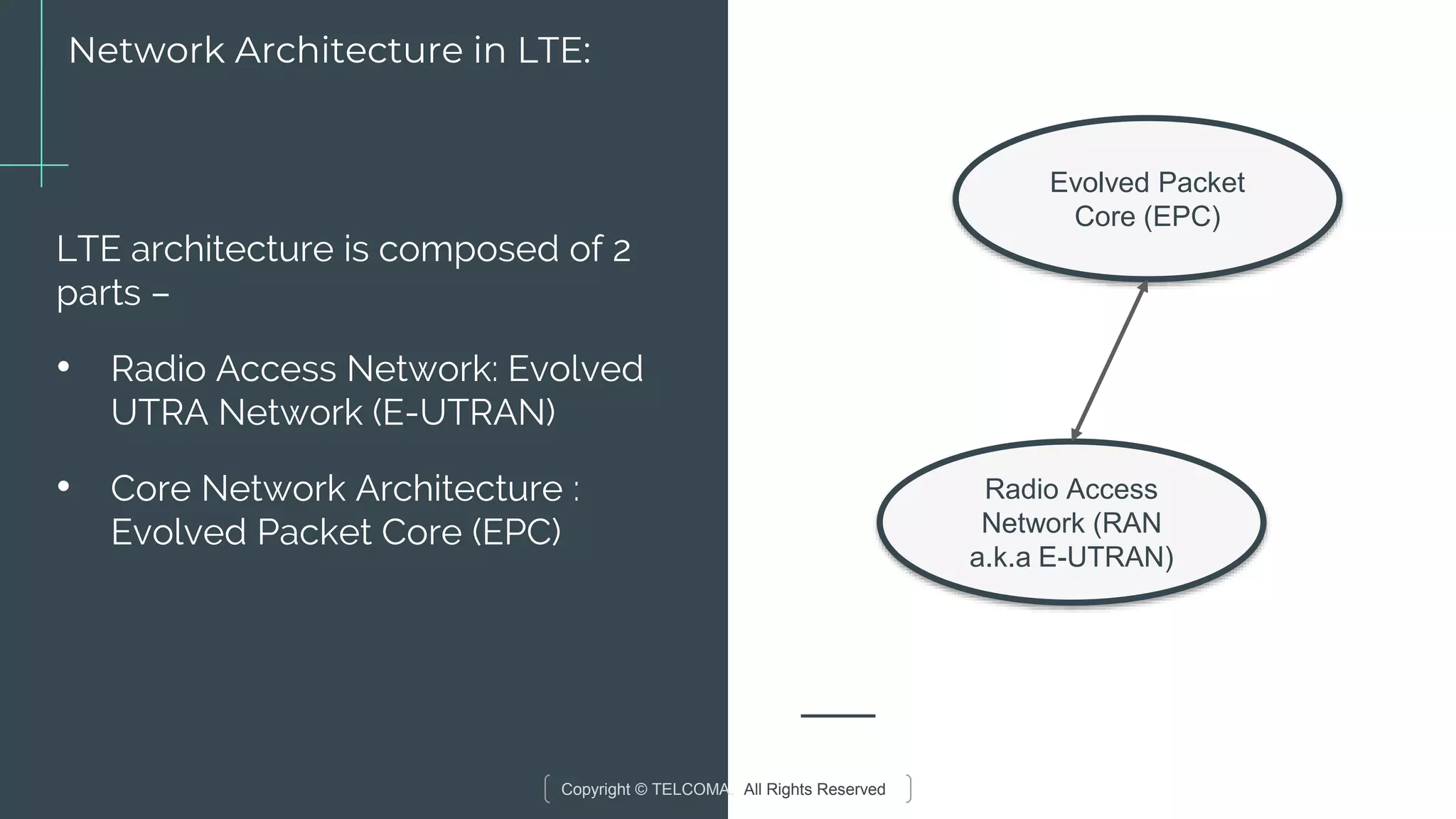
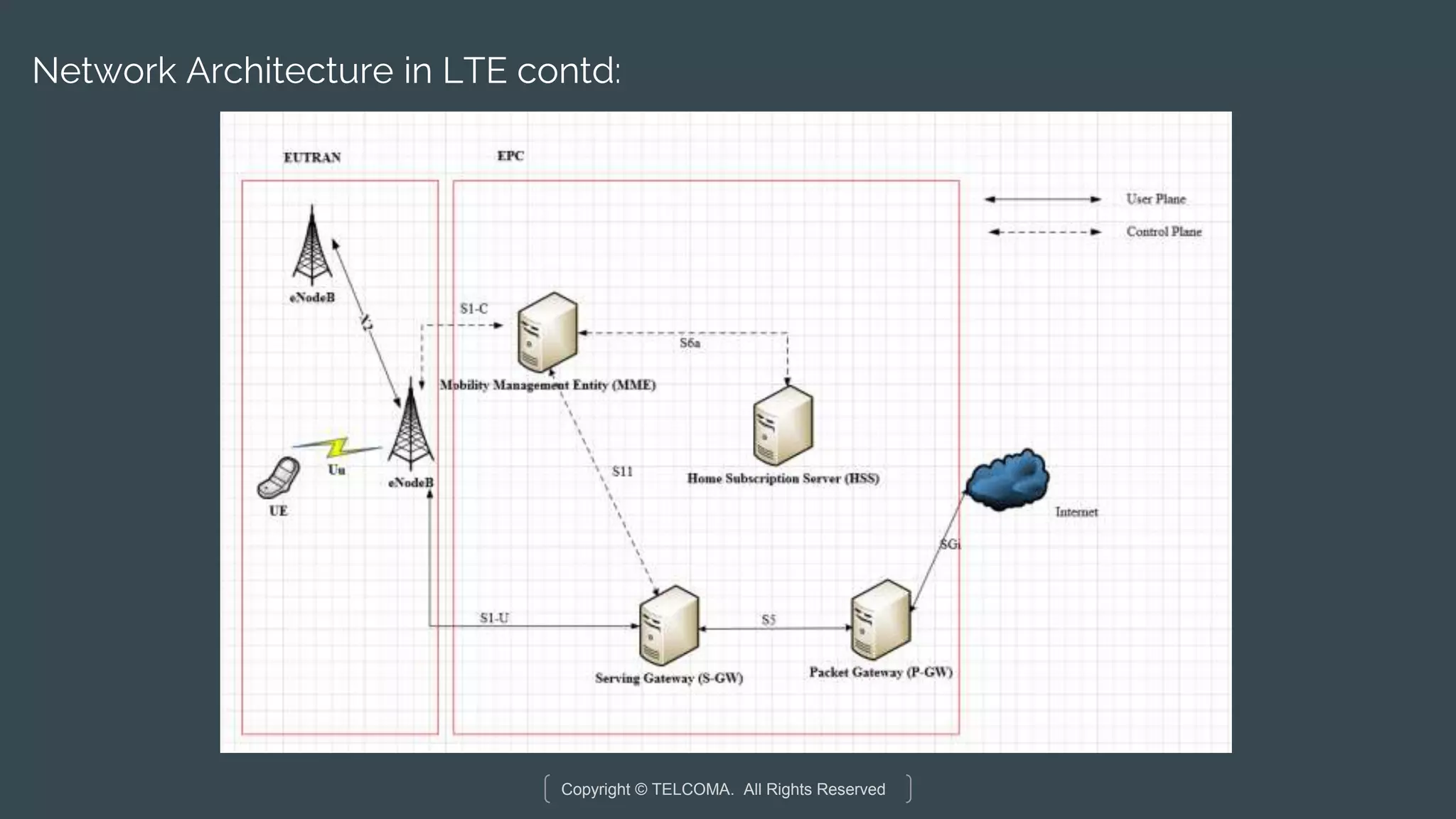
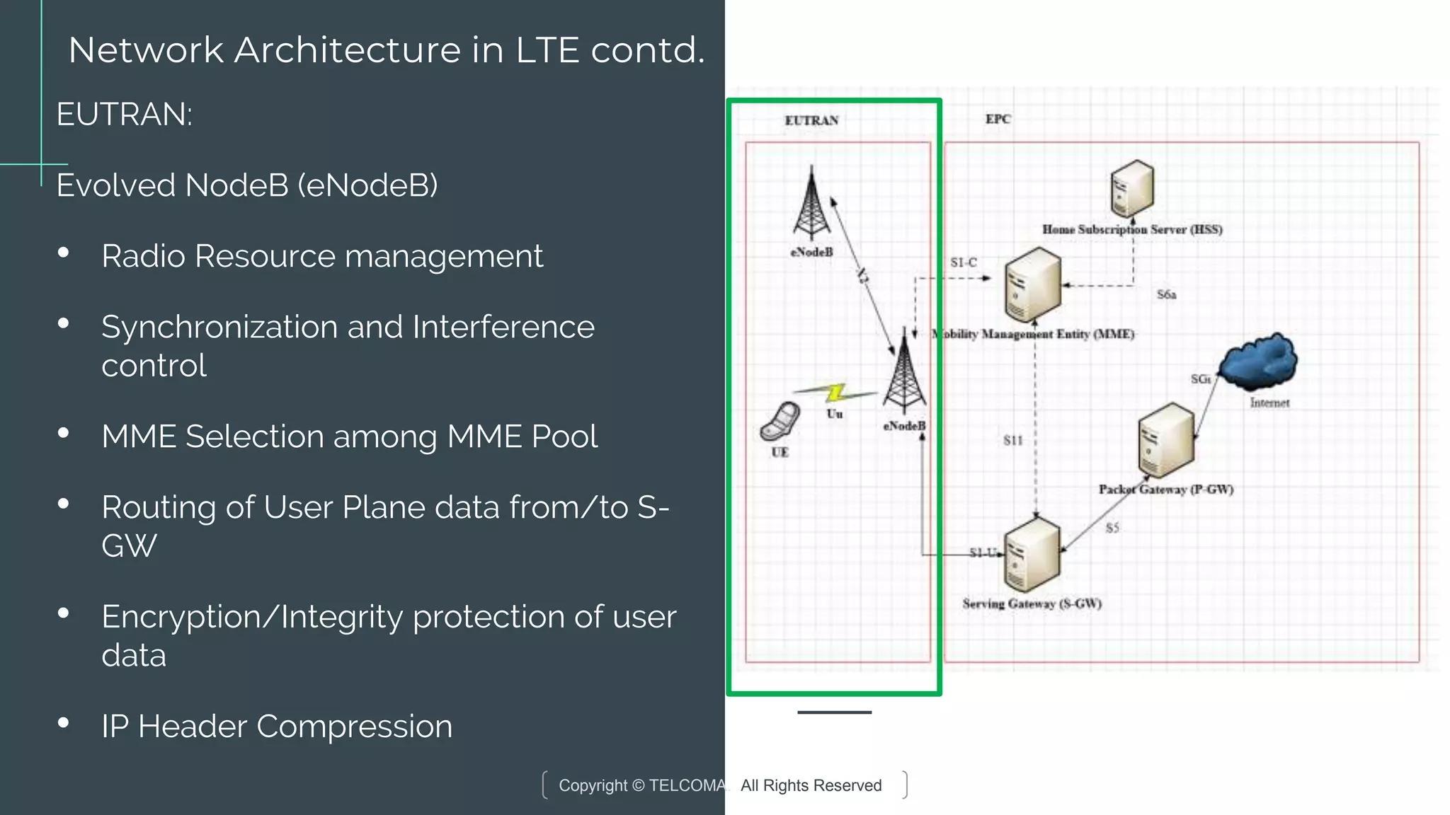
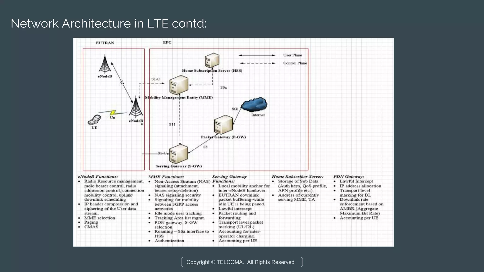
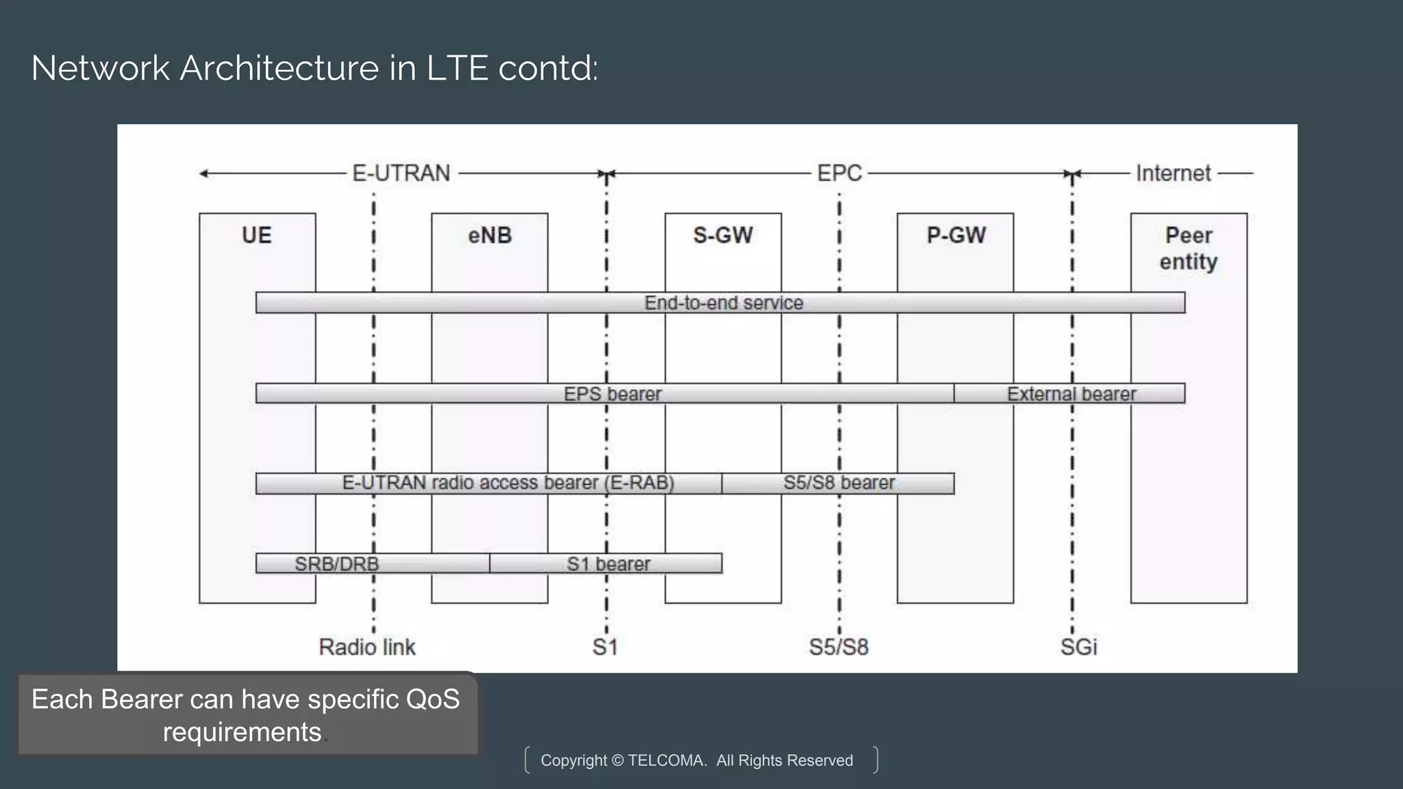
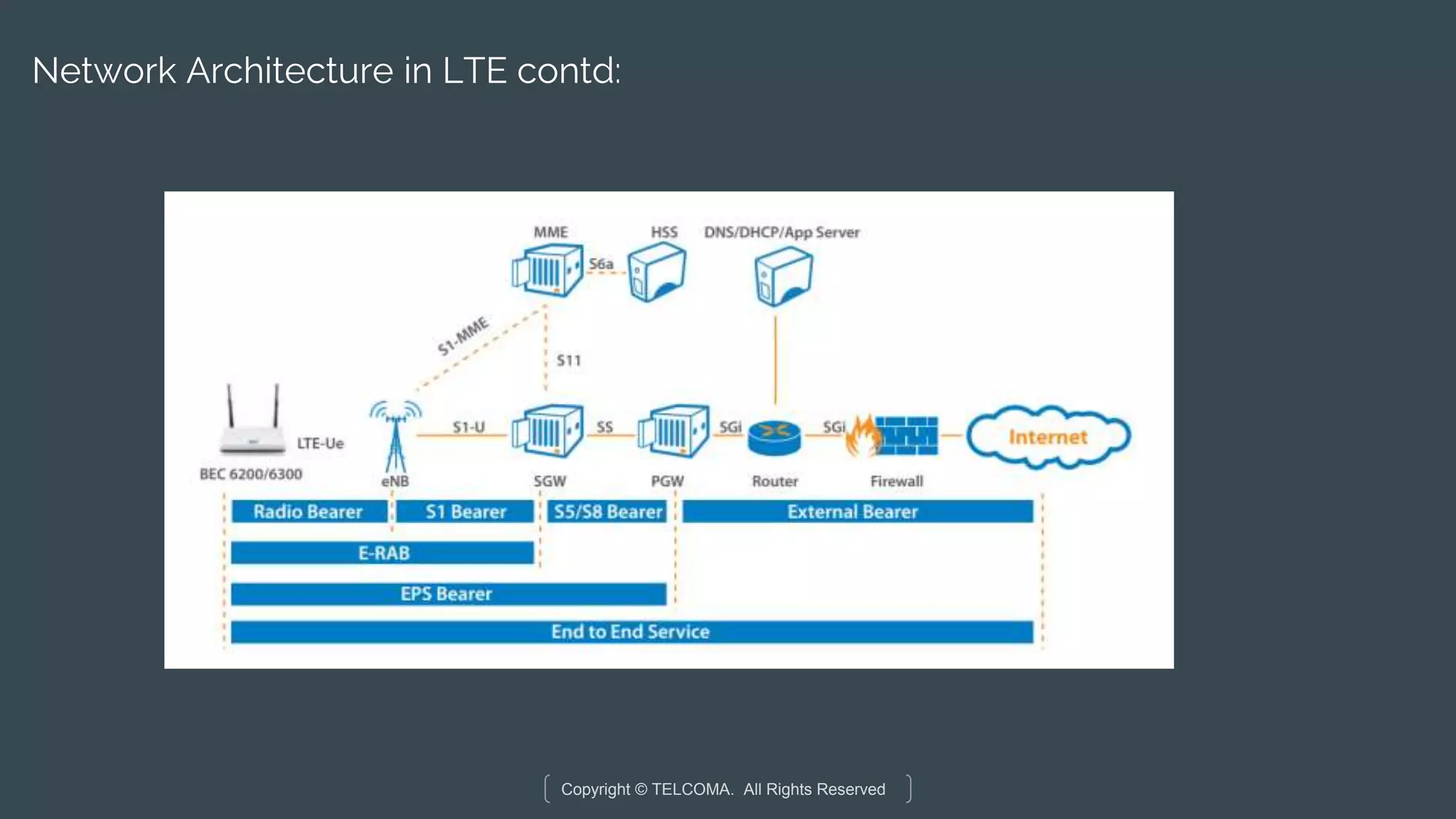
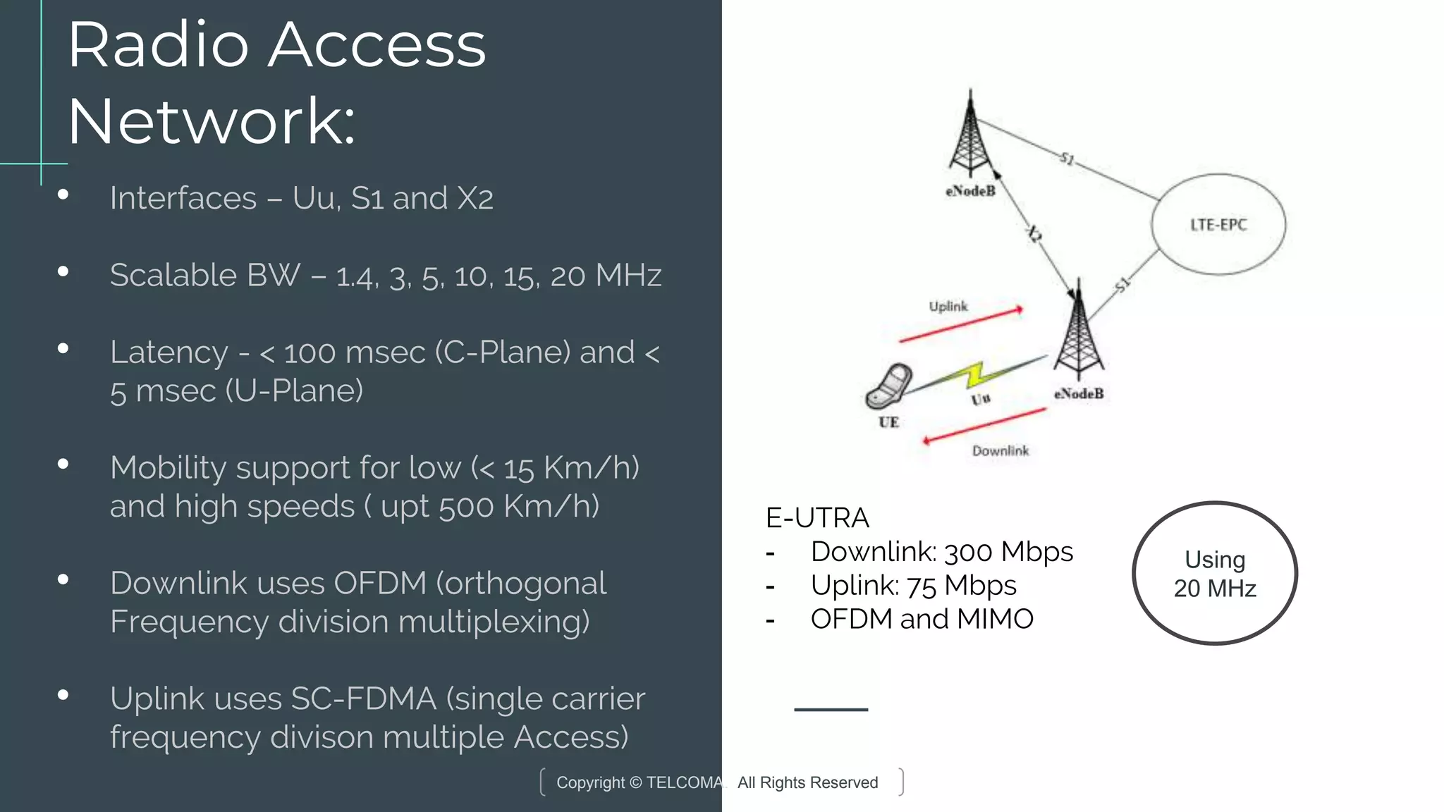
Detailed architectural components of LTE system including RAN and EPC, and their functions.
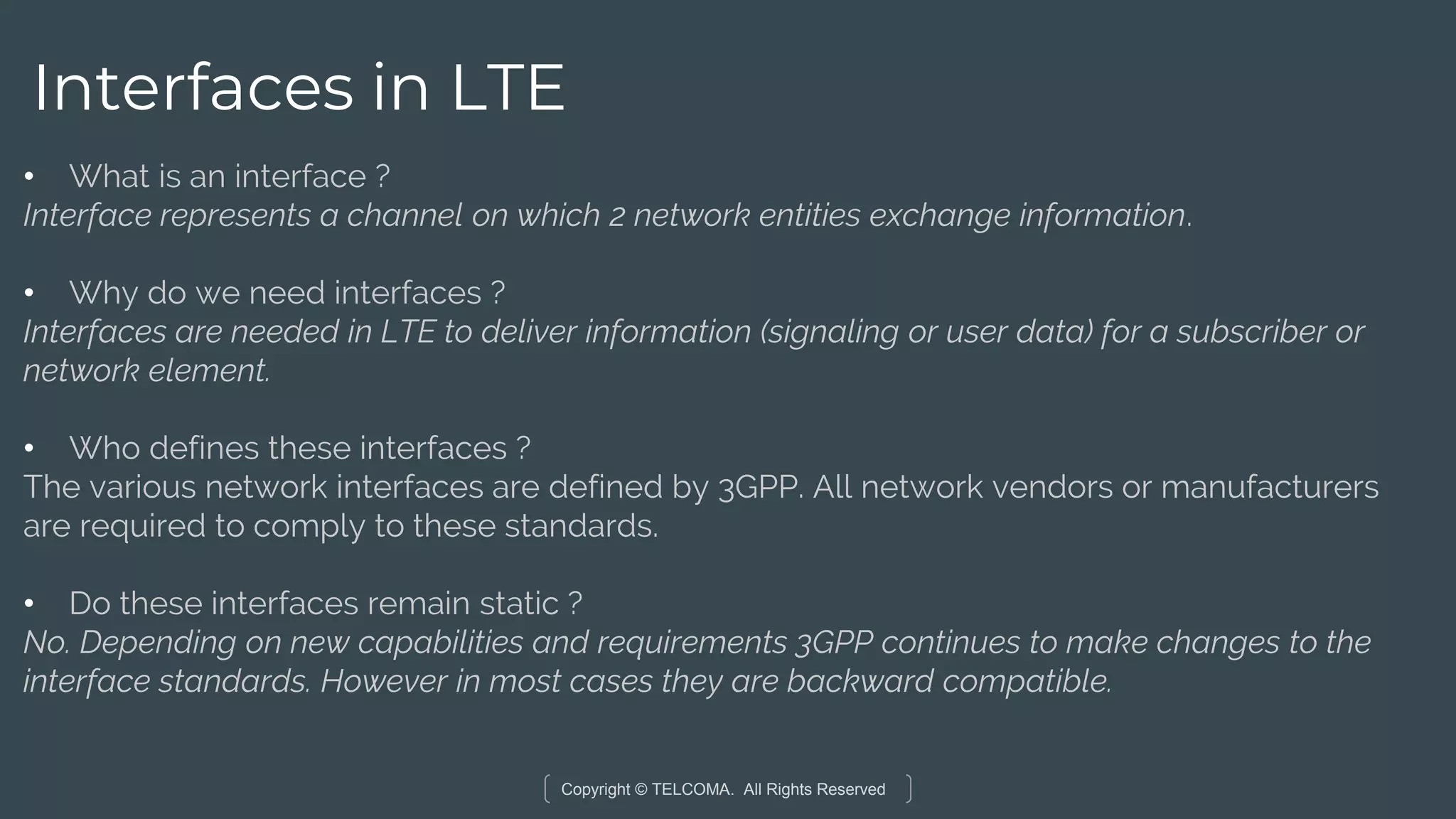
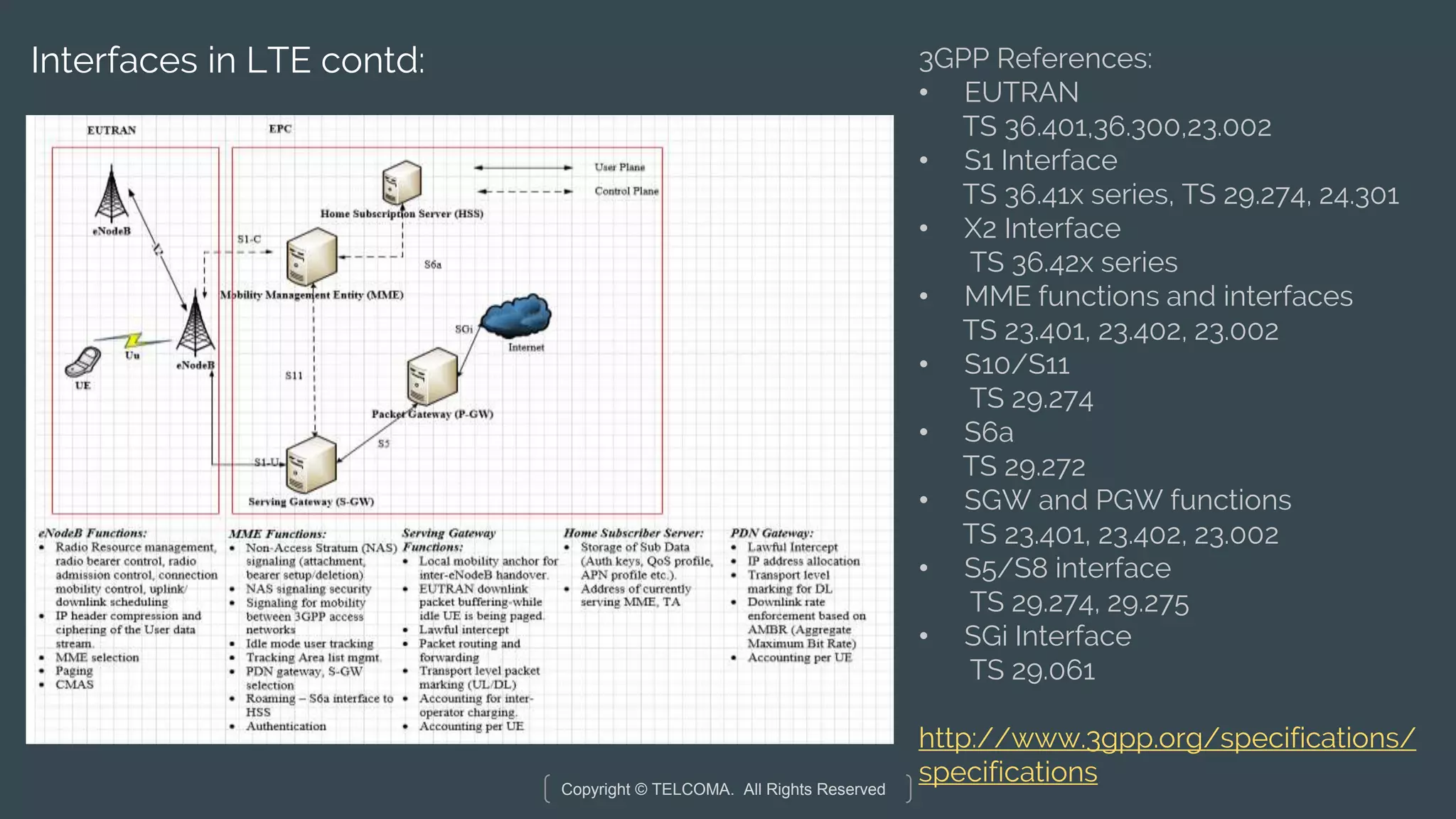
Definition and importance of interfaces in LTE for communication between network entities.
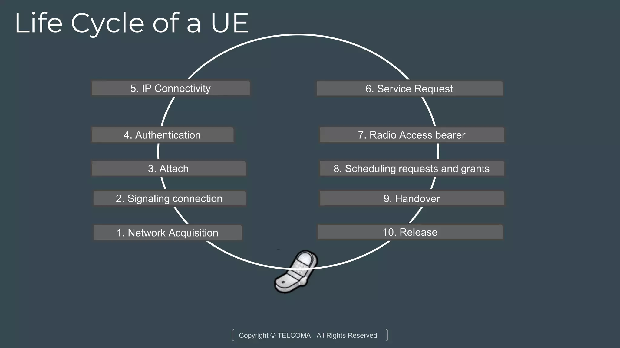
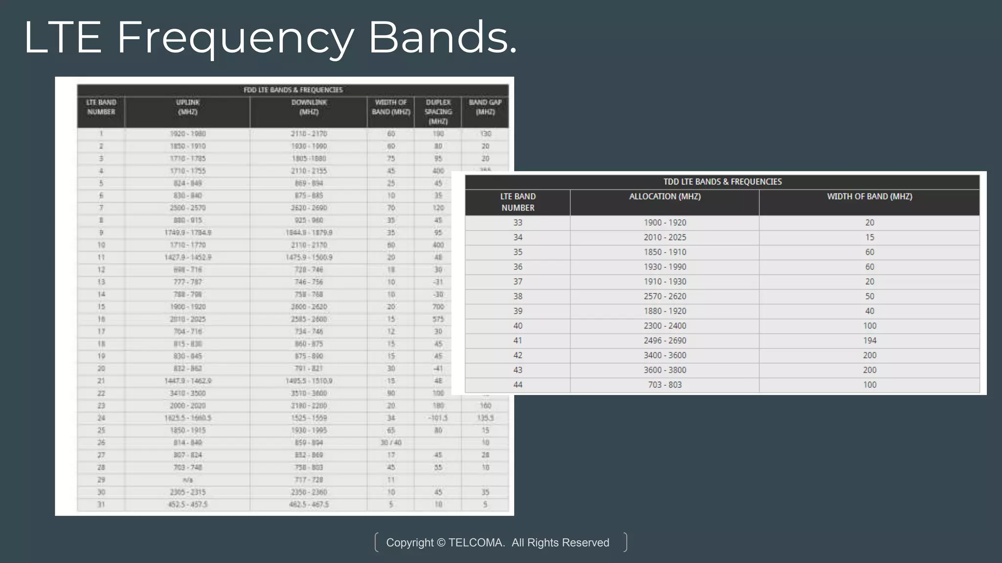
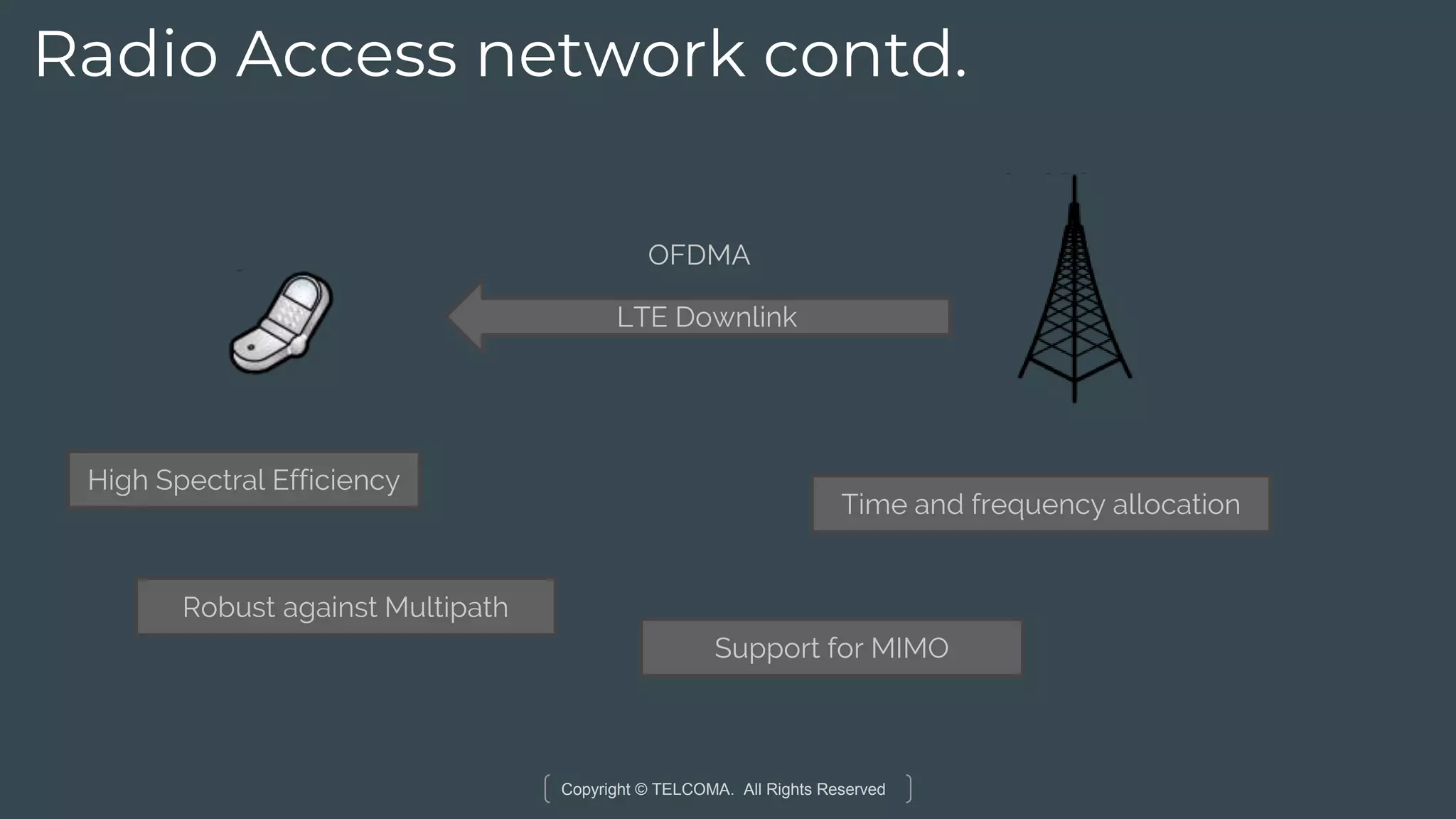
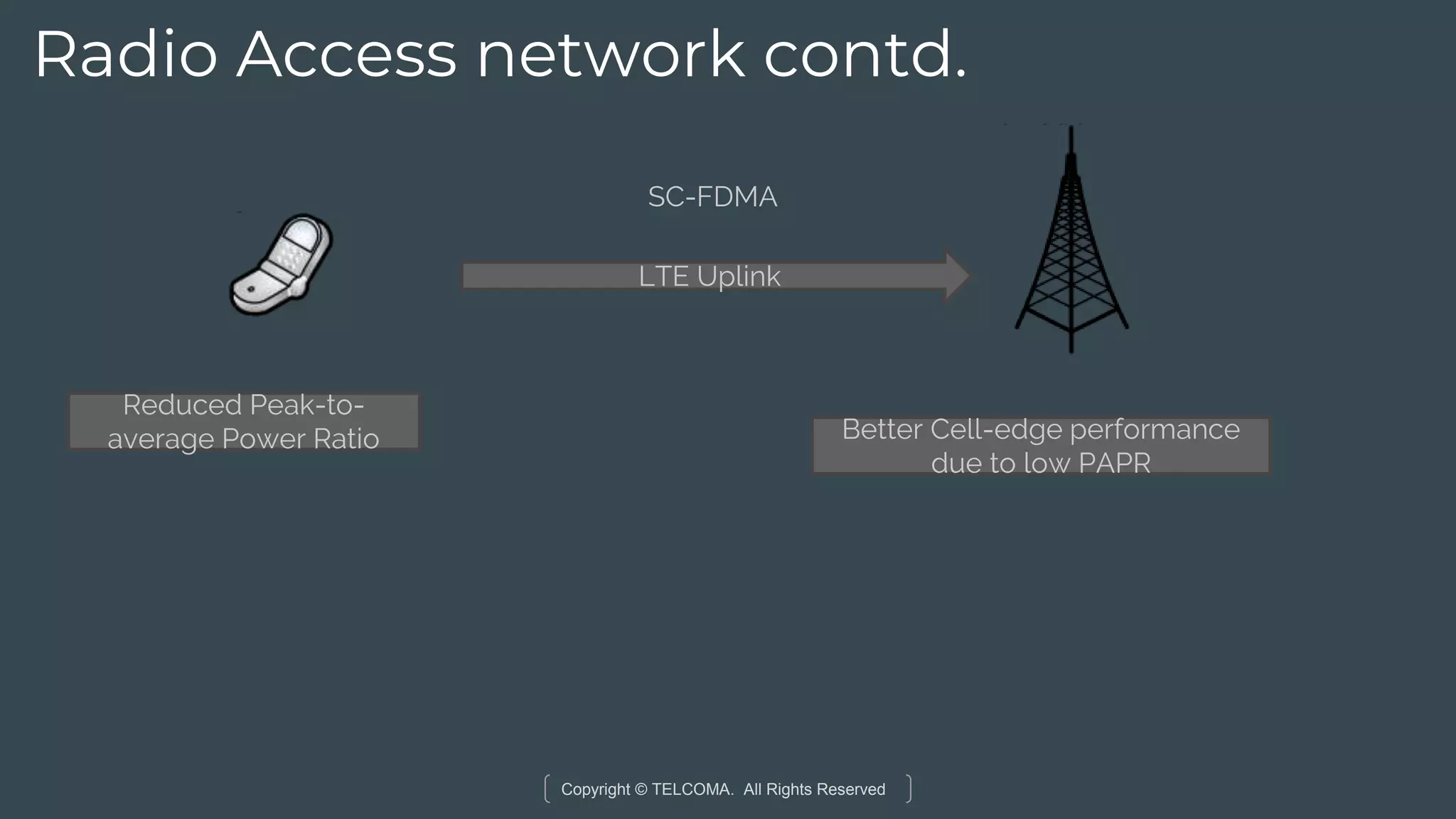
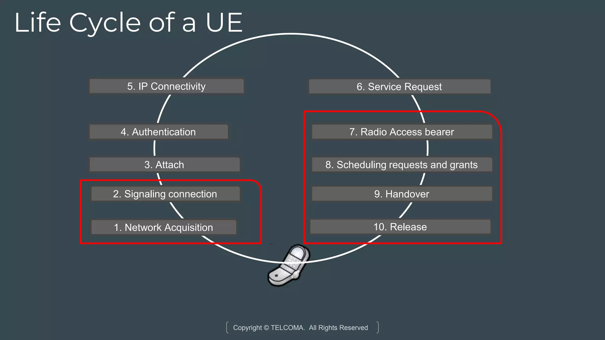
The stages of a UE's connection from initial network access to service request and handover.Technical details on RAN including bandwidths, latency, and multiplexing techniques in LTE.
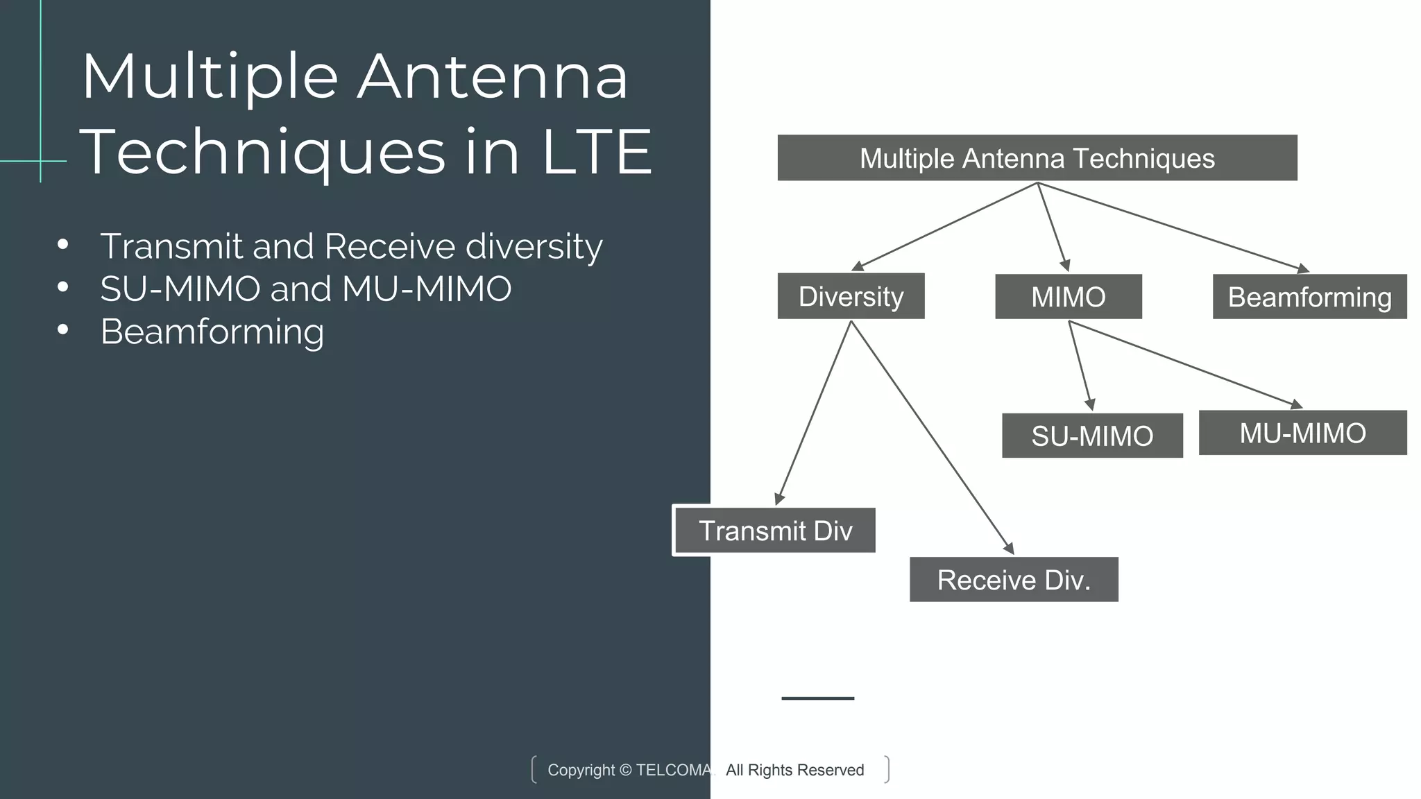
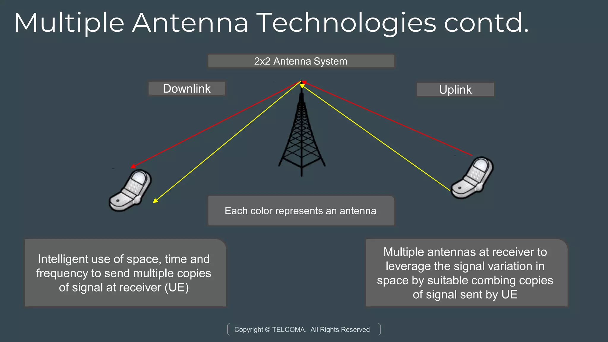
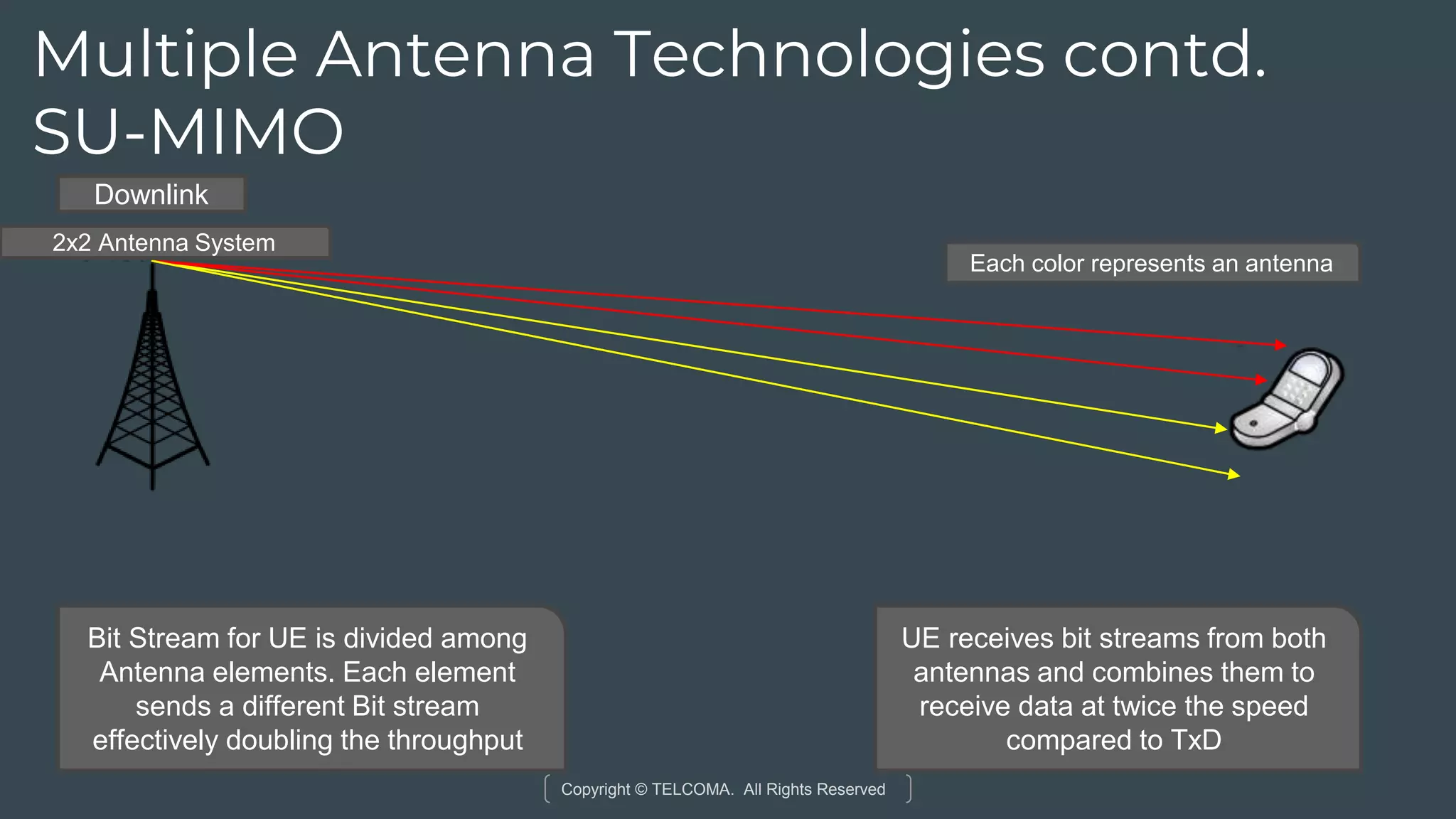
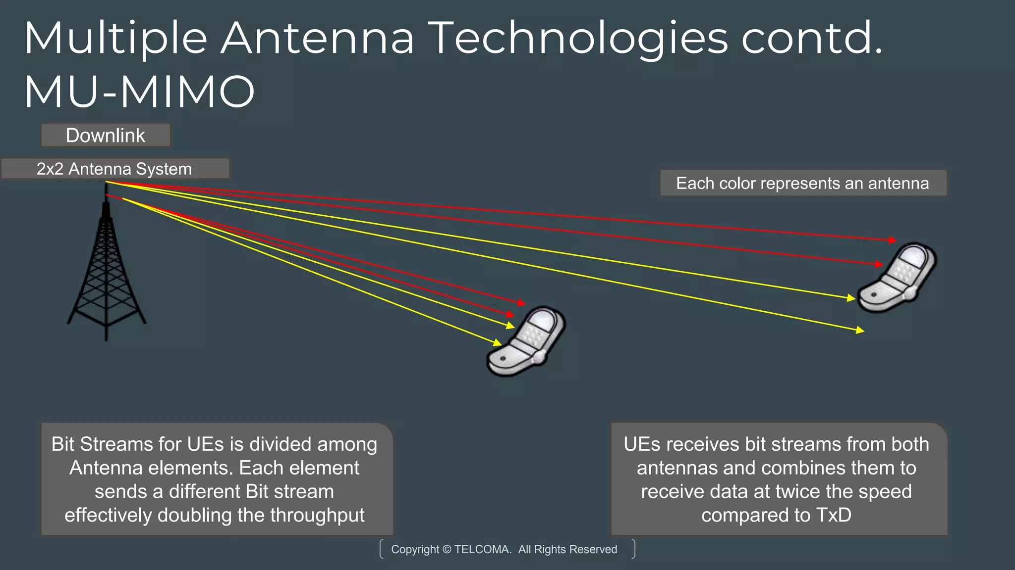
Overview of MIMO techniques for enhancing data throughput in LTE, including SU-MIMO and MU-MIMO.
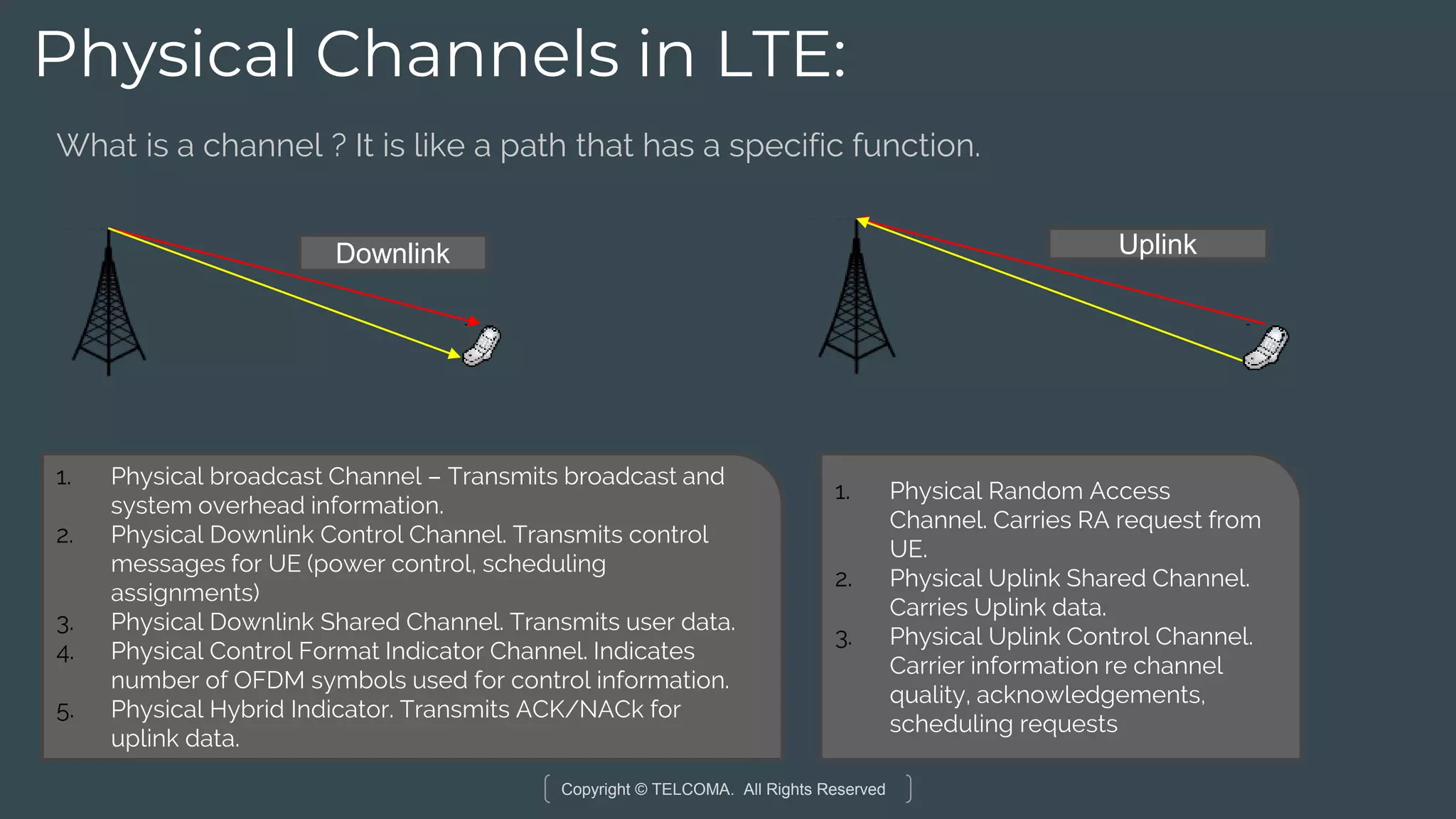
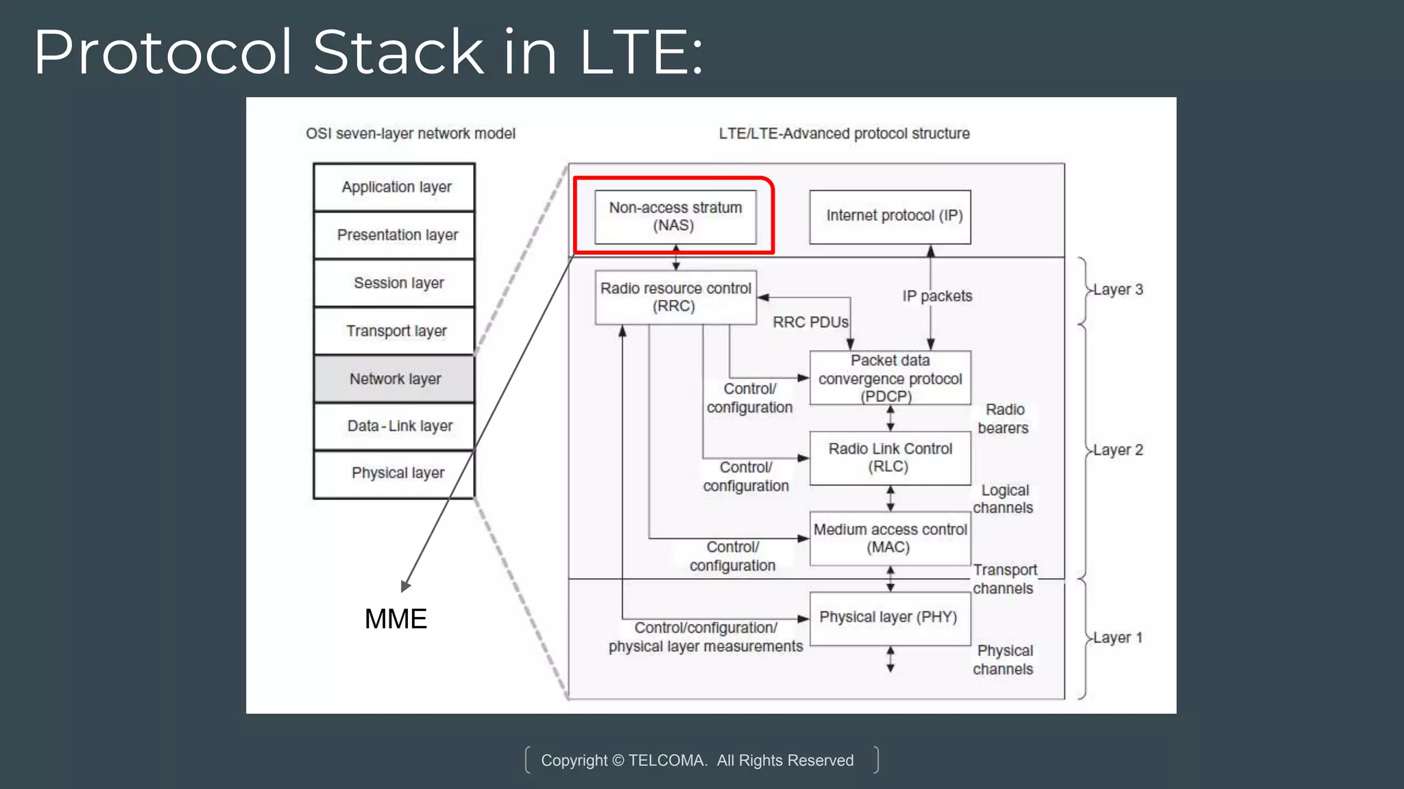
Various channels in LTE for data and control transmission, and an overview of the LTE protocol stack.
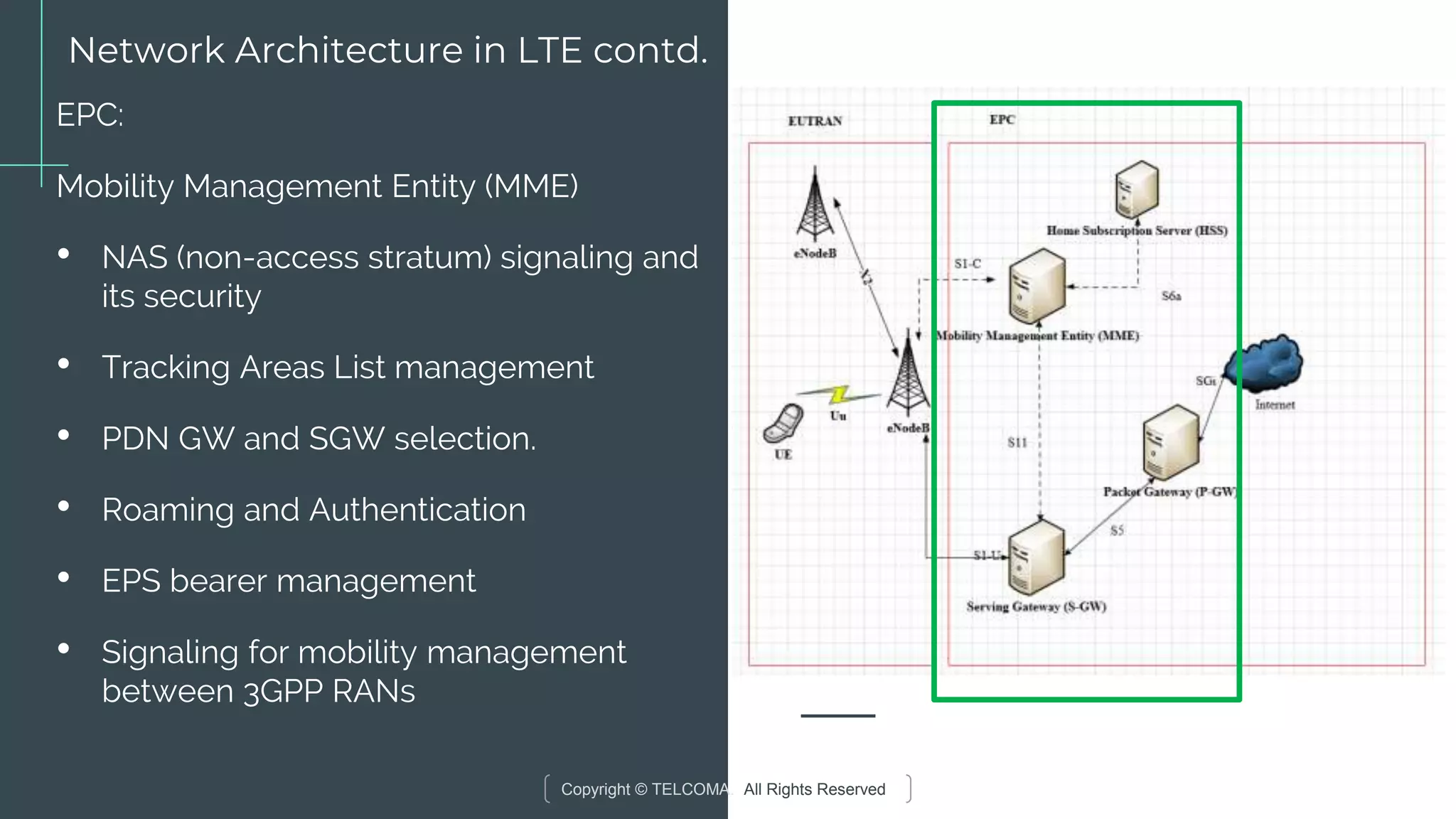
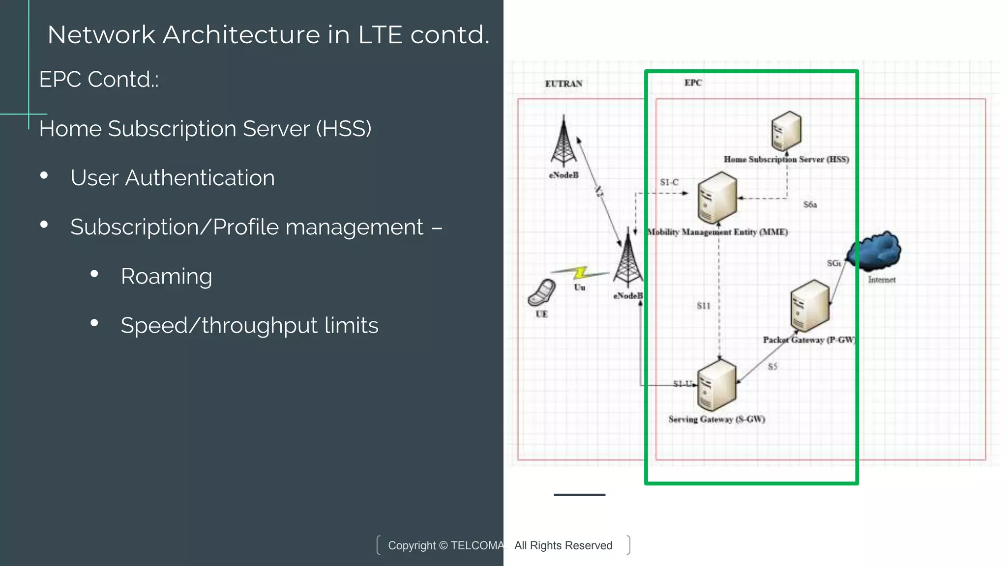
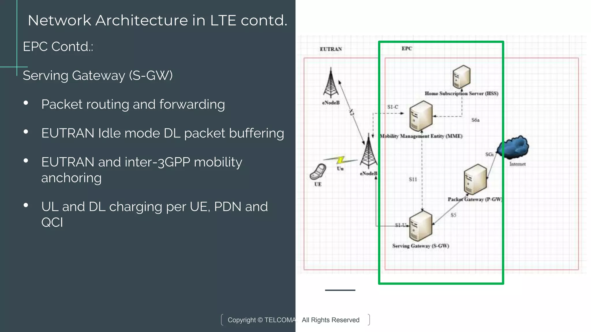
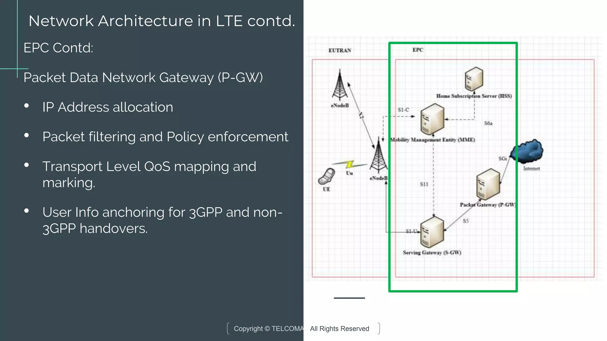
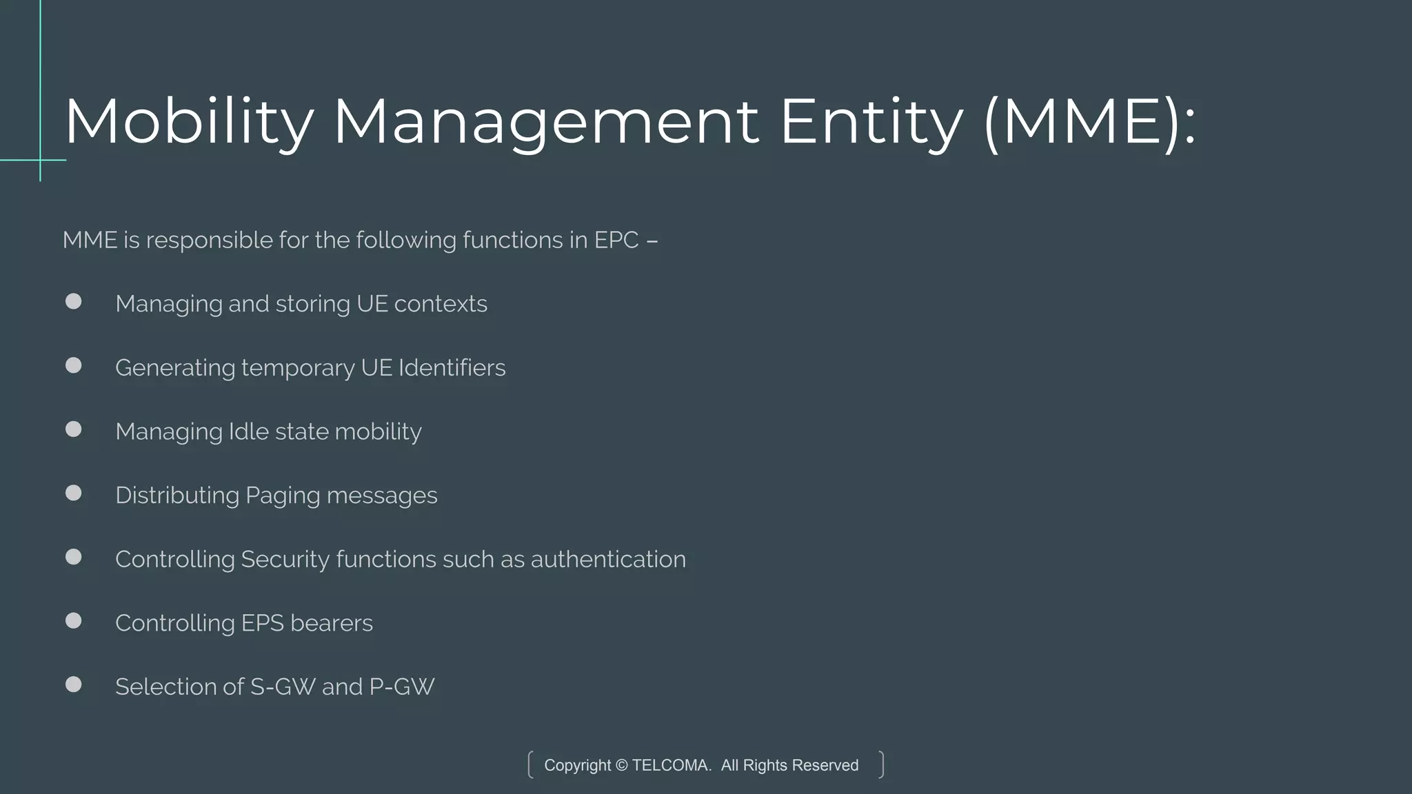
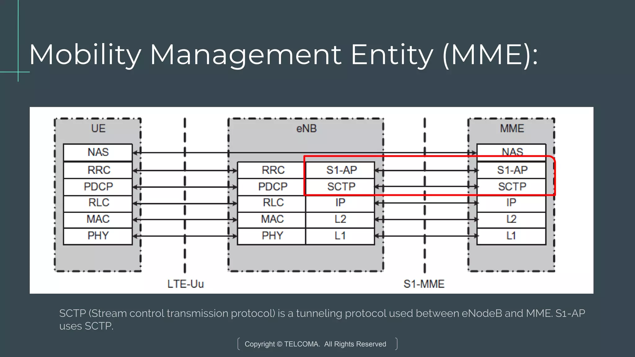
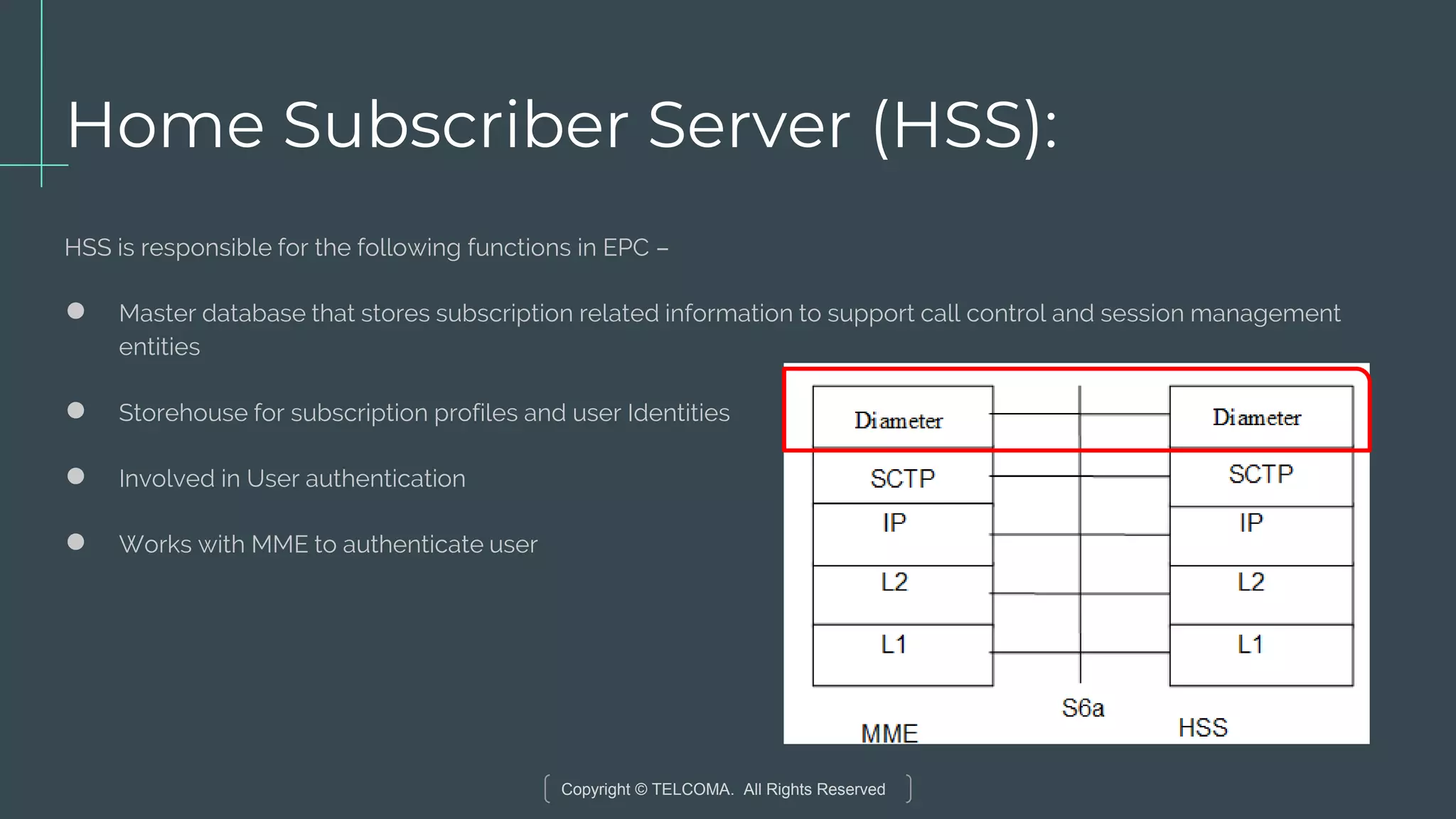
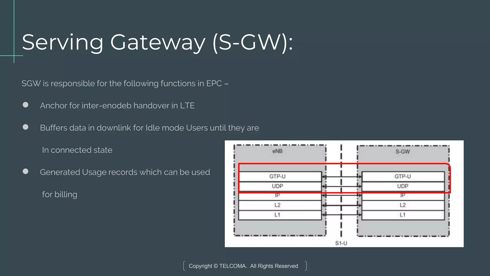
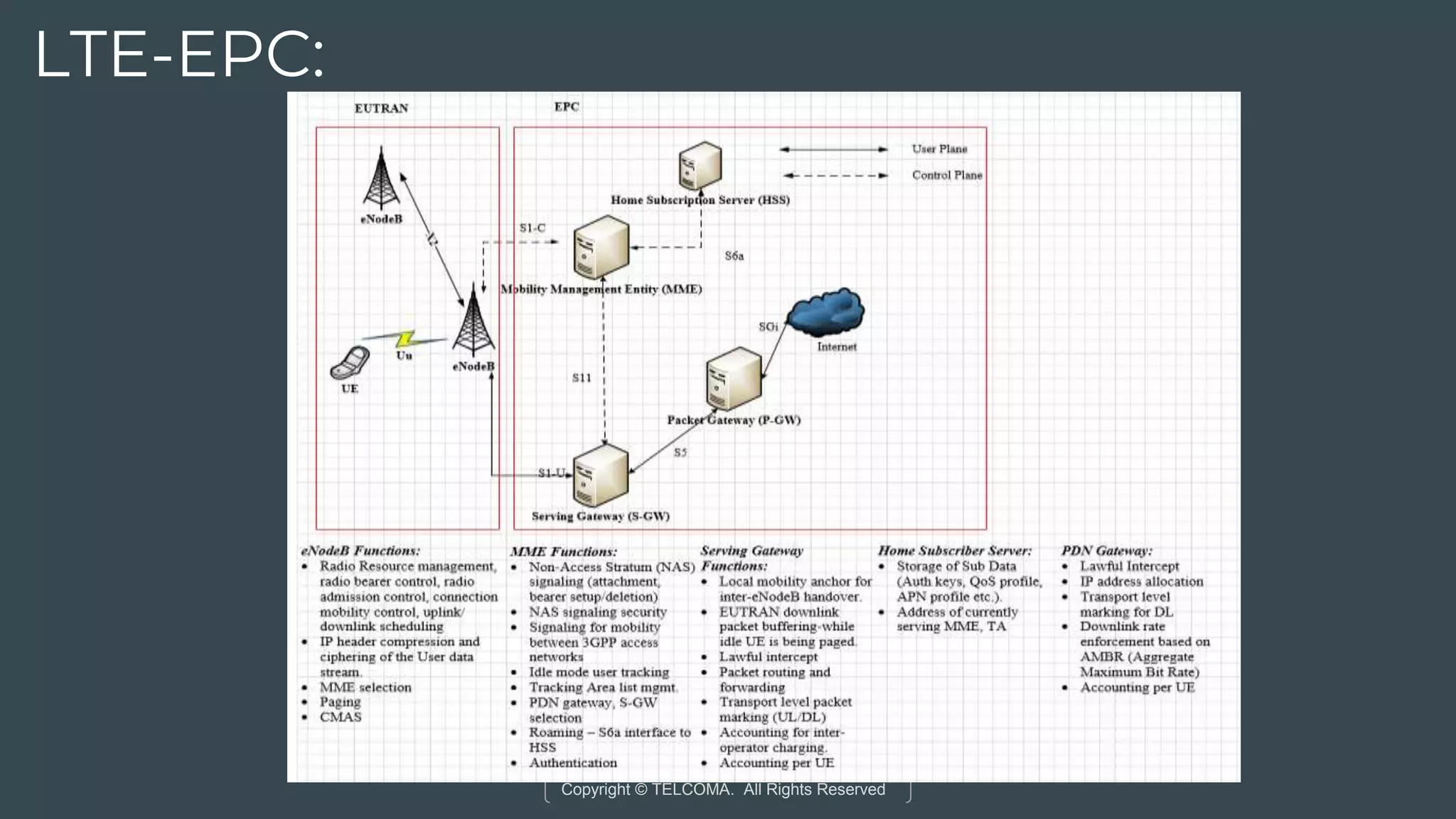
Key components of EPC like MME, HSS, S-GW, and P-GW, highlighting their roles in managing UE and data.
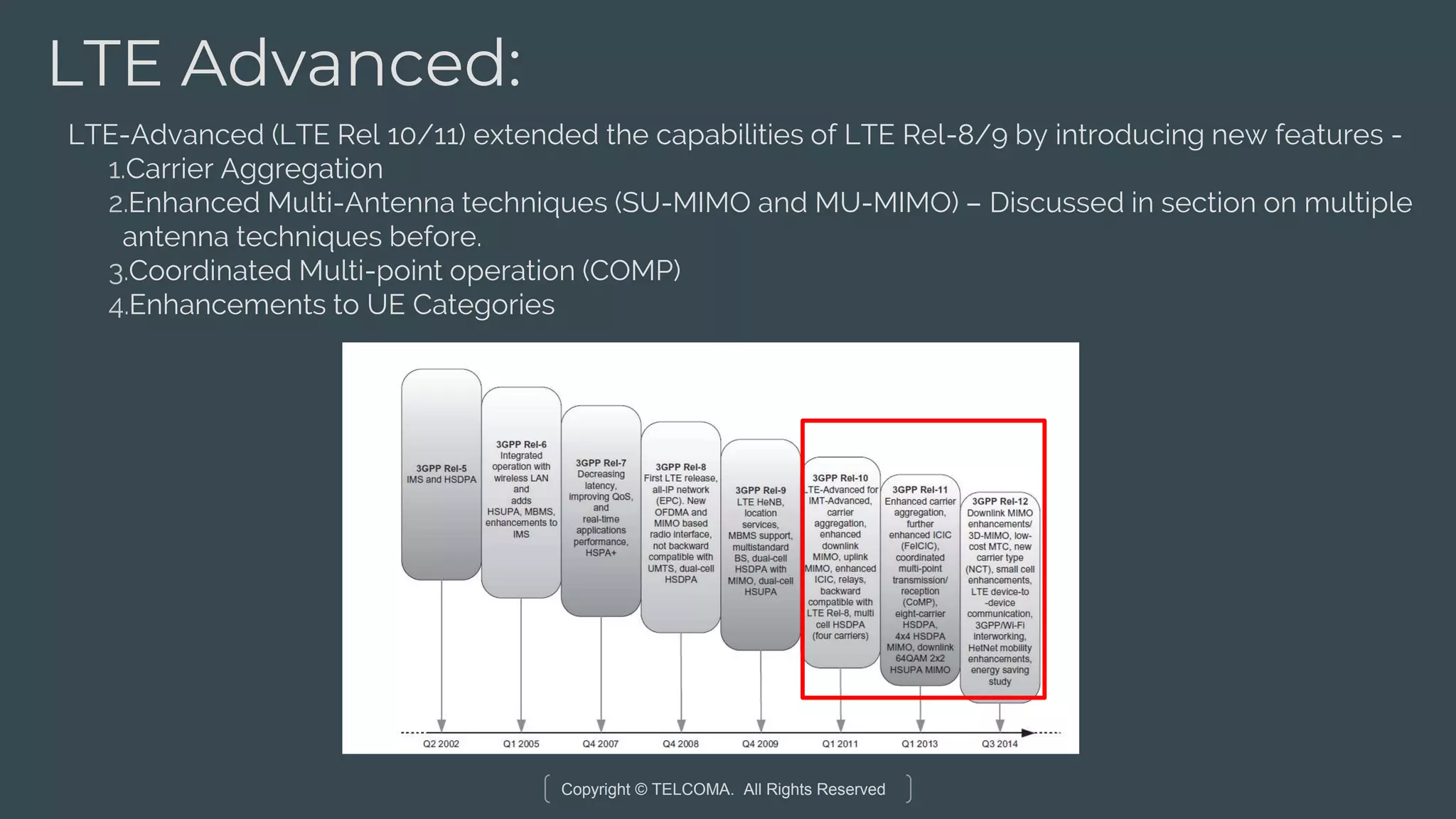
Introduction of carrier aggregation for enhancing throughput and supporting wider bandwidth scenarios.
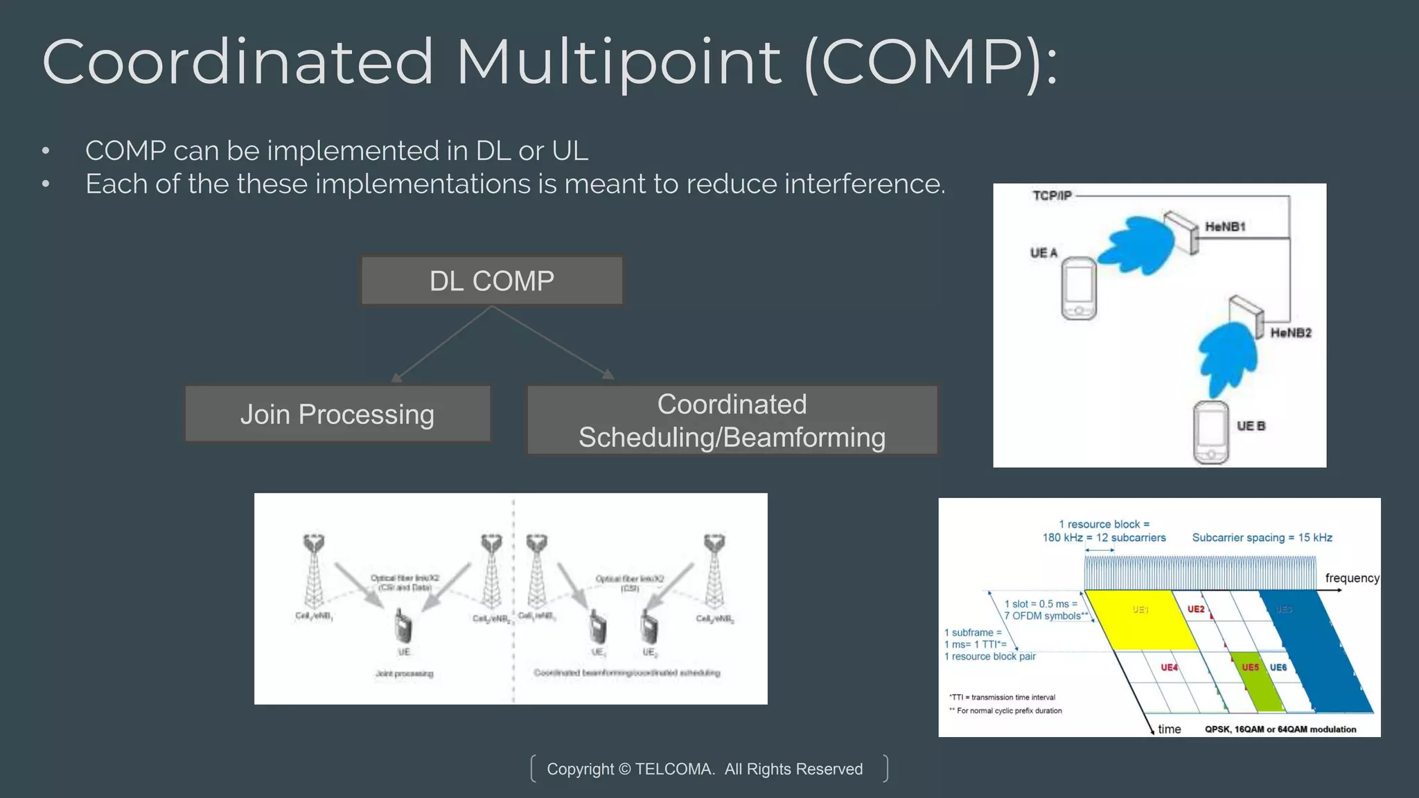
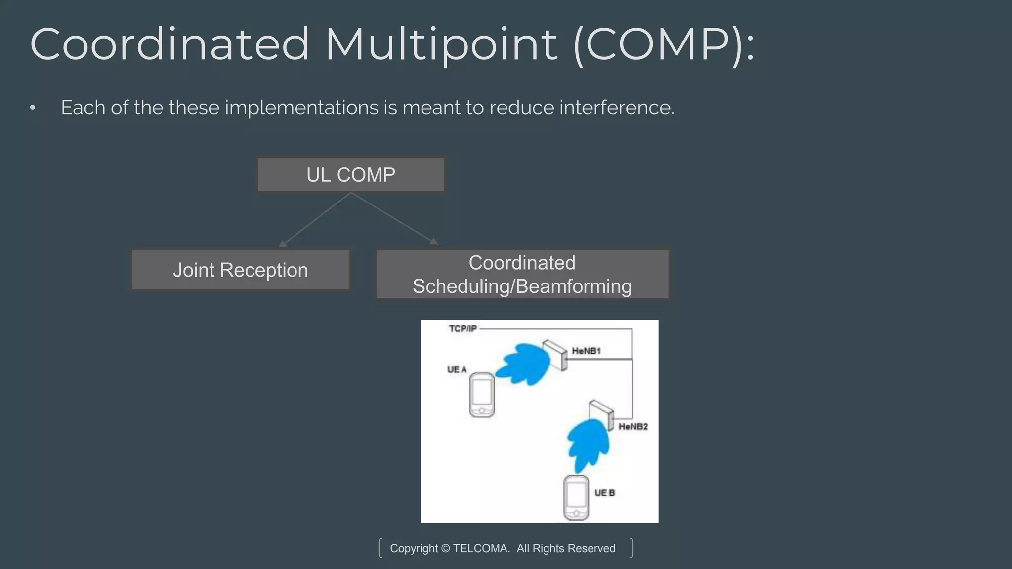
Strategies in DL and UL COMP to mitigate interference and enhance the quality of service.
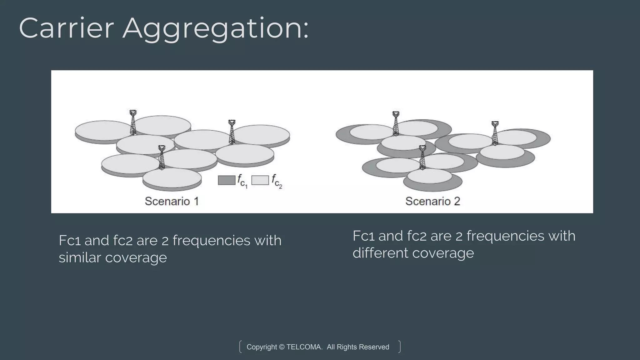
#9 - Caters to variety of Operators – Spectrum rich and not so Spectrum rich
#11 UTRA stands for Universal Terrestrial Radio Access
Has 2 parts
#12 Eutran is also known as RAN
UE is User equipment
Is the closest to the UE
EPC is centrally located or can be distributed according to Geography
User Plane and control Plane.
Difference explain
#13 Next we will break it out
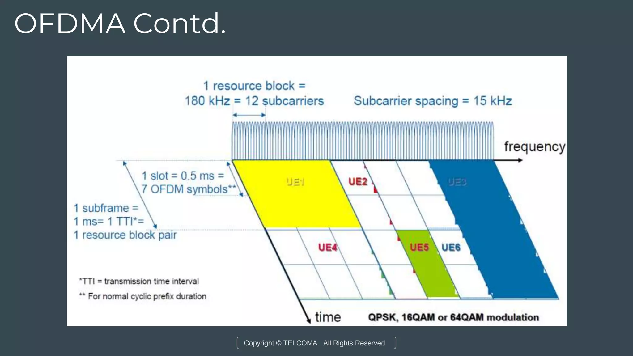
What is radio resource ? Chunks of Spectrum
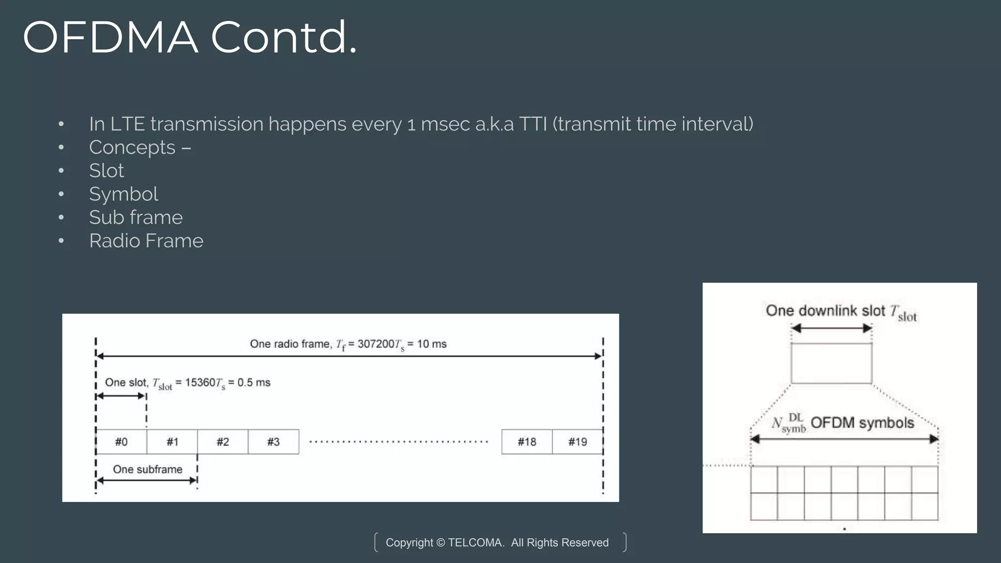
Synchronization – Multiple users are transmitted at the same time. Need to keep them in sync. Resources are finite.High Speed data so timing is critical
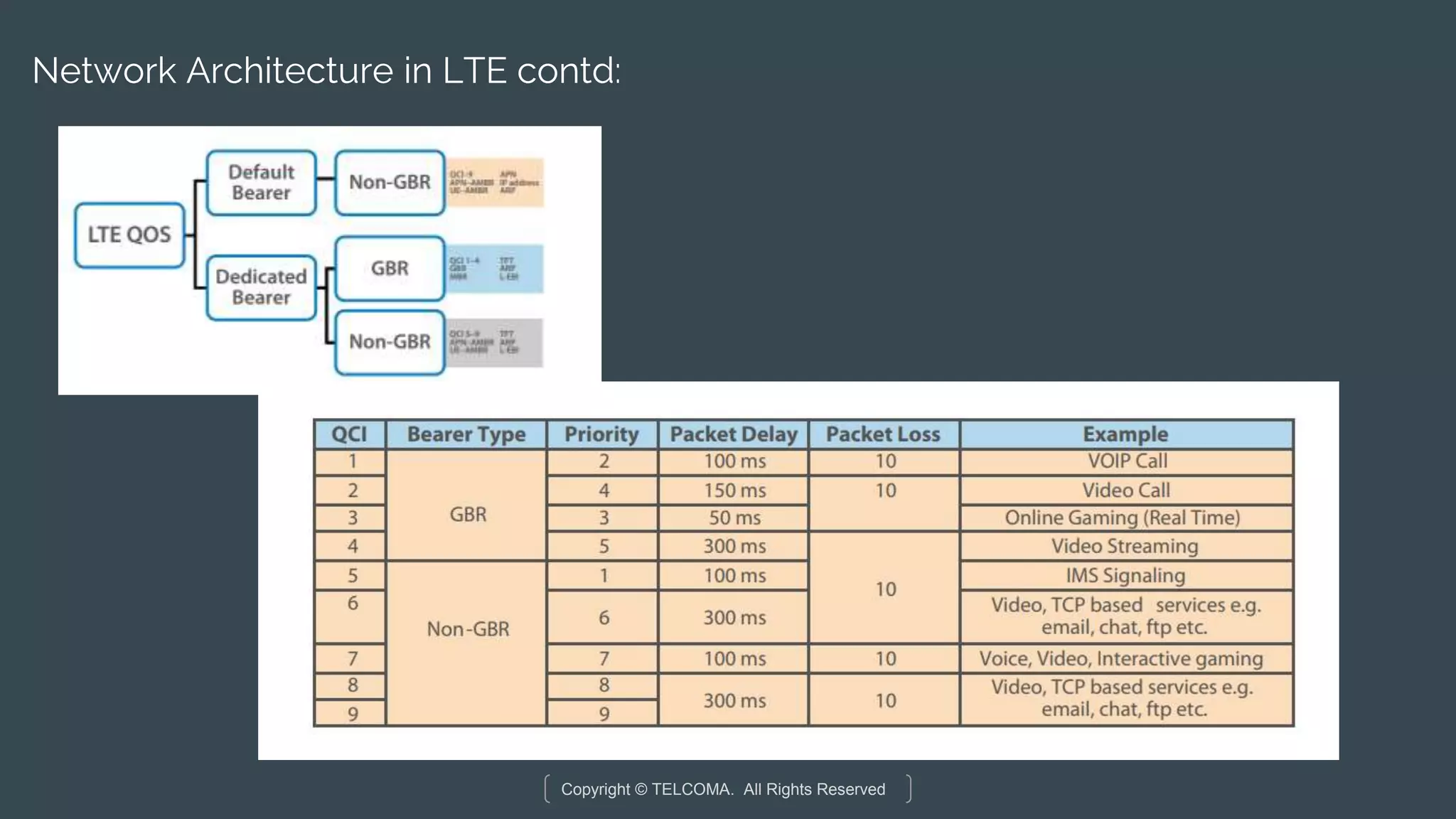
#19 What is a bearer ? Logical connection between entities. Can be composed of multiple Bearers
#21 Imagine you have LTE router/Mifi device. This picture shows the end-to-end connection
#28 Imagine you are riding a Taxi and you pick up your phone to send a whatsapp Text. Trace the steps of the process. In the subsequent sections we will take a look at each aspect
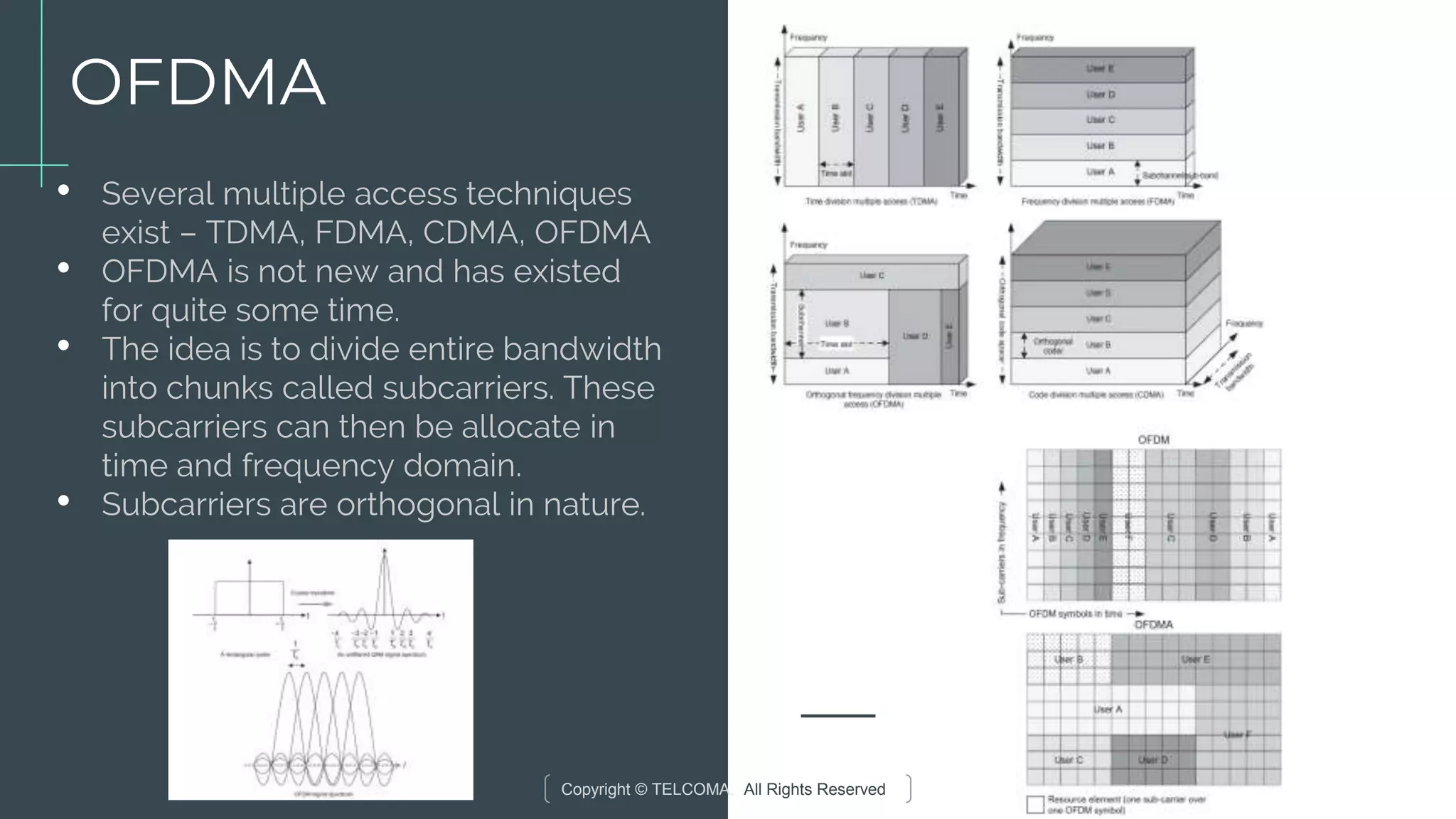
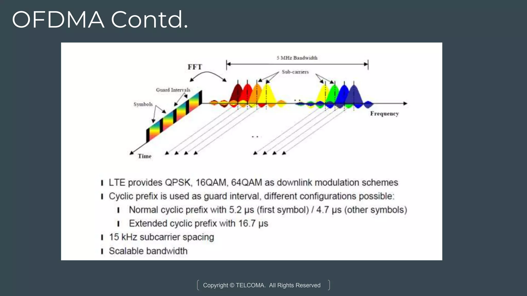
#31 OFDM converts a single carrier system to n-carrier one. The advantage is that data rate of each subcarrier is 1/n of total data rate, which expands symbol time by a factor of n. We love large symbol time as it makes the system robust against intersymbol interference (ISI)
#32 OFDM converts a single carrier system to n-carrier one. The advantage is that data rate of each subcarrier is 1/n of total data rate, which expands symbol time by a factor of n. We love large symbol time as it makes the system robust against intersymbol interference (ISI)
#33 A major challenge associated with OFDM is high PAPR of the transmitted signal. This is a consequence of the IFFT summing of multiple independent symbols, which are all integer number of cycle over the symbol time; whenever they add constructively the result is a high peak power.
SC-FDMA also has High PAPR but it is overcome by transmitted symbols sequentially rather in parallel.
#43 Channel – think of it as a transport mechanism that leads to a specific destination and has a specific purpose. Airports for planes, railway station for trains
#46 Tasks in Red boxes are mainly controlled by EUTRAN. Rest are controlled BY EPC
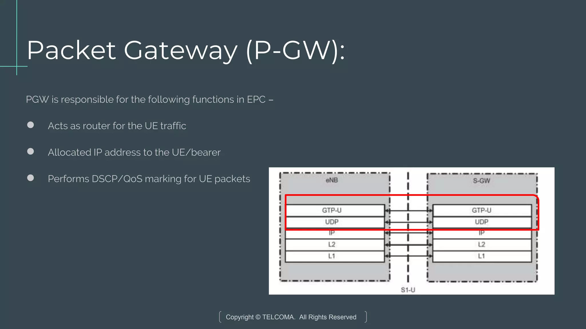
#51 The S1 user-plane interface (S1-U) is a standard reference point between the eNB
and the S-GW. The S1-U interface provides non-guaranteed delivery of userplane
PDUs between the eNB and the S-GW. The user-plane protocol stack on
the S1 interface is shown in Fig. The transport network layer is built on IP
transport and GTP-U is used on top of UDP/IP to carry the user-plane PDUs
between the eNB and the S-GW.
#52 The S1 user-plane interface (S1-U) is a standard reference point between the eNB
and the S-GW. The S1-U interface provides non-guaranteed delivery of userplane
PDUs between the eNB and the S-GW. The user-plane protocol stack on
the S1 interface is shown in Fig. The transport network layer is built on IP
transport and GTP-U is used on top of UDP/IP to carry the user-plane PDUs
between the eNB and the S-GW.
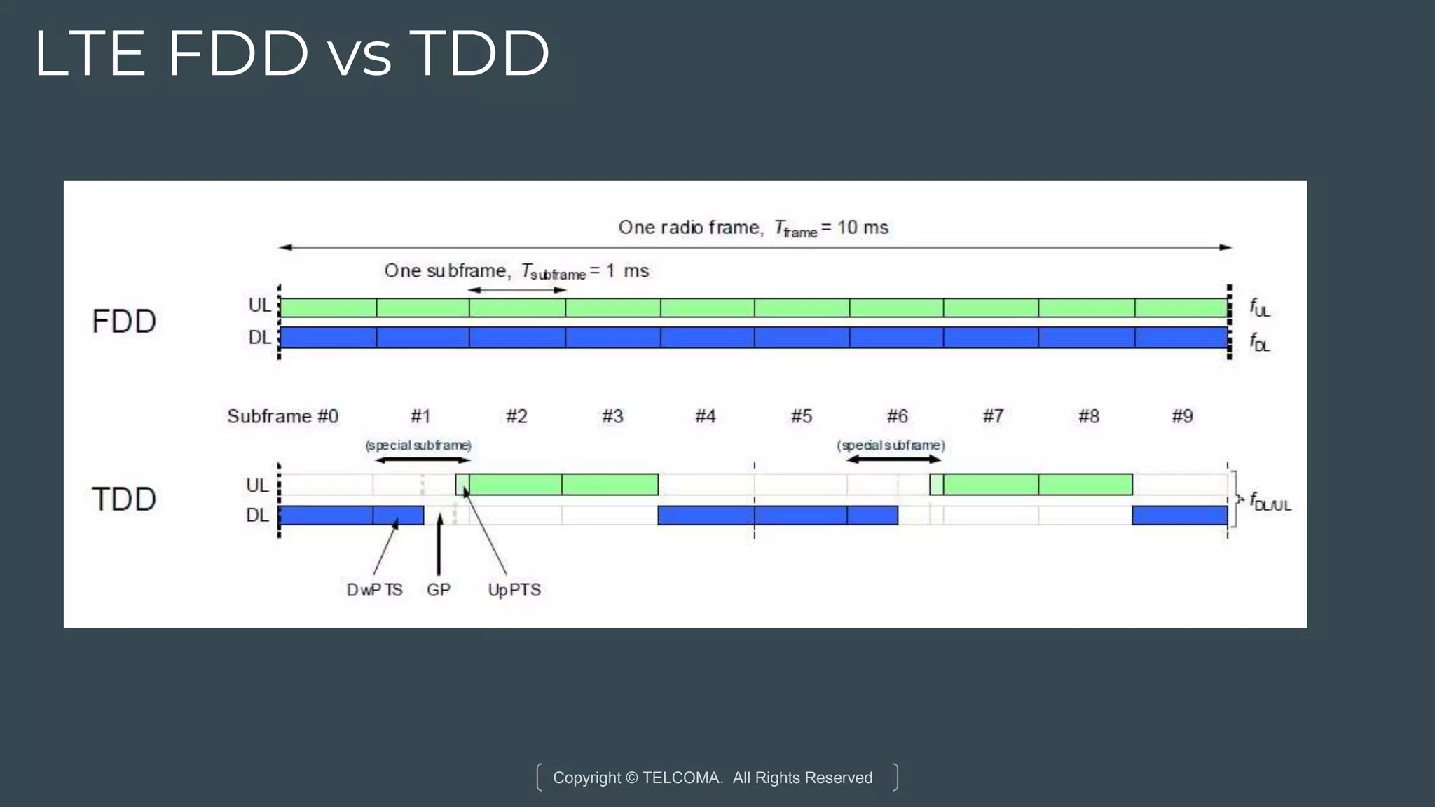
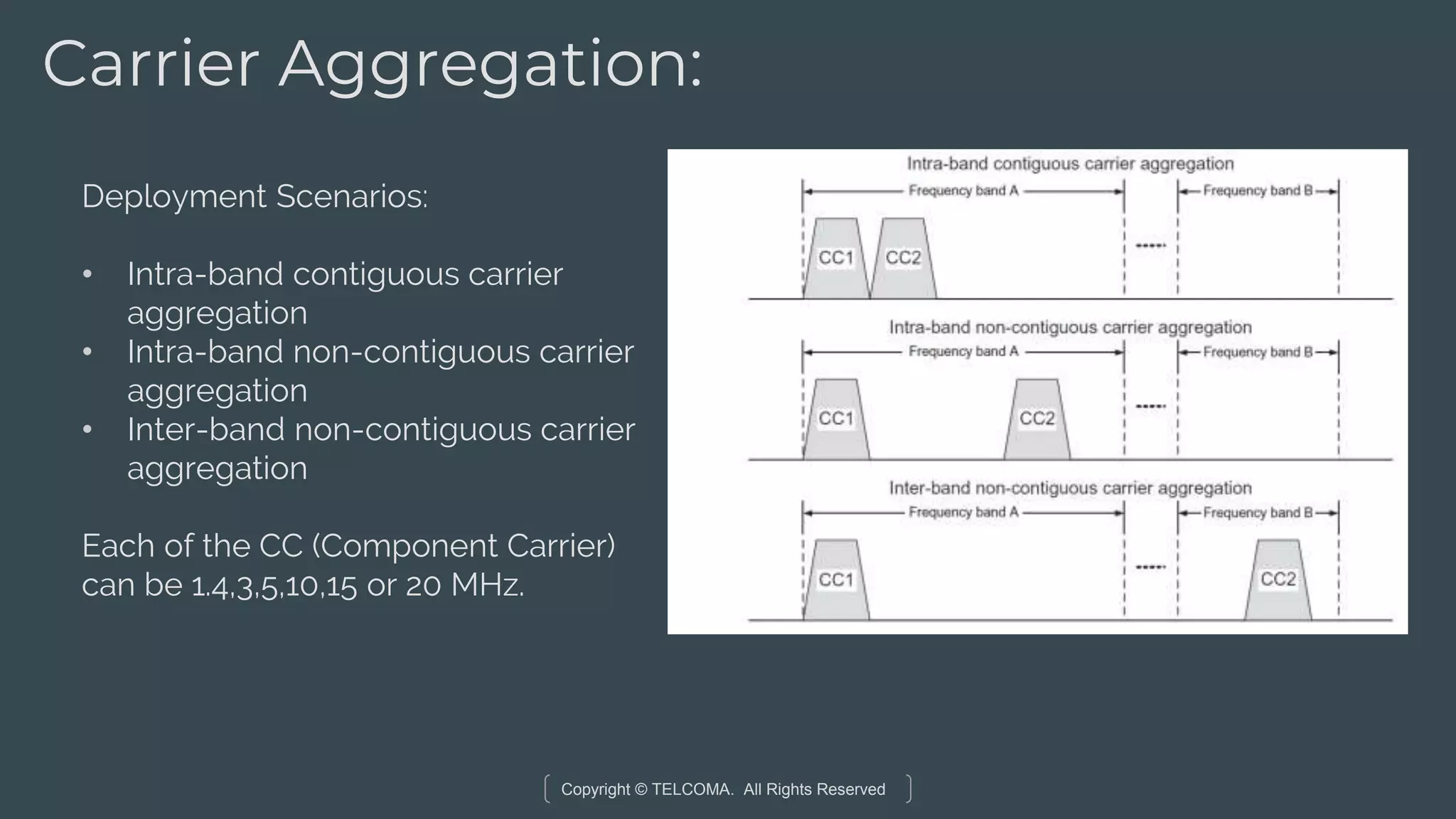
#62 CC is a component carrier
In FDD systems, a serving cell comprises a pair of
different carrier frequencies for downlink and uplink transmissions, whereas for
TDD, a serving cell is defined as a single-carrier frequency where downlink and
uplink transmissions occur in different transmission time intervals. Given that
component carriers do not have to be contiguous in frequency which enables
utilization of fragmented spectrum, operators with a fragmented spectrum can
provide high data-rate services based on the availability of a virtually wide
bandwidth even though they do not own a single wideband spectrum allocation.
#63 CC is a component carrier
In FDD systems, a serving cell comprises a pair of
different carrier frequencies for downlink and uplink transmissions, whereas for
TDD, a serving cell is defined as a single-carrier frequency where downlink and
uplink transmissions occur in different transmission time intervals. Given that
component carriers do not have to be contiguous in frequency which enables
utilization of fragmented spectrum, operators with a fragmented spectrum can
provide high data-rate services based on the availability of a virtually wide
bandwidth even though they do not own a single wideband spectrum allocation.
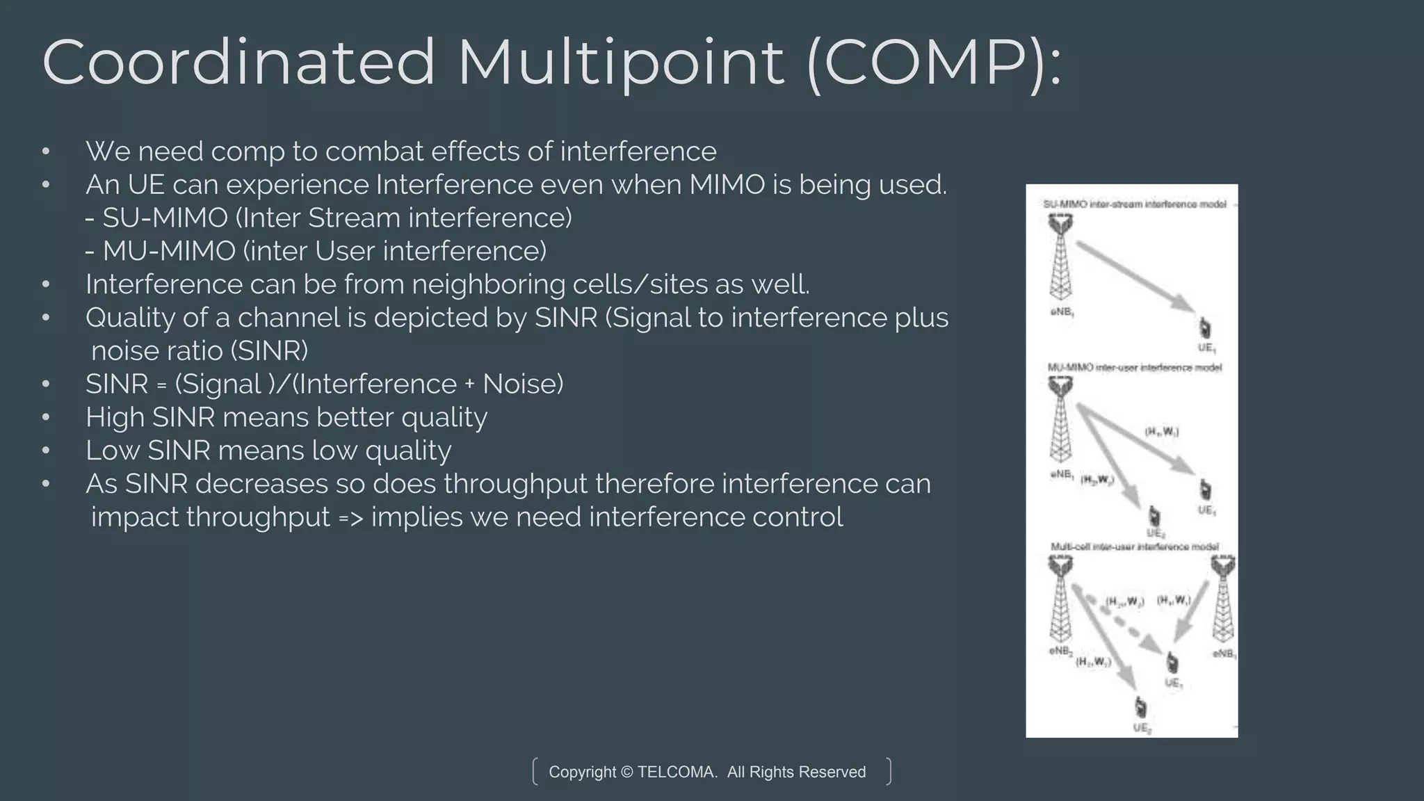
#64 Take a look at the different interference scenarios. Interference decrease SINR which leads to decrease in throughput. Coz of increase in BER
#65 Take a look at the different interference scenarios. Interference decrease SINR which leads to decrease in throughput. Coz of increase in BER
#66 Take a look at the different interference scenarios. Interference decrease SINR which leads to decrease in throughput. Coz of increase in BER
#67 Take a look at the different interference scenarios. Interference decrease SINR which leads to decrease in throughput. Coz of increase in BER