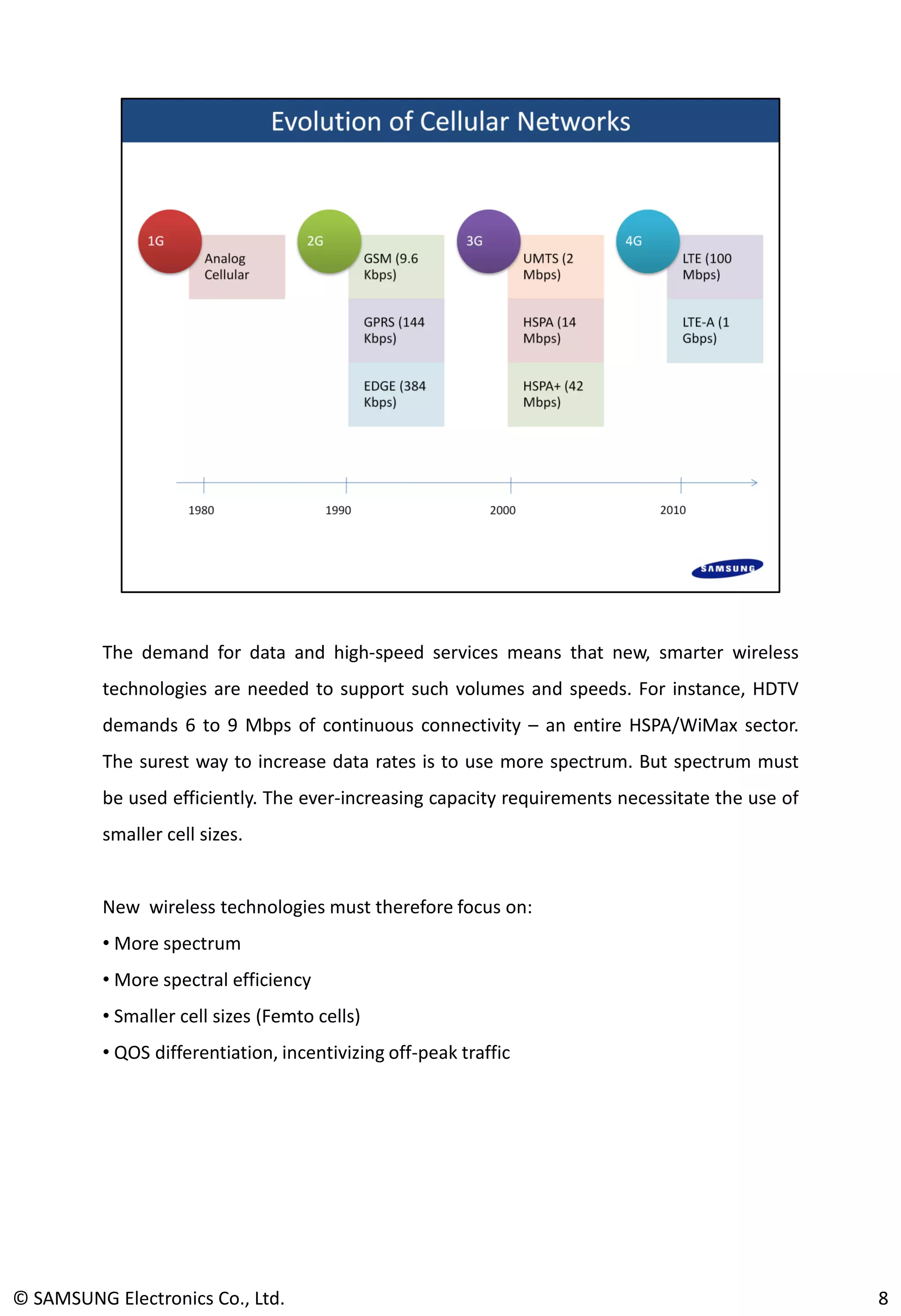
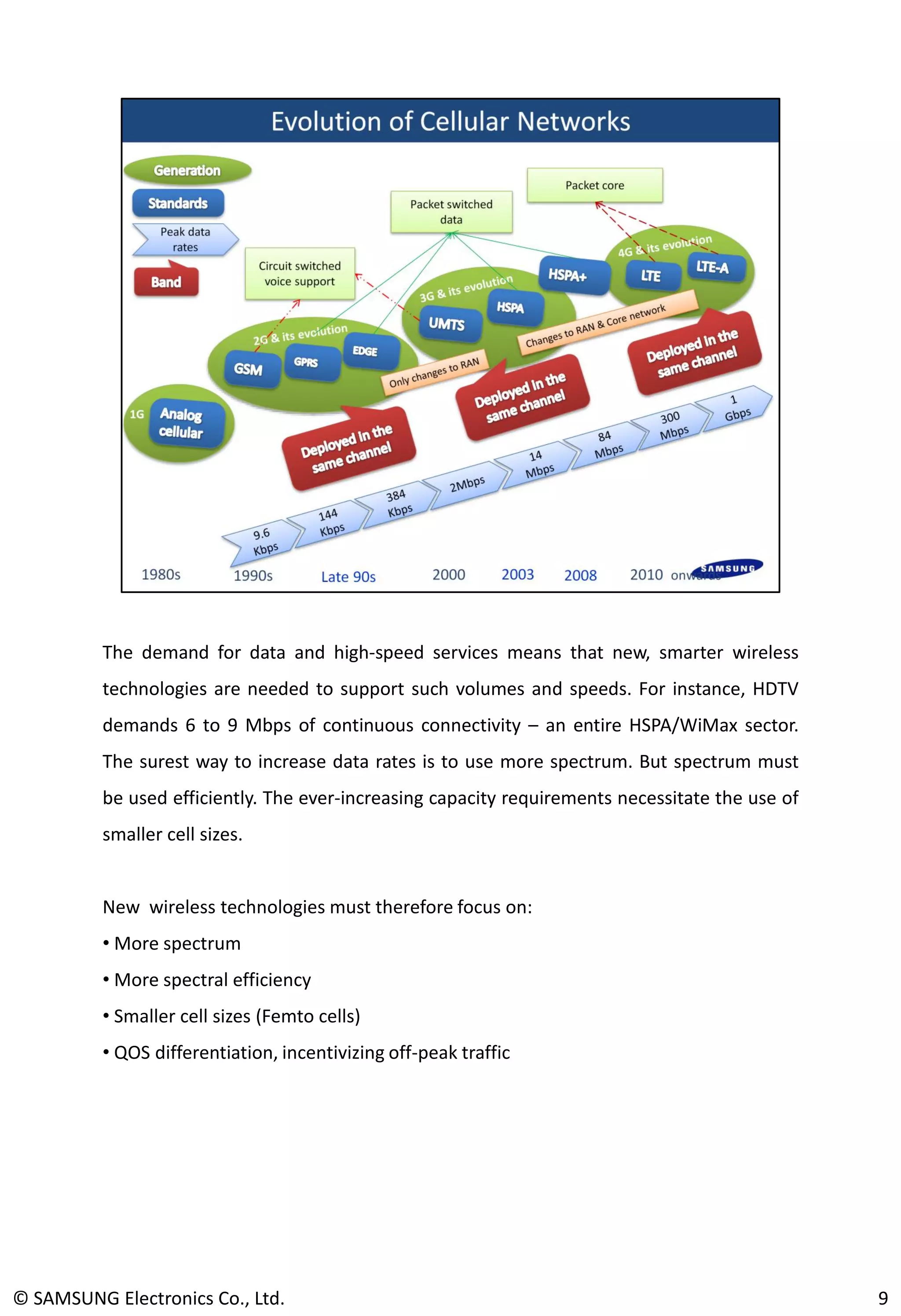
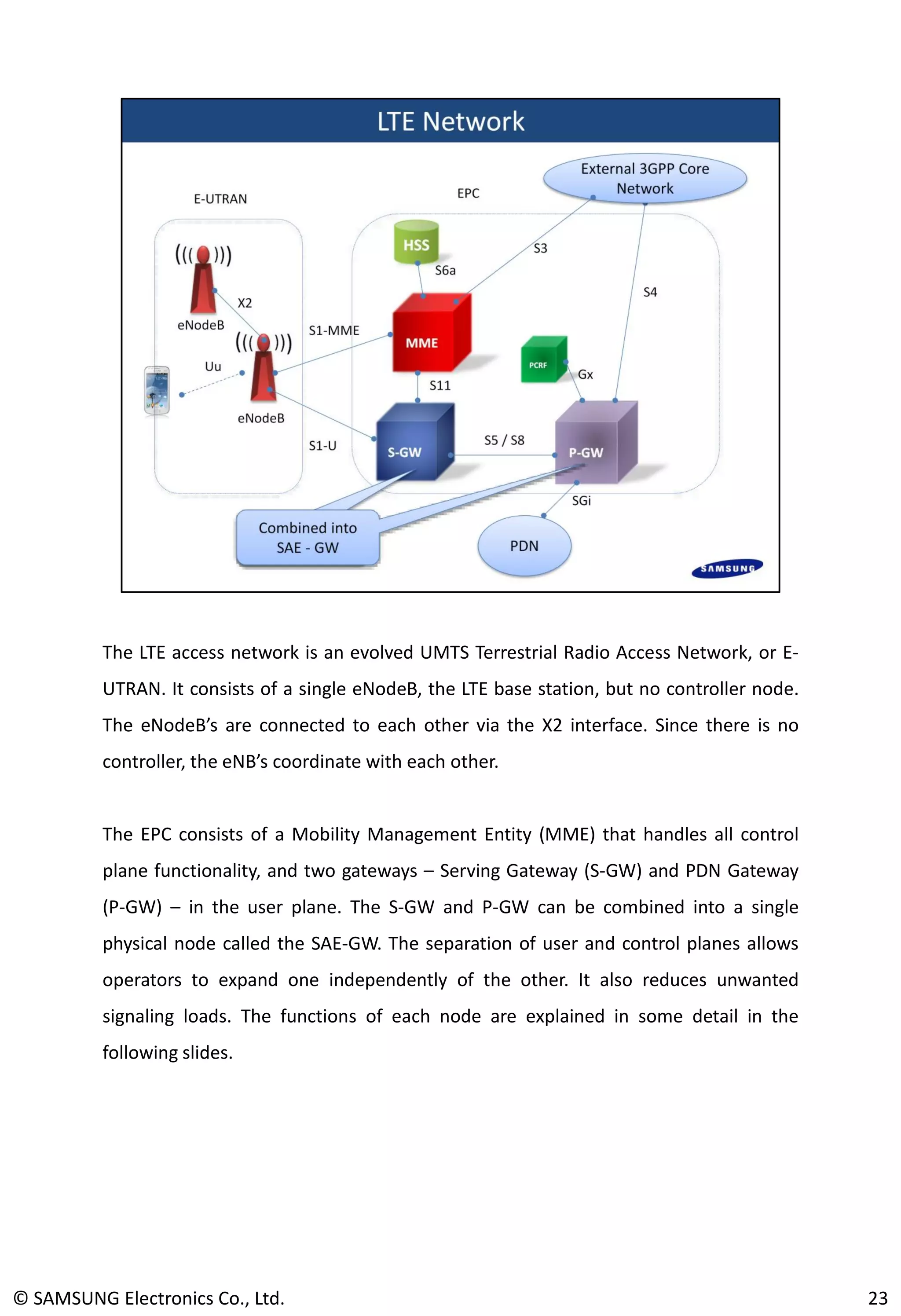
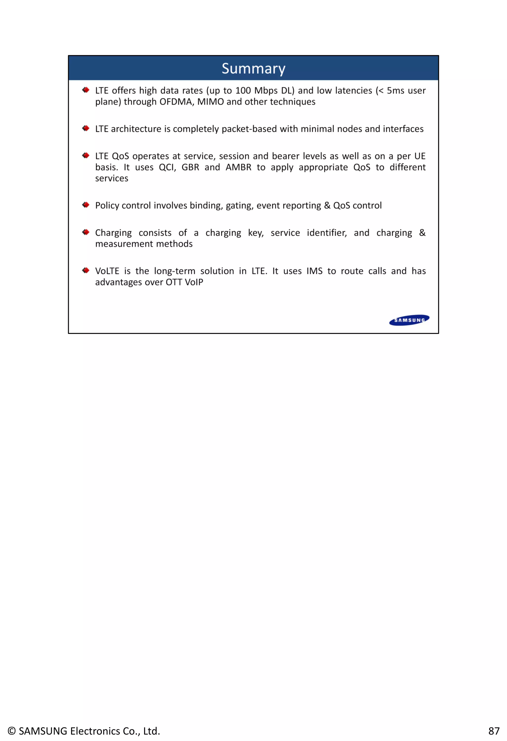
SlideShare a Scribd company logo
1
© SAMSUNG Electronics Co., Ltd. 2
© SAMSUNG Electronics Co., Ltd. 3
© SAMSUNG Electronics Co., Ltd. 4
© SAMSUNG Electronics Co., Ltd. 5
7© SAMSUNG Electronics Co., Ltd.
The demand for data and high-speed services means that new, smarter wireless
technologies are needed to support such volumes and speeds. For instance, HDTV
demands 6 to 9 Mbps of continuous connectivity – an entire HSPA/WiMax sector.
The surest way to increase data rates is to use more spectrum. But spectrum must
be used efficiently. The ever-increasing capacity requirements necessitate the use of
smaller cell sizes.
New wireless technologies must therefore focus on:
• More spectrum
• More spectral efficiency
• Smaller cell sizes (Femto cells)
• QOS differentiation, incentivizing off-peak traffic
8© SAMSUNG Electronics Co., Ltd.
The demand for data and high-speed services means that new, smarter wireless
technologies are needed to support such volumes and speeds. For instance, HDTV
demands 6 to 9 Mbps of continuous connectivity – an entire HSPA/WiMax sector.
The surest way to increase data rates is to use more spectrum. But spectrum must
be used efficiently. The ever-increasing capacity requirements necessitate the use of
smaller cell sizes.
New wireless technologies must therefore focus on:
• More spectrum
• More spectral efficiency
• Smaller cell sizes (Femto cells)
• QOS differentiation, incentivizing off-peak traffic
© SAMSUNG Electronics Co., Ltd. 9
Coordinated multipoint transmission and reception (CoMP)
© SAMSUNG Electronics Co., Ltd. 10
Shown above is a comparison between the LTE and GSM / WCDMA architectures.
LTE is a completely packet-switched network, requiring none of the costly circuit-
switched components that are necessary in earlier generations to support
conversational services.
The LTE access network consists of a single node, the eNodeB. There is no controller
equivalent of the BSC or RNC. This reduces the latency on the air interface,
significantly improving user experience.
In the LTE core, the user and control planes are separate. This further reduces
latency, eases signaling loads and allows operators to expand traffic capacity
independent of voice.
© SAMSUNG Electronics Co., Ltd. 11
Shown above is the timeline for important 3rd and 4th generation 3GPP releases
along with the key features in each release. R8 was the first LTE release where
OFDMA and the LTE core network were specified. R9 introduced Self-Organizing
Networks, discussed later, and LTE femtocells or home base stations. Femtocells are
very small cells with low transmit powers meant for homes or small offices. Release
10 introduces Co-operative Multi-antenna Processing (CoMP) which is a feature
where multiple eNodeB’s co-operate to transmit signals to cell-edge UE’s.
© SAMSUNG Electronics Co., Ltd. 12
Apart from the need for higher data rates, a major driver for LTE has been the need to
reduce network latencies. Packet-switched devices often lapse into a dormant state and
take some time to become fully active again. WCDMA and early HSPA releases suffered from
latency issues that hampered user experience. 3GPP has since paid special attention to this
issue. LTE requirements therefore clearly spell out the maximum allowable latencies in user
and control planes. Separating the user and control planes, and using IP-based ‘single node’
access and core networks help LTE reduce delays and improve user experience.
Control Plane  Transit time (RAN only) from non-active to active state. 100 ms for
transition from R6 Idle state, 50 ms for R6 Cell_PCH state. Related to this, 200 terminals in
active state should be supported in 5 MHz and 400 in wider deployments.
User Plane  Time to transmit small IP packet to / from RAN edge node measured on IP
layer. 5ms in unloaded network.
13© SAMSUNG Electronics Co., Ltd.
Unlike previous generations of cellular standards, LTE supports flexible bandwidth
deployment. LTE systems can use any of the bandwidths listed above. This allows
operators to deploy in a gradual manner, starting with lower bandwidths and
increasing the bandwidth as traffic grows. Deployments with different cell sites using
different bandwidths are also supported. This is particularly useful for high-capacity
hotspots and layering, i.e., micro or pico cells. LTE also supports both paired (FDD)
and un-paired (TDD) spectrum. RJIL will use TD-LTE.
14© SAMSUNG Electronics Co., Ltd.
Shown above are bands used by TD-LTE. There are regular additions to this list based
on ITU regulatory meetings. The 2.3 to 2.6 GHz bands are favored in Asia. Samsung /
RJIL will use the 2.3 GHz band.
© SAMSUNG Electronics Co., Ltd. 15
16© SAMSUNG Electronics Co., Ltd.
17© SAMSUNG Electronics Co., Ltd.
18© SAMSUNG Electronics Co., Ltd.
Before introducing the LTE network architecture, it’s worth re-visiting earlier
generations to get a sense of how the architecture has evolved. Shown above is a 2G
/ 2.5G GSM / GPRS architecture. The GSM, i.e., CS-voice part is handled by the Base
station Controller (BSC) and the Mobile Switching Center (MSC). The MSC is a switch
that connects to a Gateway-MSC (GMSC) which is plugged in to the landline PSTN.
With the introduction of GPRS, the first step toward packet switching was taken. The
Serving GPRS Support Node (SGSN) and the Gateway-GGSN (GGSN) form the packet
core of the GPRS / EDGE and early WCDMA releases. A Packet Controller Unit (PCU)
in the BSC split the traffic to the CS and PS core networks. Still, the CS core remains,
requiring huge investments in switching equipment and infrastructure.
© SAMSUNG Electronics Co., Ltd. 19
The WCDMA R99 architecture took some further steps towards independence of the
Radio Access Network (RAN) and the core. A Radio Network Controller (RNC) took
on some of the functions of the MSC. The inter-RNC interface was introduced in
order to support the CDMA soft handover feature. The base station was called
NodeB. Later releases, R5 HSDPA and above, made the NodeB capable of fast
dynamic scheduling but some of the more executive functions (e.g. admission
control) continued to rest with the RNC.
On the core side, there was little development in R99, largely to allow upgrades
using existing core networks. R4 did introduce the MSC Server or soft-switch and
Media Gateway (MGW) functionalities. This was the first time that control and user
planes were separated in the core. R5 allowed full IP Multimedia Subsystem (IMS)
support, an all IP network. Still, most operators continued to rely on CS core for
voice.
© SAMSUNG Electronics Co., Ltd. 20
The LTE access network is a single node RAN. The LTE base station, eNodeB, is
completely responsible for all the access functionalities. There is no controller node
analogous to the 2G Base Station Controller or the 3G Radio Network Controller. This
minimizes the number of interfaces required. In earlier generations, a failure in a
centralized controller for multiple base stations could potentially degrade service for
the entire area. LTE reduces such single-point failures.
The LTE network is completely packet-based end to end. No traffic is circuit
switched. LTE supports real-time conversational traffic by ensuring appropriate QoS
treatment for it. Every node in the LTE traffic path is QoS aware, making QoS an end-
to-end feature. Different QoS treatment is given to control, user and administrative
traffic.
21© SAMSUNG Electronics Co., Ltd.
Work on the LTE core was called System Architecture Evolution (SAE). The result was
an Evolved Packet Core (EPC). The LTE core is a single logical node, though the
control and user plane nodes are separate. Since IP is used end-to-end, it is often
referred to as a flat architecture.
EPC supports interworking with a wide range of other networks – GSM / GPRS,
WCDMA / HSPA, CDMA and WiFi – with appropriate interfaces defined for each
scenario. Since LTE is the technology of choice for both 3GPP and 3GPP2 operators,
interworking with both legacy cellular systems is a must. Initial LTE deployments are
usually in urban pockets. So most users will require handover to a legacy network
when they travel out of LTE coverage.
22© SAMSUNG Electronics Co., Ltd.
The LTE access network is an evolved UMTS Terrestrial Radio Access Network, or E-
UTRAN. It consists of a single eNodeB, the LTE base station, but no controller node.
The eNodeB’s are connected to each other via the X2 interface. Since there is no
controller, the eNB’s coordinate with each other.
The EPC consists of a Mobility Management Entity (MME) that handles all control
plane functionality, and two gateways – Serving Gateway (S-GW) and PDN Gateway
(P-GW) – in the user plane. The S-GW and P-GW can be combined into a single
physical node called the SAE-GW. The separation of user and control planes allows
operators to expand one independently of the other. It also reduces unwanted
signaling loads. The functions of each node are explained in some detail in the
following slides.
23© SAMSUNG Electronics Co., Ltd.
Being the single node in the E-UTRAN, the eNB performs all the Radio Resource
Management (RRM) functions. Thus it sets up radio bearers and admits or disallows
services based on the radio resource availability. An important function of the eNB is
to control mobility within the radio network. During handovers or cell reselection, it
coordinates with other eNB’s using the X2 interface to control user mobility. The eNB
is also responsible for dynamic radio resource allocation on the LTE time-frequency
resource grid. It handles scheduling of resources as well as paging and broadcast
functions. Encryption and header compression were carried out by controller nodes
in earlier generations, but they are done by the eNB in LTE.
An eNB is connected to one or more MME’s via the S1-MME interface. When a user
attaches to the network, the eNB must select an MME from an MME-pool. It sends
signaling information such as measurements and messages to the MME.
24© SAMSUNG Electronics Co., Ltd.
Universal platform type A Management board Assembly
LTE eNB Channel card board Assembly
Shown above are the Samsung Digital Unit (DU) and Remote Radio Unit (RRU). The
DU is installed in a cabinet at the bottom of the tower or the rooftop floor. It consists
of a UAMA board, which is the controller, and an L9CA board which is the channel
card. A single L9CA board can support up to 3 sectors.
The RRU is installed close to the antenna. The two are connected using an optical
cable. This minimizes losses along the length of the tower and allows high data rate
information exchange.
© SAMSUNG Electronics Co., Ltd. 25
© SAMSUNG Electronics Co., Ltd. 26
© SAMSUNG Electronics Co., Ltd. 27
Channel-dependent scheduling is an important aspect of an LTE eNB. Radio
conditions within the cell vary with time and location. The eNB scheduling
mechanism exploits this by preferentially scheduling UE’s in better radio conditions
while keeping a fair amount of resources for UE’s in bad radio conditions, thereby
improving throughput and quality.
Since LTE radio resources are basically frequencies, one of the key challenges in LTE
networks is managing inter-cell interference. Neighboring NB’s can operate on the
same bandwidths. Some co-ordination is therefore required to reduce interference
in the network. The Samsung Smart Scheduler Server addresses this problem by
providing UL & DL co-ordination among the eNB’s it controls. It constantly keeps
eNB’s informed of neighbor resource allocations, so that their own allocations can
minimize inter-cell interference. This results in increased cell-edge throughput.
Additionally, the Smart Scheduler also provides O&M functionalities.
© SAMSUNG Electronics Co., Ltd. 28
The MME is the heart of the EPC as far as signaling is concerned. It is responsible for
the setup and management of bearers, or logical connections, with the user. When
user equipment (UE) is idle, the MME needs to generate a paging message to reach
the UE. This means that the MME must have some idea of the UE location. So the UE
updates the MME of change in location at suitable times. The MME is also
responsible for authentication.
Since it does setup, the MME is responsible for selecting gateways for user plane
traffic. This could be based, for example, on load considerations. The MME also has
an S3 interface to connect with other 3GPP core networks, e.g. to an SGSN. When a
user travels out of LTE coverage into 2.5/3G coverage, the MME can select the
appropriate SGSN. Within an LTE network, inter-MME mobility is handled via the S10
interface. The MME checks authorization and roaming issues via S6a, its interface to
the Home Subscriber server (HSS). It also supports lawful intercept for signaling
messages.
29© SAMSUNG Electronics Co., Ltd.
The Samsung MME offers high reliability and capacity. It supports mobility
management functions such as tracking area updates, paging and handover. It can be
co-located with the S-GW and the P-GW.
The MME consists of three kinds of cards:
LEMA: The LTE EPC Management Board Assembly consists of the switch and the
management functionality.
LENA: All external connections to the MME terminate on the LTE EPC Network
Assembly board.
LESA: The core MME functionality resides in the LTE EPC Session management board
Assembly.
Samsung MME supports high redundancy. The LEMA and LENA boards support 1:1
redundancy, while the LESA board operates in 2:1 redundancy mode.
© SAMSUNG Electronics Co., Ltd. 30
The S-GW is the local mobility anchor. It is analogous to the 2G SGSN. It ‘anchors’ the
UE data connection during inter-eNB handovers. Packets may arrive for the UE when
it is idle. The S-GW then buffers them until the UE is active and ready to receive data.
It also initiates a network triggered service request in such cases. Besides, the S-GW
can also handle handovers to other 3GPP networks via the S4 interface. It facilitates
re-ordering of packets by sending an “end marker” to the eNB or source SGSN / RNC
after handover.
The S-GW helps in inter-operator charging via the S5 / S8 interface to the P-GW. It
supports transport level QoS functions such as IP Differentiated Services and
supports lawful interception of data packets.
A UE has one and only one S-GW at a time.
31© SAMSUNG Electronics Co., Ltd.
The P-GW is the EPC entry and exit point for packets to travel in and out of the LTE
network. It is analogous to the GGSN. Thus, the P-GW is connected to the external
Packet Data Network (PDN), for example the Internet, and to all other external
networks such as 3GPP, 3GPP2.
The P-GW allocates IP addresses to UE’s and performs all the policy control and
charging related functions. Naturally, it also performs DHCP functions. It plays an
important role in QoS and also supports IP Differentiated Services. The S-GW and P-
GW can be and often are combined into one physical node, called the SAE Gateway.
© SAMSUNG Electronics Co., Ltd. 32
The Samsung SAE-GW supports P-GW functionalities such as Policy & Charging
Enforcement Function (PCEF). User and service based QoS control as well as flow
based charging are supported. In addition advanced features such as Deep Packet
Inspection (DPI) and HTTP Header Enhancement (HHE) are also supported. DPI refers
to the opening of a packet all the way up to the application layer, allowing operators
to monitor services. HHE refers to enhancements to the HTTP protocol header
allowing the operator to provide subscriber information (e.g. IMSI) to application
servers.
The LEMA and LENA cards have the same functions as in the MME. The LTE EPC Data
Processing Assembly (LEDA) performs the core SAE-GW functions of the user plane.
© SAMSUNG Electronics Co., Ltd. 33
Shown here is a schematic of the RJIL 4G network deployment. Different levels of
Aggregation routers (AG’s) are deployed. Each eNodeB is connected via backhaul to
an Aggregator node, AG1. An AG1 pair (for redundancy) consists of 4 rings with 5
eNodeB’s per ring, i.e., a total of 20 eNB’s per AG1 pair. 10 AG1 rings (up to 4 AG1’s
per ring) connect to the AG2 level. The centralized scheduler is located at the AG2
level. Finally, an AG3 node supports 16 AG2 pairs. The EPC and IMS nodes are
deployed at the AG3 level.
© SAMSUNG Electronics Co., Ltd. 34
The RJIL plan consists of 18 EPC’s for 22 circles. These 18 EPC’s are managed by one
of 4 regions – north, south, east and west. While each circle will have a Media
Gateway (MGW), most of the core IMS nodes will be deployed at the regional level.
At the highest level are 2 zones – Mumbai for the West and South zones, and Delhi
for the North and East zones. High level functionalities such as IMS applications, OSS
and billing will reside at the zones.
© SAMSUNG Electronics Co., Ltd. 35
© SAMSUNG Electronics Co., Ltd. 36
© SAMSUNG Electronics Co., Ltd. 37
38© SAMSUNG Electronics Co., Ltd.
Spectrum is a scarce and costly resource. Continually increasing the spectrum cannot
be the only way to obtain high data rates. Cellular systems therefore rely on other
techniques to increase data rates:
• Link Adaptation: Modifying link transmission parameters to handle variations in
radio link quality. A well known example is Adaptive Modulation and Coding (AMC),
where UE’s in good radio conditions are given better data rates by modifying the
modulation and coding used
• Channel-dependant Scheduling: Minimize the amount of resources used keeping
the required QOS in mind
• Hybrid ARQ: Transmitters add redundant bits to the data (precaution before
transmission) and receivers request retransmission of erroneously received data
(improvement after transmission)
• Multiple Antennas: Diversity, beam-forming, MIMO
39© SAMSUNG Electronics Co., Ltd.
Multiple Input Multiple Output (MIMO) refers to the use of multiple antennas on the
transmit and receive side. It was first introduced in HSPA+, but has been part of LTE
since R8. In fact one of the strengths of OFDMA compared to WCDMA is that it
makes MIMO implementation feasible. MIMO is a general term often used to
describe two possibilities. The first one is Spatial Multiplexing, wherein two data
streams are sent on two antennas simultaneously, thereby increasing data rates. This
is typically used for UE’s in good radio conditions. It is often described as N x M
MIMO, where N is the number of transmitters and M the number of receivers.
Typical values are 2 x 2 and 4 x 4.
For UE’s that are at the cell-edge, the dominant problem is poor signal quality due to
interference. In this case, two copies of the same information can be sent to the UE.
This is Transmit Diversity and it helps reduce the interference experienced by the UE
.
© SAMSUNG Electronics Co., Ltd. 40
LTE uses Orthogonal Frequency Division Multiple Access (OFDMA). The total carrier
bandwidth is divided into mutually orthogonal sub-carriers of fixed width – 15 KHz.
The small sub-carrier spacing implies large bit periods, making OFDMA robust
against multipath. This multiple access technique allows for allocation of different
bandwidths to different services.
The sub-carriers are orthogonal because the LTE pulse is designed so that, in
frequency domain, the peak power of one sub-carrier coincides with zeroes of all the
other sub-carriers as shown above. One can imagine a large number of finely tuned
radio stations transmitting simultaneously without interfering with each other. A
single OFDM symbol is constructed by parallel transmission of multiple sub-carriers
during a symbol time interval. A single sub-carrier during one OFDM symbol is called
a Resource Element (RE). This is the smallest physical resource in LTE.
© SAMSUNG Electronics Co., Ltd. 41
Along with OFDMA, LTE also uses fast (of the order of 1ms), dynamic time-domain
scheduling done at the LTE base station, called the eNodeB. This allows for a highly
flexible allocation of radio resources on a time-frequency grid as shown above. The
basic unit of allocation is a Resource Block (RB) consisting of 12 sub-carriers (12 x 15
= 180 KHz) and a single time slot, 0.5 ms.
The fact that radio resources are managed completely by the eNodeB makes LTE a
single-node access network, reducing latencies and improving throughputs.
42© SAMSUNG Electronics Co., Ltd.
A problem with OFDMA systems is the high Peak-to-Average Power Ratio (PAPR).
The transmitted power in OFDM is the sum of the powers of all the subcarriers. Due
to large number of subcarriers, the peak to average power ratio (PAPR) tends to have
a large range. The higher the peaks, the greater the range of power levels over which
the power amplifier is required to work. This is a problem for use with mobile
(battery-powered) devices.
A new, OFDMA-based scheme called single carrier frequency division multiple access
(SC-FDMA) was developed for the LTE uplink. By restricting uplink transmissions to
smaller, contiguous parts of the carrier, SC-FDMA enables a lower UE peak-to-
average power ratio (PAPR) which eases amplifier design in the mobile devices.
43
Shown above is a time-frequency view of OFDMA and SC-FDMA. As can be seen,
OFDMA sends one modulation symbol on one sub-carrier in one symbol duration.
SC-FDMA sends one modulation symbol on N sub-carriers (4 in the above example)
in 1/Nth symbol duration. The number of sub-carriers N depends on the bandwidth
allocated to the UE.
44
© SAMSUNG Electronics Co., Ltd. 45
© SAMSUNG Electronics Co., Ltd. 47
48© SAMSUNG Electronics Co., Ltd.
© SAMSUNG Electronics Co., Ltd. 49
The LTE UE is a stand alone device performing all the functions that are performed in
the network. At the lowest physical layer, it encodes and decodes data, performs
OFDM, modulation and demodulation, as well as supports multiple receive /
transmit. The UE updates the network of its location and sends measurements to
allow the network to make informed decisions, especially for handovers. The UE
must setup, maintain and teardown IP sessions with the LTE network. It must also
keep a record of the identities given to it by the eNB and the EPC.
© SAMSUNG Electronics Co., Ltd. 50
LTE UE categories define the standards by which a particular handset, dongle or
other equipment will operate. Based on their maximum data rates and number of
multiple transmit / receive antennas, UE’s are assigned categories. Shown above are
the R8 / R9 UE categories.
There are five different LTE UE categories defined. As can be seen in the table above,
the different LTE UE categories have a wide range in the supported parameters and
performance. LTE category 1, for example does not support MIMO, but LTE UE
category five supports 4x4 MIMO. Note that despite supporting the same
modulation and MIMO, categories 2,3 and 4 support different maximum data rates.
This is because they differ in the number of maximum bits they can decode in each
TTI.
It is also worth noting that UE class 1 does not offer the performance offered by that
of the highest performance HSPA category. Additionally all LTE UE categories are
capable of receiving transmissions from up to four antenna ports.
51
© SAMSUNG Electronics Co., Ltd. 52
PoC: Push to talk over cellular
Different services have different requirements of the network. Quality of Service
(QoS) is a way to differentiate between services based on these requirements so that
the network can serve users better. Shown above are some typical services used on
cellular networks. Each of these has its own QoS requirements. Generally, QoS is
understood in terms of three key factors: bit-rate, delay and error. Services are then
categorized based on their requirements of these three. For instance, real-time (RT)
services are strict about delay. If the RT service happens to be video, it also requires
high data rate and has low tolerance for errors. Web-browsing, on the other hand,
can tolerate some delay but is strict about error rates.
Since LTE supports a wide variety of services, it needs to have a QoS mechanism in
place to satisfy service requirements.
53© SAMSUNG Electronics Co., Ltd.
Before discussing the LTE QoS mechanism, it is important to understand bearers. A
bearer is essentially a logical connection that carries some data. The UE is logically
connected to different entities in the LTE network. With the E-UTRAN (i.e. eNB), the
UE has a radio bearer. With the EPC, the UE is connected to the P-GW via an EPS
bearer that is used to carry IP traffic with a certain QoS. Each EPS bearer is
associated with a set of QoS parameters.
A PDN connection is the IP session link between the UE and the external data
network (e.g. the internet). This is the level at which the UE is known by an IP
address. All EPS bearers belonging to one PDN connection share the same IP
address. While a PDN connection is equivalent to a session, in 2G terms, an EPS
bearer is equivalent to a PDP context.
54© SAMSUNG Electronics Co., Ltd.
When a UE first attaches to the network and establishes a new PDN connection, LTE
sets up a Default Bearer that remains active for the lifetime of that connection. A
Default Bearer is essentially a way to provide always on connectivity. Recall that
packet switched user devices frequently go into dormant modes. Having a Default
Bearer is a way to minimize the signalling required to start data transfer when
coming out of inactivity. This helps LTE achieve low signalling latencies.
Depending on services that the UE requests, a Dedicated EPS bearer may be set up.
This is essentially demand based. Since the Default bearer is associated with a set of
QoS parameters, any service that has different QoS requirements may require a
Dedicated Bearer.
From the QoS perspective, bearers can be Guaranteed Bit Rate (GBR) or non-GBR. A
GBR bearer is a way to commit a certain bit rate to the user. Default bearers are
always non-GBR. Dedicated bearers can be GBR or not, depending upon the service
QoS.
55© SAMSUNG Electronics Co., Ltd.
SDF: An aggregate set of packet flows that matches a set of filters.
http://wired-n-wireless.blogspot.in/2010/09/sdf-qci-and-dedicated-bearers.html
Since QoS is essentially a function of the service or application being invoked by the
user, LTE uses the notion of a Service Data Flow (SDF). An SDF is basically a set of IP
flows corresponding to a service. The P-GW receives IP flows from an external PDN
and performs Filtering, i.e., maps these IP flows to SDF’s. Each SDF corresponds to a
particular QoS treatment applied by the Policy Control & Enforcement Function
(PCEF), which is a P-GW functionality. An SDF thus corresponds to a QoS treatment.
An SDF aggregate is a combination of one or more IP flows. Since an SDF
corresponds to a QoS treatment and so does an EPS bearer, it follows that an EPS
bearer can carry only one SDF aggregate, i.e., QoS treatment remains the same
within a bearer. This is how the LTE network maps services to bearers based on QoS.
© SAMSUNG Electronics Co., Ltd. 56
QCI- QoS Class Identifier
QoS in LTE networks operates at different levels. At the service level SDF’s are used
to apply QoS and other policies such as traffic conditioning to the IP flows. At the
session level, QoS is based on Access Point Names (APN’s) defined in P-GW. APN’s
correspond to the external network path that the P-GW will use for the service (e.g.
voice APN, Mobile TV APN). Typically, an APN will consist of multiple bearers. For
non-GBR bearers, the network uses an Aggregate Maximum Bit Rate (AMBR) to
enforce QoS. As the name suggests, AMBR regulates the total maximum bit rate of
multiple bearers set up on a given APN.
At the bearer level, the policy uses Binding. Binding essentially ties a bearer to a
Quality Class Indicator (QCI), which is a numeric value for QoS class. QCI is discussed
in the next slide.
Finally, at the UE level, similar to an APN, a per-UE AMBR is used to regulate the
QoS. Since the radio resource allocation and scheduling are done by the eNB, UE
level QoS is enforced by the eNB.
© SAMSUNG Electronics Co., Ltd. 57
The QCI is a scalar mapping of a set of transport characteristics - bearer
with/without guaranteed bit rate, priority, packet delay budget, packet error loss
rate. It is used to infer node-specific parameters that control packet forwarding
treatment, e.g., scheduling weights, admission thresholds, queue management
thresholds, link-layer protocol configuration, etc.
Each packet flow is mapped to a single QCI value. 9 QCI levels are defined in the
Release 8 version of the specifications according to the level of service required by
the application. Each QCI implies a Packet Delay Budget (PDB) between the UE and
P-GW and a Packet Error Loss Rate (PELR).The QCI, together with Allocation-
Retention Priority (ARP) and, if applicable, Guaranteed Bit Rate (GBR) and Maximum
Bit Rate (MBR), determines the QoS associated with an EPS bearer.
© SAMSUNG Electronics Co., Ltd. 58
© SAMSUNG Electronics Co., Ltd. 60
© SAMSUNG Electronics Co., Ltd. 61
© SAMSUNG Electronics Co., Ltd. 62
Shown above are the key players in the PCC architecture.
PCRF: The Policy & Charging Rules Function decides on polices and charging based
on flows and conveys these decisions to the PCEF.
PCEF: The Policy & Charging Enforcement Function, residing in the SAE-GW, enforces
policies such as gating and QoS control on behalf of the PCRF.
BBERF: The Bearer Binding & Event Reporting Function, also in the SAE-GW, binds a
service flow to an IP bearer (in effect a QoS). It also reports events such as request
for a new service, especially to charging systems.
SPR: The Subscriber Profile Repository provides subscriber specific data to the PCRF
to assist in evaluating policy decisions.
AF: The Application Function represents applications, i.e., it provides application
level information to the PCRF assisting the PCRF in policy decision making.
The Gx, Rx and Sp interfaces are Diameter based.
© SAMSUNG Electronics Co., Ltd. 63
The PCC functions just discussed are performed based on Rules. A PCC Rule is
essentially a concise way to detect SDF’s and capture PCC parameters for the PCEF to
enforce. An SDF can be identified by a flow descriptor, a 5-tuple consisting of the
source and destination IP and port addresses and the protocol type being used. The
protocol type and port are usually good indicators of the nature of the service and
can be used to give it a certain QoS treatment.
© SAMSUNG Electronics Co., Ltd. 65
PCC Rules are broadly of two kinds. A Dynamic Rule, as the name suggests, can
change. Its definition comes to the P-GW from the Policy Control and Resource
Function (PCRF) via the Gx interface between the two. A Pre-Defined Rule, on the
other hand, is provisioned directly into the PCEF by the operator. Dynamic rules
allow adaptation to changes in traffic, for instance, a new service type.
© SAMSUNG Electronics Co., Ltd. 66
Shown here is an example of policies applied to flows. The PCEF filters IP flows by
applying SDF templates, resulting in the grouping of IP flows into SDF’s. Then, using
policy rules, a policy is applied to each SDF. This covers QoS, charging and other
aspects of the service.
© SAMSUNG Electronics Co., Ltd. 67
Like policy rules, charging has its own components. A Charging Key is used for an SDF
to determine the tariff to be applied to it. A Service Identifier establishes the identity
of the service or service component that the SDF in a rule relates to. This identifier
can then be used to support Flow-Based Charging. Thus, a users transactions on a
banking website are charged differently than streaming content.
An important consideration is whether charging is offline or online, or in fact the
service is free of charge. Also important is the method to measure usage – it can be
based on volume (e.g. per MB), duration (e.g. per unit time), a combination of the
two, or an event (e.g. activation).
© SAMSUNG Electronics Co., Ltd. 68
Charging systems are broadly either Offline (OFCS) or Online (OCS). OCS’s can affect
services in real-time, especially important for pre-paid services. OFCS’s work offline
in the background, based on billing plans and billing cycles.
OCS (online charging system) provides credit management and grants credit to the
PCEF based on time, traffic volume or chargeable events.
OFCS (off-line charging system) receives events from the PCEF and generates
charging data records (CDRs) for the billing system.
© SAMSUNG Electronics Co., Ltd. 69
© SAMSUNG Electronics Co., Ltd. 70
© SAMSUNG Electronics Co., Ltd. 71
© SAMSUNG Electronics Co., Ltd. 72
An important development in the 3GPP cellular standards is the introduction of Self-
Organizing Networks (SON’s) in R8. Cellular networks have increased in complexity.
Multiple technologies, heterogeneous networks (i.e. macro, micro, pico and femto
cells), multiple vendors and multiple services in 3G and 4G make optimization that
much harder. SON’s address these issues.
Broadly, the processes taken on by SON fall under the two categories shown above.
Routine or repetitive processes such as configuration can be streamlined by
automating them. This leads to reduced OPEX and faster deployments. There may be
processes that are good candidates for automation because they are too fast or too
‘fine’ (e.g. per user, per flow) for manual intervention. Measurements from various
network devices, monitoring tools and users, along with algorithms that react to
these measurements can improve network performance. Such improvements (e.g.
adding of a missing neighbor) can happen fast, in near real-time, not being
dependent on manual intervention. They also Minimize Drive Testing (MDT), a costly
and time consuming exercise.
© SAMSUNG Electronics Co., Ltd. 73
Shown here is a high-level view of the Samsung eNodeB self-configuration
mechanism. Samsung eNB’s support plug-and-play with IPV6.
1) The eNB detects an open port and acquires the eNB IP and the Samsung LTE
System Manager (LSM) IP addresses from the DHCP server on the universal OAM
VLAN.
2) Next, it connects to the LSM and gets the software image and configuration from
the LSM.
3) Once it has its configuration, the eNB now sets up two additional VLAN’s – one
for the S1-Control plane connection with the MME and a second one for the S1-
User plane and X2 interfaces with the SAE-GW and neighboring eNB’s,
respectively.
© SAMSUNG Electronics Co., Ltd. 74
4) On the VLAN for S1-C, the eNB establishes an S1-C connection with the MME.
5) On the S1-u and X2 VLAN, it establishes the S1-U connection with the SAE-GW.
6) If it has a Neighbor Relations Table, the eNB then establishes X2 connections
with neighboring eNB’s on the S1-U and X2 VLAN.
© SAMSUNG Electronics Co., Ltd. 75
The Samsung Automatic Neighbor Relations (ANR) functionality begins at
deployment of the eNB. During the initial configuration, as discussed earlier, the eNB
obtains a Neighbor Relations Table (NRT) from the LSM. Based on this, it sets up X2
connections with its defined neighbors.
Once operational, the Samsung eNB also performs self-optimization. This can be UE-
based, wherein the UE assists in obtaining neighboring cell information by reporting
it to the LSM. If such reporting is unavailable, the network, via the LSM, itself
recommends the identity and IP address of the neighbor. Based on handover
statistics, the Samsung eNB can rank as well as remove neighbors.
© SAMSUNG Electronics Co., Ltd. 76
© SAMSUNG Electronics Co., Ltd. 77
Earlier cellular generations used circuit-switched core networks for voice. LTE,
however, is completely packet-based. The routing of voice traffic in LTE therefore
requires approaches that are different from the earlier generations. Shown above
are two approaches to voice in LTE.
Circuit Switched Fallback simply leans on the earlier networks (2G / 3G) to handle
voice. As such, it is a temporary fix, typically used during early stages of deployment.
Voice over LTE, or VoLTE, uses the IP Multimedia Subsystem (IMS) network to offer
completely packet-switched voice to LTE users. This is the long-term solution for
voice. Another term often used in the literature is Single Radio Voice Call Continuity
(SR-VCC). ‘Single radio’ refers to the VoLTE advantage that the UE doesn’t have to
switch radios when making a voice call. ‘Continuity’ refers to the feature that when
an LTE user on a voice call moves out of LTE coverage, the handover to 2G / 3G
should be seamless.
© SAMSUNG Electronics Co., Ltd. 78
Shown above is a view of the IP Multimedia Subsystem architecture and its
interfaces with the EPC. The signaling protocol used for VoIP is Session Initiation
Protocol (SIP). Below is a brief description of each node.
P-CSCF: The Proxy Call Session Control Function handles bearer establishment and
related functions. Being a proxy, it is the first point of contact for an IMS user device.
S-CSCF: The Serving CSCF holds user-specific data such as details of some services
etc., downloaded from the HSS. It terminates call/session signaling from UE and
interacts with the application & services area.
I-CSCF: Interrogates the HSS for calls terminating on the UE to determine which S-
CSCF will cater to the UE.
BGCF: Breakout Gateway Control Function is a SIP proxy that processes routing
requests from S-CSCF based on telephone numbers.
© SAMSUNG Electronics Co., Ltd. 79
MGCF: Media Gateway Control Function controls the Media Gateway (MGW) using
the H.248 protocol. The MGW forms the media plane while the MGCF is the
signaling plane. The MGCF translates from SIP (packet switched) to ISUP (circuit
switched) and communicates with the PSTN via a Signaling Gateway (SiGW). The
MGW translates from RTP (Real-Time Transport Protocol) to circuit switched voice
(e.g. AMR).
MRFx: The Media Resource Function (MRF) provides media functionalities and is
also split into the Media Resource Function Control (MRFC) which forms the
signaling plane and the Media Resource Function Part (MRFP) which is the media
plane. The MRFC interprets signaling from the S-CSCF, while the MRFP processes
media.
Application Environment: The application servers consist of the Voice Call Continuity
(VCC), the Rich Communications Suite (RCS) and the Telephony Application Services
(TAS) servers.
© SAMSUNG Electronics Co., Ltd. 80
Shown above is an overview of the steps involved in UE registration with the IMS.
© SAMSUNG Electronics Co., Ltd. 81
Shown above is a step by step overview of the VoLTE call setup using IMS.
© SAMSUNG Electronics Co., Ltd. 82
A natural question about VoLTE is what are its advantages over applications that
already provide VoIP services. First, VoLTE is more QoS aware. This means that it
enables prioritization of voice over other data by using the LTE QoS classes. Over the
Top (OTT) VoIP treats voice like any other data stream.
Secondly, VoLTE being native to the handset can leverage some of its capabilities
such as wideband codecs and dual microphone to enhance audio perception. It can
also use the native address book to offer Rich Communication Suite (RCS) services
such as Presence. Such advantages are not available to OTT VoIP.
© SAMSUNG Electronics Co., Ltd. 84
© SAMSUNG Electronics Co., Ltd. 85
© SAMSUNG Electronics Co., Ltd. 86
© SAMSUNG Electronics Co., Ltd. 87
© SAMSUNG Electronics Co., Ltd. 88

More Related Content

What's hot

Lte drive test parameter introduction
Lte drive test parameter introductionLte drive test parameter introduction
Lte drive test parameter introduction
Ray KHASTUR
 
Top 10 3 G Radio Optimisation Actions
Top 10 3 G Radio Optimisation ActionsTop 10 3 G Radio Optimisation Actions
Top 10 3 G Radio Optimisation Actions
Abdul Muin
 
2 g dt and mapinfo
2 g dt and mapinfo2 g dt and mapinfo
2 g dt and mapinfo
mohammad ali amini
 
422738668-LTE-Downlink-Throughput-Optimization-Based-on-Performance-Data [Rep...
422738668-LTE-Downlink-Throughput-Optimization-Based-on-Performance-Data [Rep...422738668-LTE-Downlink-Throughput-Optimization-Based-on-Performance-Data [Rep...
422738668-LTE-Downlink-Throughput-Optimization-Based-on-Performance-Data [Rep...
SudheeraIndrajith
 
4 g lte_drive_test_parameters
4 g lte_drive_test_parameters4 g lte_drive_test_parameters
4 g lte_drive_test_parameters
Aryan Chaturanan
 
Huawei 3 g_capacity_optimization
Huawei 3 g_capacity_optimizationHuawei 3 g_capacity_optimization
Huawei 3 g_capacity_optimization
Febrianto Halim Masigi
 
Lte capacity monitoring
Lte capacity monitoringLte capacity monitoring
Lte capacity monitoring
Klajdi Husi
 
Part 2 planning of 3G
Part 2  planning of 3GPart 2  planning of 3G
Part 2 planning of 3G
Henry Chikwendu
 
NSN NOKIA 3G KPI for Network planning and optimization
NSN NOKIA 3G KPI for Network planning and optimizationNSN NOKIA 3G KPI for Network planning and optimization
NSN NOKIA 3G KPI for Network planning and optimization
Yogender Singh Rana
 
2 drive test analysis ver1
2 drive test analysis ver12 drive test analysis ver1
2 drive test analysis ver1
Virak Sou
 
Gsm bss kpi analysis
Gsm bss kpi analysisGsm bss kpi analysis
Gsm bss kpi analysis
Hassan Imam
 
1.training lte ran kpi & counters rjil
1.training lte ran kpi & counters rjil1.training lte ran kpi & counters rjil
1.training lte ran kpi & counters rjil
Satish Jadav
 
395317358-LTE-Resource-Usage-Optimization.pptx
395317358-LTE-Resource-Usage-Optimization.pptx395317358-LTE-Resource-Usage-Optimization.pptx
395317358-LTE-Resource-Usage-Optimization.pptx
SudheeraIndrajith
 
Lte optimization
Lte optimizationLte optimization
Lte optimization
tharinduwije
 
WCDMA RF optimization
WCDMA RF optimizationWCDMA RF optimization
WCDMA RF optimization
basioni
 
Drive Test
Drive TestDrive Test
Drive Test
Tempus Telcosys
 
Drive Test Using Tems Investation 16
Drive Test Using Tems Investation 16Drive Test Using Tems Investation 16
Drive Test Using Tems Investation 16Md Joynal Abaden
 

What's hot (20)

Lte drive test parameter introduction
Lte drive test parameter introductionLte drive test parameter introduction
Lte drive test parameter introduction
 
Top 10 3 G Radio Optimisation Actions
Top 10 3 G Radio Optimisation ActionsTop 10 3 G Radio Optimisation Actions
Top 10 3 G Radio Optimisation Actions
 
2 g dt and mapinfo
2 g dt and mapinfo2 g dt and mapinfo
2 g dt and mapinfo
 
422738668-LTE-Downlink-Throughput-Optimization-Based-on-Performance-Data [Rep...
422738668-LTE-Downlink-Throughput-Optimization-Based-on-Performance-Data [Rep...422738668-LTE-Downlink-Throughput-Optimization-Based-on-Performance-Data [Rep...
422738668-LTE-Downlink-Throughput-Optimization-Based-on-Performance-Data [Rep...
 
LTE optimization
LTE optimizationLTE optimization
LTE optimization
 
4 g lte_drive_test_parameters
4 g lte_drive_test_parameters4 g lte_drive_test_parameters
4 g lte_drive_test_parameters
 
Huawei 3 g_capacity_optimization
Huawei 3 g_capacity_optimizationHuawei 3 g_capacity_optimization
Huawei 3 g_capacity_optimization
 
Lte capacity monitoring
Lte capacity monitoringLte capacity monitoring
Lte capacity monitoring
 
Part 2 planning of 3G
Part 2  planning of 3GPart 2  planning of 3G
Part 2 planning of 3G
 
NSN NOKIA 3G KPI for Network planning and optimization
NSN NOKIA 3G KPI for Network planning and optimizationNSN NOKIA 3G KPI for Network planning and optimization
NSN NOKIA 3G KPI for Network planning and optimization
 
2 drive test analysis ver1
2 drive test analysis ver12 drive test analysis ver1
2 drive test analysis ver1
 
Gsm bss kpi analysis
Gsm bss kpi analysisGsm bss kpi analysis
Gsm bss kpi analysis
 
Hsdpa analysis
Hsdpa analysisHsdpa analysis
Hsdpa analysis
 
1.training lte ran kpi & counters rjil
1.training lte ran kpi & counters rjil1.training lte ran kpi & counters rjil
1.training lte ran kpi & counters rjil
 
395317358-LTE-Resource-Usage-Optimization.pptx
395317358-LTE-Resource-Usage-Optimization.pptx395317358-LTE-Resource-Usage-Optimization.pptx
395317358-LTE-Resource-Usage-Optimization.pptx
 
Lte optimization
Lte optimizationLte optimization
Lte optimization
 
E nodeb
E nodebE nodeb
E nodeb
 
WCDMA RF optimization
WCDMA RF optimizationWCDMA RF optimization
WCDMA RF optimization
 
Drive Test
Drive TestDrive Test
Drive Test
 
Drive Test Using Tems Investation 16
Drive Test Using Tems Investation 16Drive Test Using Tems Investation 16
Drive Test Using Tems Investation 16
 

Viewers also liked

SCFT-Training_v8.2-1
SCFT-Training_v8.2-1SCFT-Training_v8.2-1
SCFT-Training_v8.2-1mahesh savita
 
SCFT report
SCFT reportSCFT report
SCFT report
anil parmar
 
Cluster optimization procedure v1
Cluster optimization procedure v1Cluster optimization procedure v1
Cluster optimization procedure v1
Terra Sacrifice
 
Chap 5. lsm overview and practice
Chap 5. lsm overview and practiceChap 5. lsm overview and practice
Chap 5. lsm overview and practice
sivakumar D
 
Interview question for 2g,3g,4g
Interview question for 2g,3g,4gInterview question for 2g,3g,4g
Interview question for 2g,3g,4g
Vijay Anand
 
Rf optimisation
Rf optimisationRf optimisation
Rf optimisationAnto Radde
 
Syed imran Hussain (Resume)
Syed imran Hussain  (Resume)Syed imran Hussain  (Resume)
Syed imran Hussain (Resume)imran Hussain
 
Devendra kumar tiwari
Devendra kumar tiwari Devendra kumar tiwari
Devendra kumar tiwari
Devendra Tiwari
 
ABOUT SCFT & CLUSTER AT
ABOUT SCFT & CLUSTER AT ABOUT SCFT & CLUSTER AT
ABOUT SCFT & CLUSTER AT
Subhash Kumar
 
219905365 lte-kp is-and-acceptance
219905365 lte-kp is-and-acceptance219905365 lte-kp is-and-acceptance
219905365 lte-kp is-and-acceptance
ashok kumar
 
Chap 3. e nb hardware description stc_ed01_0901
Chap 3. e nb hardware description stc_ed01_0901Chap 3. e nb hardware description stc_ed01_0901
Chap 3. e nb hardware description stc_ed01_0901
sivakumar D
 
SON,self optimized network
SON,self optimized networkSON,self optimized network
SON,self optimized network
sivakumar D
 
4g interview-question
4g interview-question4g interview-question
4g interview-question
Manpreet Singh
 
Oss vs drive test pdcp throughput
Oss vs drive test pdcp throughputOss vs drive test pdcp throughput
Oss vs drive test pdcp throughput
Subhash Kumar
 
Chap 1. stc lte e nb overview
Chap 1. stc lte e nb overviewChap 1. stc lte e nb overview
Chap 1. stc lte e nb overview
sivakumar D
 
E nodeb commissioning guide(v100r005c00 04)(pdf)-en
E nodeb commissioning guide(v100r005c00 04)(pdf)-enE nodeb commissioning guide(v100r005c00 04)(pdf)-en
E nodeb commissioning guide(v100r005c00 04)(pdf)-en
Vugar Ali
 
Ericsson commond list, BSS+NSS=OSS
Ericsson commond list, BSS+NSS=OSSEricsson commond list, BSS+NSS=OSS
Ericsson commond list, BSS+NSS=OSS
Md Shameem
 
2 g and 3g kpi improvement by parameter optimization (nsn, ericsson, huawei) ...
2 g and 3g kpi improvement by parameter optimization (nsn, ericsson, huawei) ...2 g and 3g kpi improvement by parameter optimization (nsn, ericsson, huawei) ...
2 g and 3g kpi improvement by parameter optimization (nsn, ericsson, huawei) ...
Jean de la Sagesse
 

Viewers also liked (20)

SCFT-Training_v8.2-1
SCFT-Training_v8.2-1SCFT-Training_v8.2-1
SCFT-Training_v8.2-1
 
SCFT report
SCFT reportSCFT report
SCFT report
 
Cluster optimization procedure v1
Cluster optimization procedure v1Cluster optimization procedure v1
Cluster optimization procedure v1
 
Notes for scft
Notes for scftNotes for scft
Notes for scft
 
Chap 5. lsm overview and practice
Chap 5. lsm overview and practiceChap 5. lsm overview and practice
Chap 5. lsm overview and practice
 
Interview question for 2g,3g,4g
Interview question for 2g,3g,4gInterview question for 2g,3g,4g
Interview question for 2g,3g,4g
 
Rf optimisation
Rf optimisationRf optimisation
Rf optimisation
 
Bhashker_sharma_CV
Bhashker_sharma_CVBhashker_sharma_CV
Bhashker_sharma_CV
 
Syed imran Hussain (Resume)
Syed imran Hussain  (Resume)Syed imran Hussain  (Resume)
Syed imran Hussain (Resume)
 
Devendra kumar tiwari
Devendra kumar tiwari Devendra kumar tiwari
Devendra kumar tiwari
 
ABOUT SCFT & CLUSTER AT
ABOUT SCFT & CLUSTER AT ABOUT SCFT & CLUSTER AT
ABOUT SCFT & CLUSTER AT
 
219905365 lte-kp is-and-acceptance
219905365 lte-kp is-and-acceptance219905365 lte-kp is-and-acceptance
219905365 lte-kp is-and-acceptance
 
Chap 3. e nb hardware description stc_ed01_0901
Chap 3. e nb hardware description stc_ed01_0901Chap 3. e nb hardware description stc_ed01_0901
Chap 3. e nb hardware description stc_ed01_0901
 
SON,self optimized network
SON,self optimized networkSON,self optimized network
SON,self optimized network
 
4g interview-question
4g interview-question4g interview-question
4g interview-question
 
Oss vs drive test pdcp throughput
Oss vs drive test pdcp throughputOss vs drive test pdcp throughput
Oss vs drive test pdcp throughput
 
Chap 1. stc lte e nb overview
Chap 1. stc lte e nb overviewChap 1. stc lte e nb overview
Chap 1. stc lte e nb overview
 
E nodeb commissioning guide(v100r005c00 04)(pdf)-en
E nodeb commissioning guide(v100r005c00 04)(pdf)-enE nodeb commissioning guide(v100r005c00 04)(pdf)-en
E nodeb commissioning guide(v100r005c00 04)(pdf)-en
 
Ericsson commond list, BSS+NSS=OSS
Ericsson commond list, BSS+NSS=OSSEricsson commond list, BSS+NSS=OSS
Ericsson commond list, BSS+NSS=OSS
 
2 g and 3g kpi improvement by parameter optimization (nsn, ericsson, huawei) ...
2 g and 3g kpi improvement by parameter optimization (nsn, ericsson, huawei) ...2 g and 3g kpi improvement by parameter optimization (nsn, ericsson, huawei) ...
2 g and 3g kpi improvement by parameter optimization (nsn, ericsson, huawei) ...
 

Similar to Day 1 LTE Technology Overview

LTE Basic Principle
LTE Basic PrincipleLTE Basic Principle
LTE Basic Principle
Taiz Telecom
 
4 g(lte) principle and key technology training and certificate 2
4 g(lte) principle and key technology training and certificate 24 g(lte) principle and key technology training and certificate 2
4 g(lte) principle and key technology training and certificate 2
Taiz Telecom
 
Lte By Aziz
Lte By AzizLte By Aziz
Lte By Aziz
Aziz Zoaib
 
5G network architecture progress
5G network architecture progress5G network architecture progress
5G network architecture progress
Mohammad Anwarul Islam
 
Lte basic
Lte basicLte basic
Lte basic
govind sable
 
LTE_Basic_principle.pptx
LTE_Basic_principle.pptxLTE_Basic_principle.pptx
LTE_Basic_principle.pptx
Abhilash C A
 
Lte basics
Lte basicsLte basics
Lte basics
Vibhor Gupta
 
Long Term Evolution Technologies, 3G & 4G.
Long Term Evolution Technologies, 3G & 4G.Long Term Evolution Technologies, 3G & 4G.
Long Term Evolution Technologies, 3G & 4G.
Chinaza Clement Owuamalam
 
LTE Protocol Overview EMERSON EDUARDO RODRIGUES
LTE Protocol Overview EMERSON EDUARDO RODRIGUESLTE Protocol Overview EMERSON EDUARDO RODRIGUES
LTE Protocol Overview EMERSON EDUARDO RODRIGUES
EMERSON EDUARDO RODRIGUES
 
18094043-LTE-Protocol-Overview.pdf
18094043-LTE-Protocol-Overview.pdf18094043-LTE-Protocol-Overview.pdf
18094043-LTE-Protocol-Overview.pdf
MohamedShabana37
 
Lte training an introduction-to-lte-basics
Lte training an introduction-to-lte-basicsLte training an introduction-to-lte-basics
Lte training an introduction-to-lte-basics
Saurabh Verma
 
307-Multiple_Generations_of_Mobile_Backhaul_Technologies__final.ppt
307-Multiple_Generations_of_Mobile_Backhaul_Technologies__final.ppt307-Multiple_Generations_of_Mobile_Backhaul_Technologies__final.ppt
307-Multiple_Generations_of_Mobile_Backhaul_Technologies__final.ppt
BOURY1
 
LTE- Long Term Evolution
LTE- Long Term EvolutionLTE- Long Term Evolution
LTE- Long Term EvolutionRazib Bondu
 
Comparison lte wi_max_ball_ew2007
Comparison lte wi_max_ball_ew2007Comparison lte wi_max_ball_ew2007
Comparison lte wi_max_ball_ew2007
Muhammad Ali Basra
 
01 FO_BT1101_C01_1 LTE FDD Principles and Key Technologies.pptx
01 FO_BT1101_C01_1 LTE FDD Principles and Key Technologies.pptx01 FO_BT1101_C01_1 LTE FDD Principles and Key Technologies.pptx
01 FO_BT1101_C01_1 LTE FDD Principles and Key Technologies.pptx
SudheeraIndrajith
 
3 g to 4g transformation
3 g to 4g transformation3 g to 4g transformation
3 g to 4g transformationShehryar Khan
 
Mkt2014066467 en 9500mpr_microwave_backhaul_lte_appnote
Mkt2014066467 en 9500mpr_microwave_backhaul_lte_appnoteMkt2014066467 en 9500mpr_microwave_backhaul_lte_appnote
Mkt2014066467 en 9500mpr_microwave_backhaul_lte_appnote
Orlando Medina
 
Paper lte-srvcc
Paper lte-srvccPaper lte-srvcc
Paper lte-srvcc
Michael McCabe
 

Similar to Day 1 LTE Technology Overview (20)

LTE Basic Principle
LTE Basic PrincipleLTE Basic Principle
LTE Basic Principle
 
4 g(lte) principle and key technology training and certificate 2
4 g(lte) principle and key technology training and certificate 24 g(lte) principle and key technology training and certificate 2
4 g(lte) principle and key technology training and certificate 2
 
Lte By Aziz
Lte By AzizLte By Aziz
Lte By Aziz
 
5G network architecture progress
5G network architecture progress5G network architecture progress
5G network architecture progress
 
Lte basic
Lte basicLte basic
Lte basic
 
LTE_Basic_principle.pptx
LTE_Basic_principle.pptxLTE_Basic_principle.pptx
LTE_Basic_principle.pptx
 
Lte basics
Lte basicsLte basics
Lte basics
 
Long Term Evolution Technologies, 3G & 4G.
Long Term Evolution Technologies, 3G & 4G.Long Term Evolution Technologies, 3G & 4G.
Long Term Evolution Technologies, 3G & 4G.
 
Long Term Evolution
Long Term EvolutionLong Term Evolution
Long Term Evolution
 
LTE Protocol Overview EMERSON EDUARDO RODRIGUES
LTE Protocol Overview EMERSON EDUARDO RODRIGUESLTE Protocol Overview EMERSON EDUARDO RODRIGUES
LTE Protocol Overview EMERSON EDUARDO RODRIGUES
 
18094043-LTE-Protocol-Overview.pdf
18094043-LTE-Protocol-Overview.pdf18094043-LTE-Protocol-Overview.pdf
18094043-LTE-Protocol-Overview.pdf
 
Lte training an introduction-to-lte-basics
Lte training an introduction-to-lte-basicsLte training an introduction-to-lte-basics
Lte training an introduction-to-lte-basics
 
307-Multiple_Generations_of_Mobile_Backhaul_Technologies__final.ppt
307-Multiple_Generations_of_Mobile_Backhaul_Technologies__final.ppt307-Multiple_Generations_of_Mobile_Backhaul_Technologies__final.ppt
307-Multiple_Generations_of_Mobile_Backhaul_Technologies__final.ppt
 
LTE- Long Term Evolution
LTE- Long Term EvolutionLTE- Long Term Evolution
LTE- Long Term Evolution
 
Comparison lte wi_max_ball_ew2007
Comparison lte wi_max_ball_ew2007Comparison lte wi_max_ball_ew2007
Comparison lte wi_max_ball_ew2007
 
01 FO_BT1101_C01_1 LTE FDD Principles and Key Technologies.pptx
01 FO_BT1101_C01_1 LTE FDD Principles and Key Technologies.pptx01 FO_BT1101_C01_1 LTE FDD Principles and Key Technologies.pptx
01 FO_BT1101_C01_1 LTE FDD Principles and Key Technologies.pptx
 
3 g to 4g transformation
3 g to 4g transformation3 g to 4g transformation
3 g to 4g transformation
 
Dax
DaxDax
Dax
 
Mkt2014066467 en 9500mpr_microwave_backhaul_lte_appnote
Mkt2014066467 en 9500mpr_microwave_backhaul_lte_appnoteMkt2014066467 en 9500mpr_microwave_backhaul_lte_appnote
Mkt2014066467 en 9500mpr_microwave_backhaul_lte_appnote
 
Paper lte-srvcc
Paper lte-srvccPaper lte-srvcc
Paper lte-srvcc
 

Day 1 LTE Technology Overview

  • 1. 1
  • 7. The demand for data and high-speed services means that new, smarter wireless technologies are needed to support such volumes and speeds. For instance, HDTV demands 6 to 9 Mbps of continuous connectivity – an entire HSPA/WiMax sector. The surest way to increase data rates is to use more spectrum. But spectrum must be used efficiently. The ever-increasing capacity requirements necessitate the use of smaller cell sizes. New wireless technologies must therefore focus on: • More spectrum • More spectral efficiency • Smaller cell sizes (Femto cells) • QOS differentiation, incentivizing off-peak traffic 8© SAMSUNG Electronics Co., Ltd.
  • 8. The demand for data and high-speed services means that new, smarter wireless technologies are needed to support such volumes and speeds. For instance, HDTV demands 6 to 9 Mbps of continuous connectivity – an entire HSPA/WiMax sector. The surest way to increase data rates is to use more spectrum. But spectrum must be used efficiently. The ever-increasing capacity requirements necessitate the use of smaller cell sizes. New wireless technologies must therefore focus on: • More spectrum • More spectral efficiency • Smaller cell sizes (Femto cells) • QOS differentiation, incentivizing off-peak traffic © SAMSUNG Electronics Co., Ltd. 9
  • 9. Coordinated multipoint transmission and reception (CoMP) © SAMSUNG Electronics Co., Ltd. 10
  • 10. Shown above is a comparison between the LTE and GSM / WCDMA architectures. LTE is a completely packet-switched network, requiring none of the costly circuit- switched components that are necessary in earlier generations to support conversational services. The LTE access network consists of a single node, the eNodeB. There is no controller equivalent of the BSC or RNC. This reduces the latency on the air interface, significantly improving user experience. In the LTE core, the user and control planes are separate. This further reduces latency, eases signaling loads and allows operators to expand traffic capacity independent of voice. © SAMSUNG Electronics Co., Ltd. 11
  • 11. Shown above is the timeline for important 3rd and 4th generation 3GPP releases along with the key features in each release. R8 was the first LTE release where OFDMA and the LTE core network were specified. R9 introduced Self-Organizing Networks, discussed later, and LTE femtocells or home base stations. Femtocells are very small cells with low transmit powers meant for homes or small offices. Release 10 introduces Co-operative Multi-antenna Processing (CoMP) which is a feature where multiple eNodeB’s co-operate to transmit signals to cell-edge UE’s. © SAMSUNG Electronics Co., Ltd. 12
  • 12. Apart from the need for higher data rates, a major driver for LTE has been the need to reduce network latencies. Packet-switched devices often lapse into a dormant state and take some time to become fully active again. WCDMA and early HSPA releases suffered from latency issues that hampered user experience. 3GPP has since paid special attention to this issue. LTE requirements therefore clearly spell out the maximum allowable latencies in user and control planes. Separating the user and control planes, and using IP-based ‘single node’ access and core networks help LTE reduce delays and improve user experience. Control Plane  Transit time (RAN only) from non-active to active state. 100 ms for transition from R6 Idle state, 50 ms for R6 Cell_PCH state. Related to this, 200 terminals in active state should be supported in 5 MHz and 400 in wider deployments. User Plane  Time to transmit small IP packet to / from RAN edge node measured on IP layer. 5ms in unloaded network. 13© SAMSUNG Electronics Co., Ltd.
  • 13. Unlike previous generations of cellular standards, LTE supports flexible bandwidth deployment. LTE systems can use any of the bandwidths listed above. This allows operators to deploy in a gradual manner, starting with lower bandwidths and increasing the bandwidth as traffic grows. Deployments with different cell sites using different bandwidths are also supported. This is particularly useful for high-capacity hotspots and layering, i.e., micro or pico cells. LTE also supports both paired (FDD) and un-paired (TDD) spectrum. RJIL will use TD-LTE. 14© SAMSUNG Electronics Co., Ltd.
  • 14. Shown above are bands used by TD-LTE. There are regular additions to this list based on ITU regulatory meetings. The 2.3 to 2.6 GHz bands are favored in Asia. Samsung / RJIL will use the 2.3 GHz band. © SAMSUNG Electronics Co., Ltd. 15
  • 18. Before introducing the LTE network architecture, it’s worth re-visiting earlier generations to get a sense of how the architecture has evolved. Shown above is a 2G / 2.5G GSM / GPRS architecture. The GSM, i.e., CS-voice part is handled by the Base station Controller (BSC) and the Mobile Switching Center (MSC). The MSC is a switch that connects to a Gateway-MSC (GMSC) which is plugged in to the landline PSTN. With the introduction of GPRS, the first step toward packet switching was taken. The Serving GPRS Support Node (SGSN) and the Gateway-GGSN (GGSN) form the packet core of the GPRS / EDGE and early WCDMA releases. A Packet Controller Unit (PCU) in the BSC split the traffic to the CS and PS core networks. Still, the CS core remains, requiring huge investments in switching equipment and infrastructure. © SAMSUNG Electronics Co., Ltd. 19
  • 19. The WCDMA R99 architecture took some further steps towards independence of the Radio Access Network (RAN) and the core. A Radio Network Controller (RNC) took on some of the functions of the MSC. The inter-RNC interface was introduced in order to support the CDMA soft handover feature. The base station was called NodeB. Later releases, R5 HSDPA and above, made the NodeB capable of fast dynamic scheduling but some of the more executive functions (e.g. admission control) continued to rest with the RNC. On the core side, there was little development in R99, largely to allow upgrades using existing core networks. R4 did introduce the MSC Server or soft-switch and Media Gateway (MGW) functionalities. This was the first time that control and user planes were separated in the core. R5 allowed full IP Multimedia Subsystem (IMS) support, an all IP network. Still, most operators continued to rely on CS core for voice. © SAMSUNG Electronics Co., Ltd. 20
  • 20. The LTE access network is a single node RAN. The LTE base station, eNodeB, is completely responsible for all the access functionalities. There is no controller node analogous to the 2G Base Station Controller or the 3G Radio Network Controller. This minimizes the number of interfaces required. In earlier generations, a failure in a centralized controller for multiple base stations could potentially degrade service for the entire area. LTE reduces such single-point failures. The LTE network is completely packet-based end to end. No traffic is circuit switched. LTE supports real-time conversational traffic by ensuring appropriate QoS treatment for it. Every node in the LTE traffic path is QoS aware, making QoS an end- to-end feature. Different QoS treatment is given to control, user and administrative traffic. 21© SAMSUNG Electronics Co., Ltd.
  • 21. Work on the LTE core was called System Architecture Evolution (SAE). The result was an Evolved Packet Core (EPC). The LTE core is a single logical node, though the control and user plane nodes are separate. Since IP is used end-to-end, it is often referred to as a flat architecture. EPC supports interworking with a wide range of other networks – GSM / GPRS, WCDMA / HSPA, CDMA and WiFi – with appropriate interfaces defined for each scenario. Since LTE is the technology of choice for both 3GPP and 3GPP2 operators, interworking with both legacy cellular systems is a must. Initial LTE deployments are usually in urban pockets. So most users will require handover to a legacy network when they travel out of LTE coverage. 22© SAMSUNG Electronics Co., Ltd.
  • 22. The LTE access network is an evolved UMTS Terrestrial Radio Access Network, or E- UTRAN. It consists of a single eNodeB, the LTE base station, but no controller node. The eNodeB’s are connected to each other via the X2 interface. Since there is no controller, the eNB’s coordinate with each other. The EPC consists of a Mobility Management Entity (MME) that handles all control plane functionality, and two gateways – Serving Gateway (S-GW) and PDN Gateway (P-GW) – in the user plane. The S-GW and P-GW can be combined into a single physical node called the SAE-GW. The separation of user and control planes allows operators to expand one independently of the other. It also reduces unwanted signaling loads. The functions of each node are explained in some detail in the following slides. 23© SAMSUNG Electronics Co., Ltd.
  • 23. Being the single node in the E-UTRAN, the eNB performs all the Radio Resource Management (RRM) functions. Thus it sets up radio bearers and admits or disallows services based on the radio resource availability. An important function of the eNB is to control mobility within the radio network. During handovers or cell reselection, it coordinates with other eNB’s using the X2 interface to control user mobility. The eNB is also responsible for dynamic radio resource allocation on the LTE time-frequency resource grid. It handles scheduling of resources as well as paging and broadcast functions. Encryption and header compression were carried out by controller nodes in earlier generations, but they are done by the eNB in LTE. An eNB is connected to one or more MME’s via the S1-MME interface. When a user attaches to the network, the eNB must select an MME from an MME-pool. It sends signaling information such as measurements and messages to the MME. 24© SAMSUNG Electronics Co., Ltd.
  • 24. Universal platform type A Management board Assembly LTE eNB Channel card board Assembly Shown above are the Samsung Digital Unit (DU) and Remote Radio Unit (RRU). The DU is installed in a cabinet at the bottom of the tower or the rooftop floor. It consists of a UAMA board, which is the controller, and an L9CA board which is the channel card. A single L9CA board can support up to 3 sectors. The RRU is installed close to the antenna. The two are connected using an optical cable. This minimizes losses along the length of the tower and allows high data rate information exchange. © SAMSUNG Electronics Co., Ltd. 25
  • 25. © SAMSUNG Electronics Co., Ltd. 26
  • 26. © SAMSUNG Electronics Co., Ltd. 27
  • 27. Channel-dependent scheduling is an important aspect of an LTE eNB. Radio conditions within the cell vary with time and location. The eNB scheduling mechanism exploits this by preferentially scheduling UE’s in better radio conditions while keeping a fair amount of resources for UE’s in bad radio conditions, thereby improving throughput and quality. Since LTE radio resources are basically frequencies, one of the key challenges in LTE networks is managing inter-cell interference. Neighboring NB’s can operate on the same bandwidths. Some co-ordination is therefore required to reduce interference in the network. The Samsung Smart Scheduler Server addresses this problem by providing UL & DL co-ordination among the eNB’s it controls. It constantly keeps eNB’s informed of neighbor resource allocations, so that their own allocations can minimize inter-cell interference. This results in increased cell-edge throughput. Additionally, the Smart Scheduler also provides O&M functionalities. © SAMSUNG Electronics Co., Ltd. 28
  • 28. The MME is the heart of the EPC as far as signaling is concerned. It is responsible for the setup and management of bearers, or logical connections, with the user. When user equipment (UE) is idle, the MME needs to generate a paging message to reach the UE. This means that the MME must have some idea of the UE location. So the UE updates the MME of change in location at suitable times. The MME is also responsible for authentication. Since it does setup, the MME is responsible for selecting gateways for user plane traffic. This could be based, for example, on load considerations. The MME also has an S3 interface to connect with other 3GPP core networks, e.g. to an SGSN. When a user travels out of LTE coverage into 2.5/3G coverage, the MME can select the appropriate SGSN. Within an LTE network, inter-MME mobility is handled via the S10 interface. The MME checks authorization and roaming issues via S6a, its interface to the Home Subscriber server (HSS). It also supports lawful intercept for signaling messages. 29© SAMSUNG Electronics Co., Ltd.
  • 29. The Samsung MME offers high reliability and capacity. It supports mobility management functions such as tracking area updates, paging and handover. It can be co-located with the S-GW and the P-GW. The MME consists of three kinds of cards: LEMA: The LTE EPC Management Board Assembly consists of the switch and the management functionality. LENA: All external connections to the MME terminate on the LTE EPC Network Assembly board. LESA: The core MME functionality resides in the LTE EPC Session management board Assembly. Samsung MME supports high redundancy. The LEMA and LENA boards support 1:1 redundancy, while the LESA board operates in 2:1 redundancy mode. © SAMSUNG Electronics Co., Ltd. 30
  • 30. The S-GW is the local mobility anchor. It is analogous to the 2G SGSN. It ‘anchors’ the UE data connection during inter-eNB handovers. Packets may arrive for the UE when it is idle. The S-GW then buffers them until the UE is active and ready to receive data. It also initiates a network triggered service request in such cases. Besides, the S-GW can also handle handovers to other 3GPP networks via the S4 interface. It facilitates re-ordering of packets by sending an “end marker” to the eNB or source SGSN / RNC after handover. The S-GW helps in inter-operator charging via the S5 / S8 interface to the P-GW. It supports transport level QoS functions such as IP Differentiated Services and supports lawful interception of data packets. A UE has one and only one S-GW at a time. 31© SAMSUNG Electronics Co., Ltd.
  • 31. The P-GW is the EPC entry and exit point for packets to travel in and out of the LTE network. It is analogous to the GGSN. Thus, the P-GW is connected to the external Packet Data Network (PDN), for example the Internet, and to all other external networks such as 3GPP, 3GPP2. The P-GW allocates IP addresses to UE’s and performs all the policy control and charging related functions. Naturally, it also performs DHCP functions. It plays an important role in QoS and also supports IP Differentiated Services. The S-GW and P- GW can be and often are combined into one physical node, called the SAE Gateway. © SAMSUNG Electronics Co., Ltd. 32
  • 32. The Samsung SAE-GW supports P-GW functionalities such as Policy & Charging Enforcement Function (PCEF). User and service based QoS control as well as flow based charging are supported. In addition advanced features such as Deep Packet Inspection (DPI) and HTTP Header Enhancement (HHE) are also supported. DPI refers to the opening of a packet all the way up to the application layer, allowing operators to monitor services. HHE refers to enhancements to the HTTP protocol header allowing the operator to provide subscriber information (e.g. IMSI) to application servers. The LEMA and LENA cards have the same functions as in the MME. The LTE EPC Data Processing Assembly (LEDA) performs the core SAE-GW functions of the user plane. © SAMSUNG Electronics Co., Ltd. 33
  • 33. Shown here is a schematic of the RJIL 4G network deployment. Different levels of Aggregation routers (AG’s) are deployed. Each eNodeB is connected via backhaul to an Aggregator node, AG1. An AG1 pair (for redundancy) consists of 4 rings with 5 eNodeB’s per ring, i.e., a total of 20 eNB’s per AG1 pair. 10 AG1 rings (up to 4 AG1’s per ring) connect to the AG2 level. The centralized scheduler is located at the AG2 level. Finally, an AG3 node supports 16 AG2 pairs. The EPC and IMS nodes are deployed at the AG3 level. © SAMSUNG Electronics Co., Ltd. 34
  • 34. The RJIL plan consists of 18 EPC’s for 22 circles. These 18 EPC’s are managed by one of 4 regions – north, south, east and west. While each circle will have a Media Gateway (MGW), most of the core IMS nodes will be deployed at the regional level. At the highest level are 2 zones – Mumbai for the West and South zones, and Delhi for the North and East zones. High level functionalities such as IMS applications, OSS and billing will reside at the zones. © SAMSUNG Electronics Co., Ltd. 35
  • 35. © SAMSUNG Electronics Co., Ltd. 36
  • 36. © SAMSUNG Electronics Co., Ltd. 37
  • 38. Spectrum is a scarce and costly resource. Continually increasing the spectrum cannot be the only way to obtain high data rates. Cellular systems therefore rely on other techniques to increase data rates: • Link Adaptation: Modifying link transmission parameters to handle variations in radio link quality. A well known example is Adaptive Modulation and Coding (AMC), where UE’s in good radio conditions are given better data rates by modifying the modulation and coding used • Channel-dependant Scheduling: Minimize the amount of resources used keeping the required QOS in mind • Hybrid ARQ: Transmitters add redundant bits to the data (precaution before transmission) and receivers request retransmission of erroneously received data (improvement after transmission) • Multiple Antennas: Diversity, beam-forming, MIMO 39© SAMSUNG Electronics Co., Ltd.
  • 39. Multiple Input Multiple Output (MIMO) refers to the use of multiple antennas on the transmit and receive side. It was first introduced in HSPA+, but has been part of LTE since R8. In fact one of the strengths of OFDMA compared to WCDMA is that it makes MIMO implementation feasible. MIMO is a general term often used to describe two possibilities. The first one is Spatial Multiplexing, wherein two data streams are sent on two antennas simultaneously, thereby increasing data rates. This is typically used for UE’s in good radio conditions. It is often described as N x M MIMO, where N is the number of transmitters and M the number of receivers. Typical values are 2 x 2 and 4 x 4. For UE’s that are at the cell-edge, the dominant problem is poor signal quality due to interference. In this case, two copies of the same information can be sent to the UE. This is Transmit Diversity and it helps reduce the interference experienced by the UE . © SAMSUNG Electronics Co., Ltd. 40
  • 40. LTE uses Orthogonal Frequency Division Multiple Access (OFDMA). The total carrier bandwidth is divided into mutually orthogonal sub-carriers of fixed width – 15 KHz. The small sub-carrier spacing implies large bit periods, making OFDMA robust against multipath. This multiple access technique allows for allocation of different bandwidths to different services. The sub-carriers are orthogonal because the LTE pulse is designed so that, in frequency domain, the peak power of one sub-carrier coincides with zeroes of all the other sub-carriers as shown above. One can imagine a large number of finely tuned radio stations transmitting simultaneously without interfering with each other. A single OFDM symbol is constructed by parallel transmission of multiple sub-carriers during a symbol time interval. A single sub-carrier during one OFDM symbol is called a Resource Element (RE). This is the smallest physical resource in LTE. © SAMSUNG Electronics Co., Ltd. 41
  • 41. Along with OFDMA, LTE also uses fast (of the order of 1ms), dynamic time-domain scheduling done at the LTE base station, called the eNodeB. This allows for a highly flexible allocation of radio resources on a time-frequency grid as shown above. The basic unit of allocation is a Resource Block (RB) consisting of 12 sub-carriers (12 x 15 = 180 KHz) and a single time slot, 0.5 ms. The fact that radio resources are managed completely by the eNodeB makes LTE a single-node access network, reducing latencies and improving throughputs. 42© SAMSUNG Electronics Co., Ltd.
  • 42. A problem with OFDMA systems is the high Peak-to-Average Power Ratio (PAPR). The transmitted power in OFDM is the sum of the powers of all the subcarriers. Due to large number of subcarriers, the peak to average power ratio (PAPR) tends to have a large range. The higher the peaks, the greater the range of power levels over which the power amplifier is required to work. This is a problem for use with mobile (battery-powered) devices. A new, OFDMA-based scheme called single carrier frequency division multiple access (SC-FDMA) was developed for the LTE uplink. By restricting uplink transmissions to smaller, contiguous parts of the carrier, SC-FDMA enables a lower UE peak-to- average power ratio (PAPR) which eases amplifier design in the mobile devices. 43
  • 43. Shown above is a time-frequency view of OFDMA and SC-FDMA. As can be seen, OFDMA sends one modulation symbol on one sub-carrier in one symbol duration. SC-FDMA sends one modulation symbol on N sub-carriers (4 in the above example) in 1/Nth symbol duration. The number of sub-carriers N depends on the bandwidth allocated to the UE. 44
  • 44. © SAMSUNG Electronics Co., Ltd. 45
  • 45. © SAMSUNG Electronics Co., Ltd. 47
  • 47. © SAMSUNG Electronics Co., Ltd. 49
  • 48. The LTE UE is a stand alone device performing all the functions that are performed in the network. At the lowest physical layer, it encodes and decodes data, performs OFDM, modulation and demodulation, as well as supports multiple receive / transmit. The UE updates the network of its location and sends measurements to allow the network to make informed decisions, especially for handovers. The UE must setup, maintain and teardown IP sessions with the LTE network. It must also keep a record of the identities given to it by the eNB and the EPC. © SAMSUNG Electronics Co., Ltd. 50
  • 49. LTE UE categories define the standards by which a particular handset, dongle or other equipment will operate. Based on their maximum data rates and number of multiple transmit / receive antennas, UE’s are assigned categories. Shown above are the R8 / R9 UE categories. There are five different LTE UE categories defined. As can be seen in the table above, the different LTE UE categories have a wide range in the supported parameters and performance. LTE category 1, for example does not support MIMO, but LTE UE category five supports 4x4 MIMO. Note that despite supporting the same modulation and MIMO, categories 2,3 and 4 support different maximum data rates. This is because they differ in the number of maximum bits they can decode in each TTI. It is also worth noting that UE class 1 does not offer the performance offered by that of the highest performance HSPA category. Additionally all LTE UE categories are capable of receiving transmissions from up to four antenna ports. 51
  • 50. © SAMSUNG Electronics Co., Ltd. 52
  • 51. PoC: Push to talk over cellular Different services have different requirements of the network. Quality of Service (QoS) is a way to differentiate between services based on these requirements so that the network can serve users better. Shown above are some typical services used on cellular networks. Each of these has its own QoS requirements. Generally, QoS is understood in terms of three key factors: bit-rate, delay and error. Services are then categorized based on their requirements of these three. For instance, real-time (RT) services are strict about delay. If the RT service happens to be video, it also requires high data rate and has low tolerance for errors. Web-browsing, on the other hand, can tolerate some delay but is strict about error rates. Since LTE supports a wide variety of services, it needs to have a QoS mechanism in place to satisfy service requirements. 53© SAMSUNG Electronics Co., Ltd.
  • 52. Before discussing the LTE QoS mechanism, it is important to understand bearers. A bearer is essentially a logical connection that carries some data. The UE is logically connected to different entities in the LTE network. With the E-UTRAN (i.e. eNB), the UE has a radio bearer. With the EPC, the UE is connected to the P-GW via an EPS bearer that is used to carry IP traffic with a certain QoS. Each EPS bearer is associated with a set of QoS parameters. A PDN connection is the IP session link between the UE and the external data network (e.g. the internet). This is the level at which the UE is known by an IP address. All EPS bearers belonging to one PDN connection share the same IP address. While a PDN connection is equivalent to a session, in 2G terms, an EPS bearer is equivalent to a PDP context. 54© SAMSUNG Electronics Co., Ltd.
  • 53. When a UE first attaches to the network and establishes a new PDN connection, LTE sets up a Default Bearer that remains active for the lifetime of that connection. A Default Bearer is essentially a way to provide always on connectivity. Recall that packet switched user devices frequently go into dormant modes. Having a Default Bearer is a way to minimize the signalling required to start data transfer when coming out of inactivity. This helps LTE achieve low signalling latencies. Depending on services that the UE requests, a Dedicated EPS bearer may be set up. This is essentially demand based. Since the Default bearer is associated with a set of QoS parameters, any service that has different QoS requirements may require a Dedicated Bearer. From the QoS perspective, bearers can be Guaranteed Bit Rate (GBR) or non-GBR. A GBR bearer is a way to commit a certain bit rate to the user. Default bearers are always non-GBR. Dedicated bearers can be GBR or not, depending upon the service QoS. 55© SAMSUNG Electronics Co., Ltd.
  • 54. SDF: An aggregate set of packet flows that matches a set of filters. http://wired-n-wireless.blogspot.in/2010/09/sdf-qci-and-dedicated-bearers.html Since QoS is essentially a function of the service or application being invoked by the user, LTE uses the notion of a Service Data Flow (SDF). An SDF is basically a set of IP flows corresponding to a service. The P-GW receives IP flows from an external PDN and performs Filtering, i.e., maps these IP flows to SDF’s. Each SDF corresponds to a particular QoS treatment applied by the Policy Control & Enforcement Function (PCEF), which is a P-GW functionality. An SDF thus corresponds to a QoS treatment. An SDF aggregate is a combination of one or more IP flows. Since an SDF corresponds to a QoS treatment and so does an EPS bearer, it follows that an EPS bearer can carry only one SDF aggregate, i.e., QoS treatment remains the same within a bearer. This is how the LTE network maps services to bearers based on QoS. © SAMSUNG Electronics Co., Ltd. 56
  • 55. QCI- QoS Class Identifier QoS in LTE networks operates at different levels. At the service level SDF’s are used to apply QoS and other policies such as traffic conditioning to the IP flows. At the session level, QoS is based on Access Point Names (APN’s) defined in P-GW. APN’s correspond to the external network path that the P-GW will use for the service (e.g. voice APN, Mobile TV APN). Typically, an APN will consist of multiple bearers. For non-GBR bearers, the network uses an Aggregate Maximum Bit Rate (AMBR) to enforce QoS. As the name suggests, AMBR regulates the total maximum bit rate of multiple bearers set up on a given APN. At the bearer level, the policy uses Binding. Binding essentially ties a bearer to a Quality Class Indicator (QCI), which is a numeric value for QoS class. QCI is discussed in the next slide. Finally, at the UE level, similar to an APN, a per-UE AMBR is used to regulate the QoS. Since the radio resource allocation and scheduling are done by the eNB, UE level QoS is enforced by the eNB. © SAMSUNG Electronics Co., Ltd. 57
  • 56. The QCI is a scalar mapping of a set of transport characteristics - bearer with/without guaranteed bit rate, priority, packet delay budget, packet error loss rate. It is used to infer node-specific parameters that control packet forwarding treatment, e.g., scheduling weights, admission thresholds, queue management thresholds, link-layer protocol configuration, etc. Each packet flow is mapped to a single QCI value. 9 QCI levels are defined in the Release 8 version of the specifications according to the level of service required by the application. Each QCI implies a Packet Delay Budget (PDB) between the UE and P-GW and a Packet Error Loss Rate (PELR).The QCI, together with Allocation- Retention Priority (ARP) and, if applicable, Guaranteed Bit Rate (GBR) and Maximum Bit Rate (MBR), determines the QoS associated with an EPS bearer. © SAMSUNG Electronics Co., Ltd. 58
  • 57. © SAMSUNG Electronics Co., Ltd. 60
  • 58. © SAMSUNG Electronics Co., Ltd. 61
  • 59. © SAMSUNG Electronics Co., Ltd. 62
  • 60. Shown above are the key players in the PCC architecture. PCRF: The Policy & Charging Rules Function decides on polices and charging based on flows and conveys these decisions to the PCEF. PCEF: The Policy & Charging Enforcement Function, residing in the SAE-GW, enforces policies such as gating and QoS control on behalf of the PCRF. BBERF: The Bearer Binding & Event Reporting Function, also in the SAE-GW, binds a service flow to an IP bearer (in effect a QoS). It also reports events such as request for a new service, especially to charging systems. SPR: The Subscriber Profile Repository provides subscriber specific data to the PCRF to assist in evaluating policy decisions. AF: The Application Function represents applications, i.e., it provides application level information to the PCRF assisting the PCRF in policy decision making. The Gx, Rx and Sp interfaces are Diameter based. © SAMSUNG Electronics Co., Ltd. 63
  • 61. The PCC functions just discussed are performed based on Rules. A PCC Rule is essentially a concise way to detect SDF’s and capture PCC parameters for the PCEF to enforce. An SDF can be identified by a flow descriptor, a 5-tuple consisting of the source and destination IP and port addresses and the protocol type being used. The protocol type and port are usually good indicators of the nature of the service and can be used to give it a certain QoS treatment. © SAMSUNG Electronics Co., Ltd. 65
  • 62. PCC Rules are broadly of two kinds. A Dynamic Rule, as the name suggests, can change. Its definition comes to the P-GW from the Policy Control and Resource Function (PCRF) via the Gx interface between the two. A Pre-Defined Rule, on the other hand, is provisioned directly into the PCEF by the operator. Dynamic rules allow adaptation to changes in traffic, for instance, a new service type. © SAMSUNG Electronics Co., Ltd. 66
  • 63. Shown here is an example of policies applied to flows. The PCEF filters IP flows by applying SDF templates, resulting in the grouping of IP flows into SDF’s. Then, using policy rules, a policy is applied to each SDF. This covers QoS, charging and other aspects of the service. © SAMSUNG Electronics Co., Ltd. 67
  • 64. Like policy rules, charging has its own components. A Charging Key is used for an SDF to determine the tariff to be applied to it. A Service Identifier establishes the identity of the service or service component that the SDF in a rule relates to. This identifier can then be used to support Flow-Based Charging. Thus, a users transactions on a banking website are charged differently than streaming content. An important consideration is whether charging is offline or online, or in fact the service is free of charge. Also important is the method to measure usage – it can be based on volume (e.g. per MB), duration (e.g. per unit time), a combination of the two, or an event (e.g. activation). © SAMSUNG Electronics Co., Ltd. 68
  • 65. Charging systems are broadly either Offline (OFCS) or Online (OCS). OCS’s can affect services in real-time, especially important for pre-paid services. OFCS’s work offline in the background, based on billing plans and billing cycles. OCS (online charging system) provides credit management and grants credit to the PCEF based on time, traffic volume or chargeable events. OFCS (off-line charging system) receives events from the PCEF and generates charging data records (CDRs) for the billing system. © SAMSUNG Electronics Co., Ltd. 69
  • 66. © SAMSUNG Electronics Co., Ltd. 70
  • 67. © SAMSUNG Electronics Co., Ltd. 71
  • 68. © SAMSUNG Electronics Co., Ltd. 72
  • 69. An important development in the 3GPP cellular standards is the introduction of Self- Organizing Networks (SON’s) in R8. Cellular networks have increased in complexity. Multiple technologies, heterogeneous networks (i.e. macro, micro, pico and femto cells), multiple vendors and multiple services in 3G and 4G make optimization that much harder. SON’s address these issues. Broadly, the processes taken on by SON fall under the two categories shown above. Routine or repetitive processes such as configuration can be streamlined by automating them. This leads to reduced OPEX and faster deployments. There may be processes that are good candidates for automation because they are too fast or too ‘fine’ (e.g. per user, per flow) for manual intervention. Measurements from various network devices, monitoring tools and users, along with algorithms that react to these measurements can improve network performance. Such improvements (e.g. adding of a missing neighbor) can happen fast, in near real-time, not being dependent on manual intervention. They also Minimize Drive Testing (MDT), a costly and time consuming exercise. © SAMSUNG Electronics Co., Ltd. 73
  • 70. Shown here is a high-level view of the Samsung eNodeB self-configuration mechanism. Samsung eNB’s support plug-and-play with IPV6. 1) The eNB detects an open port and acquires the eNB IP and the Samsung LTE System Manager (LSM) IP addresses from the DHCP server on the universal OAM VLAN. 2) Next, it connects to the LSM and gets the software image and configuration from the LSM. 3) Once it has its configuration, the eNB now sets up two additional VLAN’s – one for the S1-Control plane connection with the MME and a second one for the S1- User plane and X2 interfaces with the SAE-GW and neighboring eNB’s, respectively. © SAMSUNG Electronics Co., Ltd. 74
  • 71. 4) On the VLAN for S1-C, the eNB establishes an S1-C connection with the MME. 5) On the S1-u and X2 VLAN, it establishes the S1-U connection with the SAE-GW. 6) If it has a Neighbor Relations Table, the eNB then establishes X2 connections with neighboring eNB’s on the S1-U and X2 VLAN. © SAMSUNG Electronics Co., Ltd. 75
  • 72. The Samsung Automatic Neighbor Relations (ANR) functionality begins at deployment of the eNB. During the initial configuration, as discussed earlier, the eNB obtains a Neighbor Relations Table (NRT) from the LSM. Based on this, it sets up X2 connections with its defined neighbors. Once operational, the Samsung eNB also performs self-optimization. This can be UE- based, wherein the UE assists in obtaining neighboring cell information by reporting it to the LSM. If such reporting is unavailable, the network, via the LSM, itself recommends the identity and IP address of the neighbor. Based on handover statistics, the Samsung eNB can rank as well as remove neighbors. © SAMSUNG Electronics Co., Ltd. 76
  • 73. © SAMSUNG Electronics Co., Ltd. 77
  • 74. Earlier cellular generations used circuit-switched core networks for voice. LTE, however, is completely packet-based. The routing of voice traffic in LTE therefore requires approaches that are different from the earlier generations. Shown above are two approaches to voice in LTE. Circuit Switched Fallback simply leans on the earlier networks (2G / 3G) to handle voice. As such, it is a temporary fix, typically used during early stages of deployment. Voice over LTE, or VoLTE, uses the IP Multimedia Subsystem (IMS) network to offer completely packet-switched voice to LTE users. This is the long-term solution for voice. Another term often used in the literature is Single Radio Voice Call Continuity (SR-VCC). ‘Single radio’ refers to the VoLTE advantage that the UE doesn’t have to switch radios when making a voice call. ‘Continuity’ refers to the feature that when an LTE user on a voice call moves out of LTE coverage, the handover to 2G / 3G should be seamless. © SAMSUNG Electronics Co., Ltd. 78
  • 75. Shown above is a view of the IP Multimedia Subsystem architecture and its interfaces with the EPC. The signaling protocol used for VoIP is Session Initiation Protocol (SIP). Below is a brief description of each node. P-CSCF: The Proxy Call Session Control Function handles bearer establishment and related functions. Being a proxy, it is the first point of contact for an IMS user device. S-CSCF: The Serving CSCF holds user-specific data such as details of some services etc., downloaded from the HSS. It terminates call/session signaling from UE and interacts with the application & services area. I-CSCF: Interrogates the HSS for calls terminating on the UE to determine which S- CSCF will cater to the UE. BGCF: Breakout Gateway Control Function is a SIP proxy that processes routing requests from S-CSCF based on telephone numbers. © SAMSUNG Electronics Co., Ltd. 79
  • 76. MGCF: Media Gateway Control Function controls the Media Gateway (MGW) using the H.248 protocol. The MGW forms the media plane while the MGCF is the signaling plane. The MGCF translates from SIP (packet switched) to ISUP (circuit switched) and communicates with the PSTN via a Signaling Gateway (SiGW). The MGW translates from RTP (Real-Time Transport Protocol) to circuit switched voice (e.g. AMR). MRFx: The Media Resource Function (MRF) provides media functionalities and is also split into the Media Resource Function Control (MRFC) which forms the signaling plane and the Media Resource Function Part (MRFP) which is the media plane. The MRFC interprets signaling from the S-CSCF, while the MRFP processes media. Application Environment: The application servers consist of the Voice Call Continuity (VCC), the Rich Communications Suite (RCS) and the Telephony Application Services (TAS) servers. © SAMSUNG Electronics Co., Ltd. 80
  • 77. Shown above is an overview of the steps involved in UE registration with the IMS. © SAMSUNG Electronics Co., Ltd. 81
  • 78. Shown above is a step by step overview of the VoLTE call setup using IMS. © SAMSUNG Electronics Co., Ltd. 82
  • 79. A natural question about VoLTE is what are its advantages over applications that already provide VoIP services. First, VoLTE is more QoS aware. This means that it enables prioritization of voice over other data by using the LTE QoS classes. Over the Top (OTT) VoIP treats voice like any other data stream. Secondly, VoLTE being native to the handset can leverage some of its capabilities such as wideband codecs and dual microphone to enhance audio perception. It can also use the native address book to offer Rich Communication Suite (RCS) services such as Presence. Such advantages are not available to OTT VoIP. © SAMSUNG Electronics Co., Ltd. 84
  • 80. © SAMSUNG Electronics Co., Ltd. 85
  • 81. © SAMSUNG Electronics Co., Ltd. 86
  • 82. © SAMSUNG Electronics Co., Ltd. 87
  • 83. © SAMSUNG Electronics Co., Ltd. 88