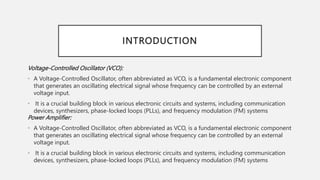
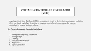
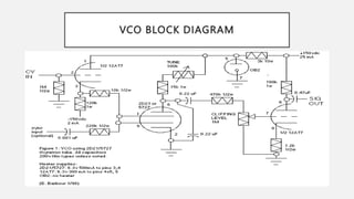
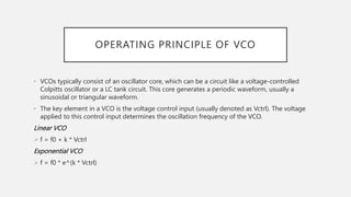
VOLTAGE-CONTROLLED OSCILLATOR
(VCO) AND POWER AMPLIFIER
By
Dr .E .Gomathi
INTRODUCTION
Voltage-Controlled Oscillator (VCO):
• A Voltage-Controlled Oscillator, often abbreviated as VCO, is a fundamental electronic component
that generates an oscillating electrical signal whose frequency can be controlled by an external
voltage input.
• It is a crucial building block in various electronic circuits and systems, including communication
devices, synthesizers, phase-locked loops (PLLs), and frequency modulation (FM) systems
Power Amplifier:
• A Voltage-Controlled Oscillator, often abbreviated as VCO, is a fundamental electronic component
that generates an oscillating electrical signal whose frequency can be controlled by an external
voltage input.
• It is a crucial building block in various electronic circuits and systems, including communication
devices, synthesizers, phase-locked loops (PLLs), and frequency modulation (FM) systems
VOLTAGE-CONTROLLED OSCILLATOR
(VCO)
• A Voltage-Controlled Oscillator (VCO) is an electronic circuit or device that generates an oscillating
electrical signal, typically a sinusoidal or a square wave, whose frequency can be precisely
controlled by varying an input voltage.
Key Feature: Frequency Controlled by Voltage:
1. Voltage-to-Frequency conversion
2. Tuning Range
3. Linearity
4. Frequency Modulation
5. Application
6. Signal Generation
VCO BLOCK DIAGRAM
OPERATING PRINCIPLE OF VCO
• VCOs typically consist of an oscillator core, which can be a circuit like a voltage-controlled
Colpitts oscillator or a LC tank circuit. This core generates a periodic waveform, usually a
sinusoidal or triangular waveform.
• The key element in a VCO is the voltage control input (usually denoted as Vctrl). The voltage
applied to this control input determines the oscillation frequency of the VCO.
Linear VCO
 f = f0 + k * Vctrl
Exponential VCO
 f = f0 * e^(k * Vctrl)
APPLICATIONS OF VCO
1. Frequency Synthesis:
2. Phase-Locked Loops (PLLs)
3. Signal Modulation
4. Frequency Agile Systems:
5. Test and Measurement
6. Frequency Tracking
7. Local Oscillators
POWER AMPLIFIER INTRODUCTION
• A power amplifier is an electronic device or circuit that is designed to increase the amplitude or
power level of an electrical signal.
• Its primary function is to take a relatively weak input signal and produce a stronger output
signal with increased power, while preserving the essential characteristics of the input signal,
such as its waveform and frequency content.
• The power amplifier begins its operation by receiving an input signal, often referred to as the
"drive" or "input" signal.
• This input signal is typically a low-power electrical signal generated by a preceding stage in an
electronic system, such as a preamplifier or a signal source
TYPES OF POWER AMPLIFIERS
1. Class A Amplifiers:
2. Class B Amplifiers
3. Class AB Amplifiers
4. Class C Amplifiers
5. Class D Amplifiers:
POWER AMPLIFIER BLOCK
DIAGRAM
EFFICIENCY AND LINEARITY
Efficiency
• Energy Conservation: In battery-powered devices and portable electronics, efficient power amplifiers
help extend battery life, ensuring longer operational periods between recharges or battery
replacements.
• Heat Dissipation: In high-power applications, inefficient amplifiers generate more heat, which can lead
to thermal issues and the need for additional cooling mechanisms. Efficient amplifiers generate less
heat, making them more reliable and cost-effective.
Linearity:
• Signal Quality: Nonlinear amplifiers can introduce harmonic distortion, intermodulation distortion,
and other unwanted artifacts, degrading the quality of the amplified signal. Linear amplifiers ensure
that the output closely matches the input.
• Interference and Compatibility: In wireless communication systems, nonlinear amplifiers can generate
spurious signals that interfere with adjacent frequency bands, violating regulatory requirements and
causing interference with other communication systems.
APPLICATIONS OF POWER AMPLIFIERS
• Audio Amplifiers
• RF (Radio Frequency) Amplifiers
• Microwave Amplifiers
• Medical Equipment
• Aerospace and Defense
• Industrial and Manufacturing
• Automotive Industry
ADVANTAGES OF VCO AND POWER
AMPLIFIER INTEGRATION
• a. Compactness: Integrating the VCO and Power Amplifier into a single module reduces the overall
footprint of the system, making it suitable for space-constrained applications.
• b. Improved Efficiency: Integration can lead to better power efficiency, as the components can be
optimized to work together seamlessly.
• c. Enhanced Performance: By fine-tuning the VCO and Power Amplifier as a unified system, engineers
can achieve better performance characteristics, such as improved signal quality and reduced signal
distortion.
• d. Cost Savings: Integrated modules can be more cost-effective than separate components, as they
reduce the need for additional connectors, cables, and interface circuits.
• e. Simplified Design: Integration simplifies the design process by providing a ready-to-use module,
reducing the complexity of designing and assembling separate VCO and Power Amplifier circuits.
CONCLUSION
• VCOs are voltage-controlled oscillators used to generate varying
frequency signals based on input voltage changes,
• while power amplifiers are circuits used to amplify the power of input
signals for various applications, with different classes offering trade-offs
between efficiency and linearity.
• Both VCOs and power amplifiers play crucial roles in electronics and
communication systems.

Voltage-Controlled Oscillator (VCO) and Power Amplifier.pptx

  • 1.
    VOLTAGE-CONTROLLED OSCILLATOR (VCO) ANDPOWER AMPLIFIER By Dr .E .Gomathi
  • 2.
    INTRODUCTION Voltage-Controlled Oscillator (VCO): •A Voltage-Controlled Oscillator, often abbreviated as VCO, is a fundamental electronic component that generates an oscillating electrical signal whose frequency can be controlled by an external voltage input. • It is a crucial building block in various electronic circuits and systems, including communication devices, synthesizers, phase-locked loops (PLLs), and frequency modulation (FM) systems Power Amplifier: • A Voltage-Controlled Oscillator, often abbreviated as VCO, is a fundamental electronic component that generates an oscillating electrical signal whose frequency can be controlled by an external voltage input. • It is a crucial building block in various electronic circuits and systems, including communication devices, synthesizers, phase-locked loops (PLLs), and frequency modulation (FM) systems
  • 3.
    VOLTAGE-CONTROLLED OSCILLATOR (VCO) • AVoltage-Controlled Oscillator (VCO) is an electronic circuit or device that generates an oscillating electrical signal, typically a sinusoidal or a square wave, whose frequency can be precisely controlled by varying an input voltage. Key Feature: Frequency Controlled by Voltage: 1. Voltage-to-Frequency conversion 2. Tuning Range 3. Linearity 4. Frequency Modulation 5. Application 6. Signal Generation
  • 4.
  • 5.
    OPERATING PRINCIPLE OFVCO • VCOs typically consist of an oscillator core, which can be a circuit like a voltage-controlled Colpitts oscillator or a LC tank circuit. This core generates a periodic waveform, usually a sinusoidal or triangular waveform. • The key element in a VCO is the voltage control input (usually denoted as Vctrl). The voltage applied to this control input determines the oscillation frequency of the VCO. Linear VCO  f = f0 + k * Vctrl Exponential VCO  f = f0 * e^(k * Vctrl)
  • 6.
    APPLICATIONS OF VCO 1.Frequency Synthesis: 2. Phase-Locked Loops (PLLs) 3. Signal Modulation 4. Frequency Agile Systems: 5. Test and Measurement 6. Frequency Tracking 7. Local Oscillators
  • 7.
    POWER AMPLIFIER INTRODUCTION •A power amplifier is an electronic device or circuit that is designed to increase the amplitude or power level of an electrical signal. • Its primary function is to take a relatively weak input signal and produce a stronger output signal with increased power, while preserving the essential characteristics of the input signal, such as its waveform and frequency content. • The power amplifier begins its operation by receiving an input signal, often referred to as the "drive" or "input" signal. • This input signal is typically a low-power electrical signal generated by a preceding stage in an electronic system, such as a preamplifier or a signal source
  • 8.
    TYPES OF POWERAMPLIFIERS 1. Class A Amplifiers: 2. Class B Amplifiers 3. Class AB Amplifiers 4. Class C Amplifiers 5. Class D Amplifiers:
  • 9.
  • 10.
    EFFICIENCY AND LINEARITY Efficiency •Energy Conservation: In battery-powered devices and portable electronics, efficient power amplifiers help extend battery life, ensuring longer operational periods between recharges or battery replacements. • Heat Dissipation: In high-power applications, inefficient amplifiers generate more heat, which can lead to thermal issues and the need for additional cooling mechanisms. Efficient amplifiers generate less heat, making them more reliable and cost-effective. Linearity: • Signal Quality: Nonlinear amplifiers can introduce harmonic distortion, intermodulation distortion, and other unwanted artifacts, degrading the quality of the amplified signal. Linear amplifiers ensure that the output closely matches the input. • Interference and Compatibility: In wireless communication systems, nonlinear amplifiers can generate spurious signals that interfere with adjacent frequency bands, violating regulatory requirements and causing interference with other communication systems.
  • 11.
    APPLICATIONS OF POWERAMPLIFIERS • Audio Amplifiers • RF (Radio Frequency) Amplifiers • Microwave Amplifiers • Medical Equipment • Aerospace and Defense • Industrial and Manufacturing • Automotive Industry
  • 12.
    ADVANTAGES OF VCOAND POWER AMPLIFIER INTEGRATION • a. Compactness: Integrating the VCO and Power Amplifier into a single module reduces the overall footprint of the system, making it suitable for space-constrained applications. • b. Improved Efficiency: Integration can lead to better power efficiency, as the components can be optimized to work together seamlessly. • c. Enhanced Performance: By fine-tuning the VCO and Power Amplifier as a unified system, engineers can achieve better performance characteristics, such as improved signal quality and reduced signal distortion. • d. Cost Savings: Integrated modules can be more cost-effective than separate components, as they reduce the need for additional connectors, cables, and interface circuits. • e. Simplified Design: Integration simplifies the design process by providing a ready-to-use module, reducing the complexity of designing and assembling separate VCO and Power Amplifier circuits.
  • 13.
    CONCLUSION • VCOs arevoltage-controlled oscillators used to generate varying frequency signals based on input voltage changes, • while power amplifiers are circuits used to amplify the power of input signals for various applications, with different classes offering trade-offs between efficiency and linearity. • Both VCOs and power amplifiers play crucial roles in electronics and communication systems.