Download to read offline
![Valmik Tilwari, Aparna Singh Kushwah / International Journal of Engineering Research and
Applications (IJERA) ISSN: 2248-9622 www.ijera.com
Vol. 3, Issue 4, Jul-Aug 2013, pp.1449-1454
1452 | P a g e
be transmitted, and those bits are divided into sub
blocks of mn bits each sub block. Those N sub blocks
will be mapped by the constellation modulator using
Gray codification, this way an + jbn values are
obtained nth constellation of the modulator. The
modulation scheme converts input data into complex
valued constellation points, according to a given
constellation, 4-QAM, 16-QAM, and 32- QAM and
so on. The Inverse Fast Fourier Transform (IFFT)
transforms the signals from the frequency domain to
the time domain. The cyclic prefix (CP) is a copy of
the last N samples from the IFFT, which are placed at
the beginning of the OFDM frame;
usually used to combat the inter-symbol interference
(ISI) and inter-channel-interference (ICI) introduced
by the multipath channel through which the signal is
propagated.
Four different duration of cyclic prefix are available
in the standard. Being G the ratio of CP time to
OFDM symbol time, this ratio can be equal to 1/32,
1/6, 1/8 and 1/4 the receiver blocks are basically the
inverse of the transmitter blocks. When
communicating over a wireless radio channel the
received signal cannot be simply modelled as a copy
of the transmitted signal corrupted by noise. At the
receiving side, a reverse process (including
deinterleaving and decoding) is executed to obtain
the original data bits. As the deinterleaving process
only changes the order of received data, the error
probability is intact. When passing through the CC
decoder and the RS-decoder, some errors may be
corrected, which results in lower error rates.
H. AWGN (Additive white Gaussian noise) Channel
The AWGN channel block adds
white Gaussian noise to real or complex input signal.
When the input signal is real, this block add real
Gaussian noise and produces a real output signal.
Additive white Gaussian noise is a channel model in
which the only impairment to communication is a
linear addition of wideband or white noise with a
constant spectral density (expressed as watts per hertz
of bandwidth) and a Gaussian distribution of
amplitude. The AWGN channel is a good model for
many satellite and deep space communication links.
If the average received power is P’[w] and the noise
power spectral density is No [W/Hz], the AWGN
channel capacity is following equation
Cawgn = W log2 (1+P’/NoW) bits/Hz
Where P’/NoW is received signal-to-noise ratio
(SNR)
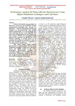
IV. SIMULATION RESULTS
The performance analysis of WiMAX 802.26e
physical layer model, simulation is performed by
considering the standard test vectors specified in the
WIMAX standard. The following subsection presents
the simulation results using the model in fig. 3, 4, 5,
6, 7, 8 and 9 for AWGN channel. BER Verses SNR.
BER is the number of error bits occurs within one
second in transmitted signal. BER define
mathematically as follow.
When the transmitter and receiver’s medium are good
in a particular time and Signal-to-Noise Ratio is high,
and then Bit Error rate is very low. In our thesis
simulation we generated random signal when noise
occurs after that we got the value of Bit error rate.
SNR= Signal Power/Noise Power
1 2 3 4 5 6 7 8
10
-5
10
-4
10
-3
10
-2
10
-1
10
0
Signal to noise ratio
Biterrorrate
Bit error rate for BPSK1/2
Fig.3. The BER results versus SNR using
BPSK
modulation schemes and ½ coding
rates
1 2 3 4 5 6 7 8
10
-5
10
-4
10
-3
10
-2
10
-1
10
0
Signal to noise ratio
Biterrorrate
Bit error rate for QPSK1/2
Fig. 4. The BER results versus SNR using
QPSK
modulation schemes and ½ coding
rates](https://image.slidesharecdn.com/hv3414491454-130729002602-phpapp01/85/Hv3414491454-4-320.jpg)
![Valmik Tilwari, Aparna Singh Kushwah / International Journal of Engineering Research and
Applications (IJERA) ISSN: 2248-9622 www.ijera.com
Vol. 3, Issue 4, Jul-Aug 2013, pp.1449-1454
1454 | P a g e
REFERENCES:-
[1] IEEE CASCOM post Graduate student
paper conference 2010 Jadavpur University,
Kolkata, India nov.27.2010; pp13-16
“Performance Analysis of WiMAX PHY”
by S.M. Lalan Chowdhury, P.
Venkateswaran.
[2] IEEE 802.16-2004, “IEEE standard for local
and Metropolitans Area Network. Part-16;
Air Interface for Fixes Broadband Wireless
Access Systems.” Rev. of IEEE 802.16-
2001, pp 1-857, Oct 2004.
[3] S. Venkatesh, K. Baskaran: “Comparative
Study of SUI Channels in IEEE802.16d
using Different Cyclic Prefix”, European
Journal of Scientific Research ISSN 1450-
216X Vol.48 No.2 (2010), pp.305-314.
[4] A. Md. Anamul Islam, C. Md. Julkarnain.
“BER performance analysis of a real data
communication through WiMAX-PHY layer
over an AWGN and Fading channel”
International journal of electrical &
computer Sciences IJECS-IJENS Vol; 10
No; 04.
[5] J.G. Andrews, A. Ghosh, R. Muhamed,
“Fundamentals of WiMAX: Understanding
Broadband Wireless Networking,” Prentice
Hall Communications AND Engineering
Technologies Series, 2007.](https://image.slidesharecdn.com/hv3414491454-130729002602-phpapp01/85/Hv3414491454-6-320.jpg)

This paper analyzes the performance of the WiMAX 802.16e physical layer utilizing various digital modulation techniques and coding rates. It highlights the advantages of WiMAX, including its high data rate and long-range capability, while presenting simulation results for bit error rates against signal-to-noise ratios. The study is implemented in MATLAB, focusing on different modulation schemes such as BPSK, QPSK, and 16-QAM to evaluate performance under additive white Gaussian noise conditions.