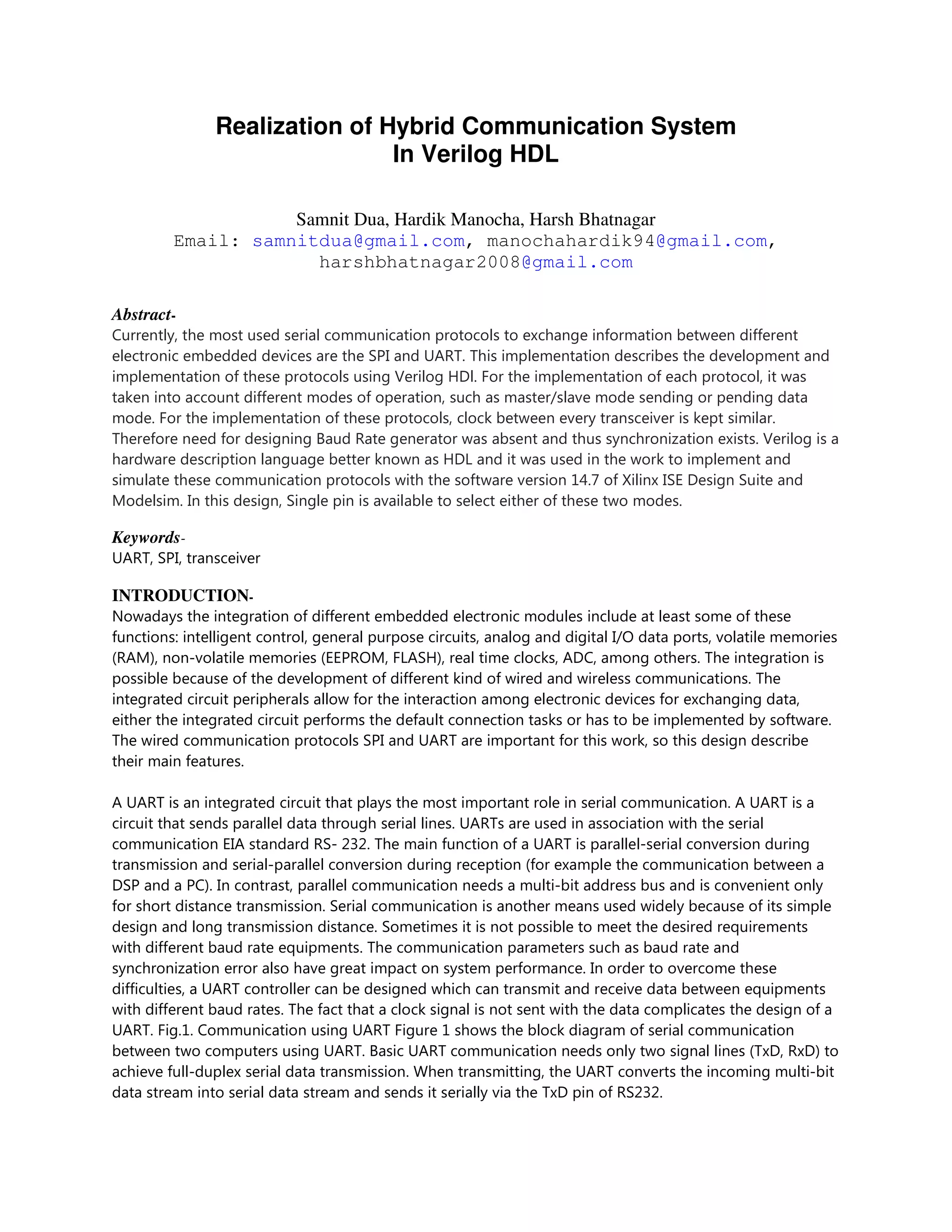
This document describes the development and implementation of the SPI and UART serial communication protocols in Verilog HDL. Both protocols were implemented considering different operating modes like master/slave and transmit/receive modes. Verilog was used to simulate the protocols in Xilinx ISE Design Suite and Modelsim. A single pin allows selecting between the SPI and UART modes.
Realization of Hybrid Communication System in Verilog HDL
1. Realization of Hybrid Communication System
In Verilog HDL
Samnit Dua, Hardik Manocha, Harsh Bhatnagar
Email: samnitdua@gmail.com, manochahardik94@gmail.com,
harshbhatnagar2008@gmail.com
Abstract-
Currently, the most used serial communication protocols to exchange information between different
electronic embedded devices are the SPI and UART. This implementation describes the development and
implementation of these protocols using Verilog HDl. For the implementation of each protocol, it was
taken into account different modes of operation, such as master/slave mode sending or pending data
mode. For the implementation of these protocols, clock between every transceiver is kept similar.
Therefore need for designing Baud Rate generator was absent and thus synchronization exists. Verilog is a
hardware description language better known as HDL and it was used in the work to implement and
simulate these communication protocols with the software version 14.7 of Xilinx ISE Design Suite and
Modelsim. In this design, Single pin is available to select either of these two modes.
Keywords-
UART, SPI, transceiver
INTRODUCTION-
Nowadays the integration of different embedded electronic modules include at least some of these
functions: intelligent control, general purpose circuits, analog and digital I/O data ports, volatile memories
(RAM), non-volatile memories (EEPROM, FLASH), real time clocks, ADC, among others. The integration is
possible because of the development of different kind of wired and wireless communications. The
integrated circuit peripherals allow for the interaction among electronic devices for exchanging data,
either the integrated circuit performs the default connection tasks or has to be implemented by software.
The wired communication protocols SPI and UART are important for this work, so this design describe
their main features.
A UART is an integrated circuit that plays the most important role in serial communication. A UART is a
circuit that sends parallel data through serial lines. UARTs are used in association with the serial
communication EIA standard RS- 232. The main function of a UART is parallel-serial conversion during
transmission and serial-parallel conversion during reception (for example the communication between a
DSP and a PC). In contrast, parallel communication needs a multi-bit address bus and is convenient only
for short distance transmission. Serial communication is another means used widely because of its simple
design and long transmission distance. Sometimes it is not possible to meet the desired requirements
with different baud rate equipments. The communication parameters such as baud rate and
synchronization error also have great impact on system performance. In order to overcome these
difficulties, a UART controller can be designed which can transmit and receive data between equipments
with different baud rates. The fact that a clock signal is not sent with the data complicates the design of a
UART. Fig.1. Communication using UART Figure 1 shows the block diagram of serial communication
between two computers using UART. Basic UART communication needs only two signal lines (TxD, RxD) to
achieve full-duplex serial data transmission. When transmitting, the UART converts the incoming multi-bit
data stream into serial data stream and sends it serially via the TxD pin of RS232.
2. SPI (Serial Protocol Interface). The SPI bus is a 4-wire full-duplex interface synchronous serial data link.
Indeed, it is a (3+N)-wire interface where N is the number of devices connected to a single master device
on the bus. Only one master can be active on the bus. Like UART, SPI supports a transfer size of integer
multiples of 8 bits. Technically the SPI bus shift register’s length limits the size of the data transfers. The
SPI bus can support a variety of transfer speeds but the bus is limited by the system´s clock. The SPI
interface is generally is able data rates of several Mbits/sec. This design describes the procedure used to
implement the synchronous serial communication protocols SPI and UART by means of the hardware
programming language Verilog HDL (Hardware Description Language).
WAVEFORMS:
4. TIMING ANALYSIS:
Speed Grade: -5
Minimum period: 5.250ns (Maximum Frequency: 190.480MHz)
Minimum input arrival time before clock: 130.882ns
Maximum output required time after clock: 6.141ns
Maximum combinational path delay: No path found
====================================================================
Process "Synthesize - XST" completed successfully
FUTURE SCOPE
Resides in using this communication protocol design for implementing T-DES, where DES would be
replaced by Hybrid AES-DES. Implementation of such design would increase the difficulties in cracking the
algorithm; thereby further increasing security far from simple AES. T-hybrid AES-DES would employ this
design in SPI mode.
CONCLUSION
In this project, we have implemented a mix of two different communication protocols under a single chip
design. Protocols developed are UART and SPI. In UART, one transceiver transmits the data to another
transceiver. For UART mode, Select =1. While Select=0, for SPI mode, where second transceiver transmits
data to third and finally third transceiver passes back to first. Validation of design is shown under
Waveforms.
ACKNOWLEDGMENT
We would like to especially thank our project guide Mr. Harsh Bhatnagar whose valuable suggestions
helped shape the basis of our project idea.
REFRENCES
[1] www.opencore.org.Simon Srot. SPI Master Core Specification,Rev.0.6. May 16,2007
[2] Prophet, Graham. Communications IP adds SPI interface to FP-GA. EDN, v 48, n 27, Dec 11, 2003.
[3] Motorola, "MC68HC II manual,".
[4] Smart Computing Dictionary, Serial Peripheral Interface (SPI)
(online)http://www.smartcomputing.com/editorial/dictiona ry/detai l.asp?guid=&searchtype=
1&DicID=12820&RefType=Dictionary (access date 28May 2006)
[5] Frédéric Leens , An Introduction to I2C and SPI Protocols,IEEE Xplore.
5. [6] ZHANG Yan-wei, Verilog HDL detailed design procedure, Posts & Telecom Press
[7] Mohd Yamani Idna Idris, Mashkuri Yaacob, Zaidi Razak, “A VHDL Implementation of UART Design with
BIST capability”
[8] Dr. T.V.S.P. Gupta, Y. Kumari, M.Asok Kumar”UART realization with BIST architecture using VHDL”
International Journal of Engineering Research and Applications(IJERA) ISSN: 2248-9622 www.ijera.com Vol.
3, Issue 1, January -February 2013, pp.636-640
[9] M.S. Harvey,Generic UART Manual,Silicon Valley,December 1999.