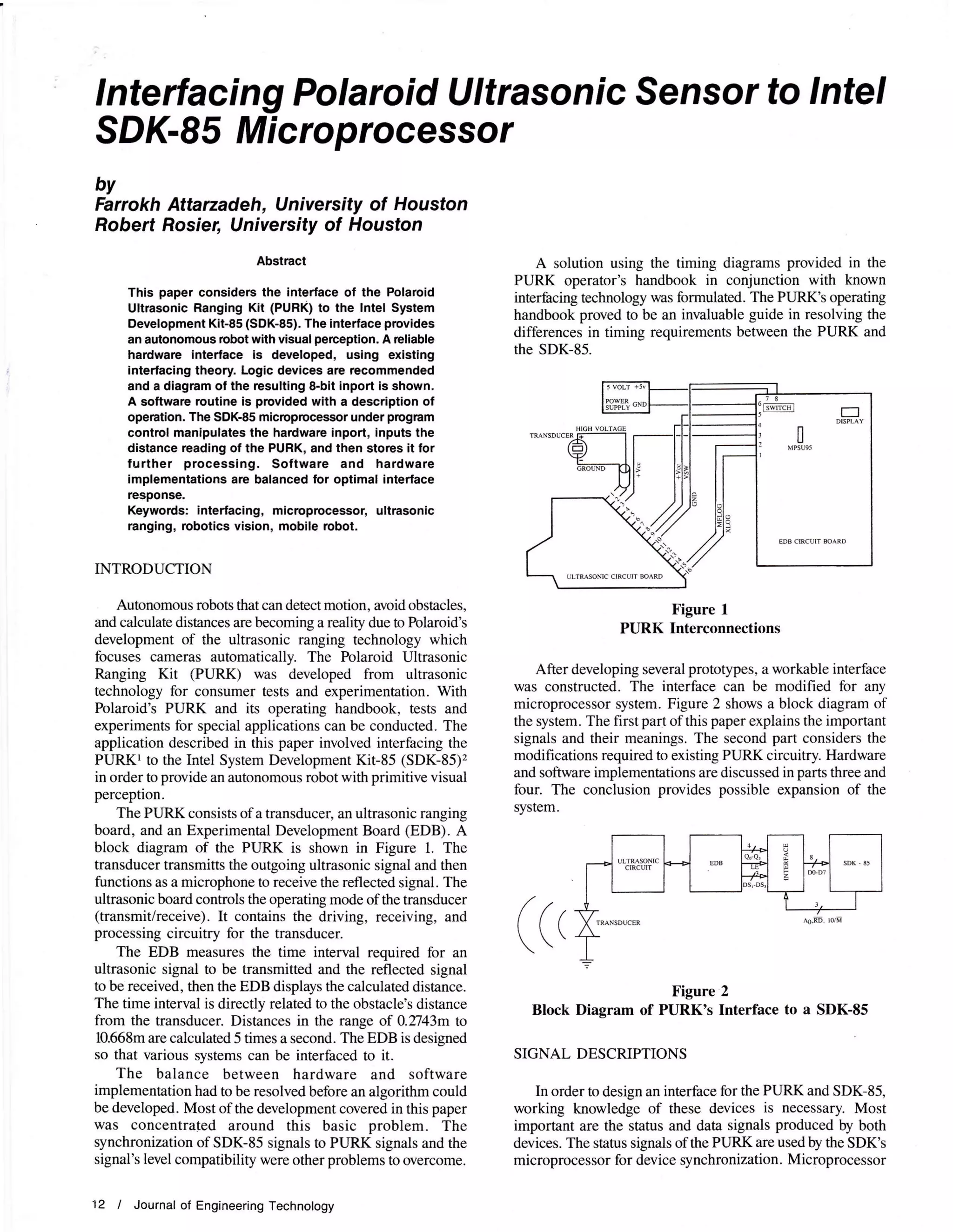
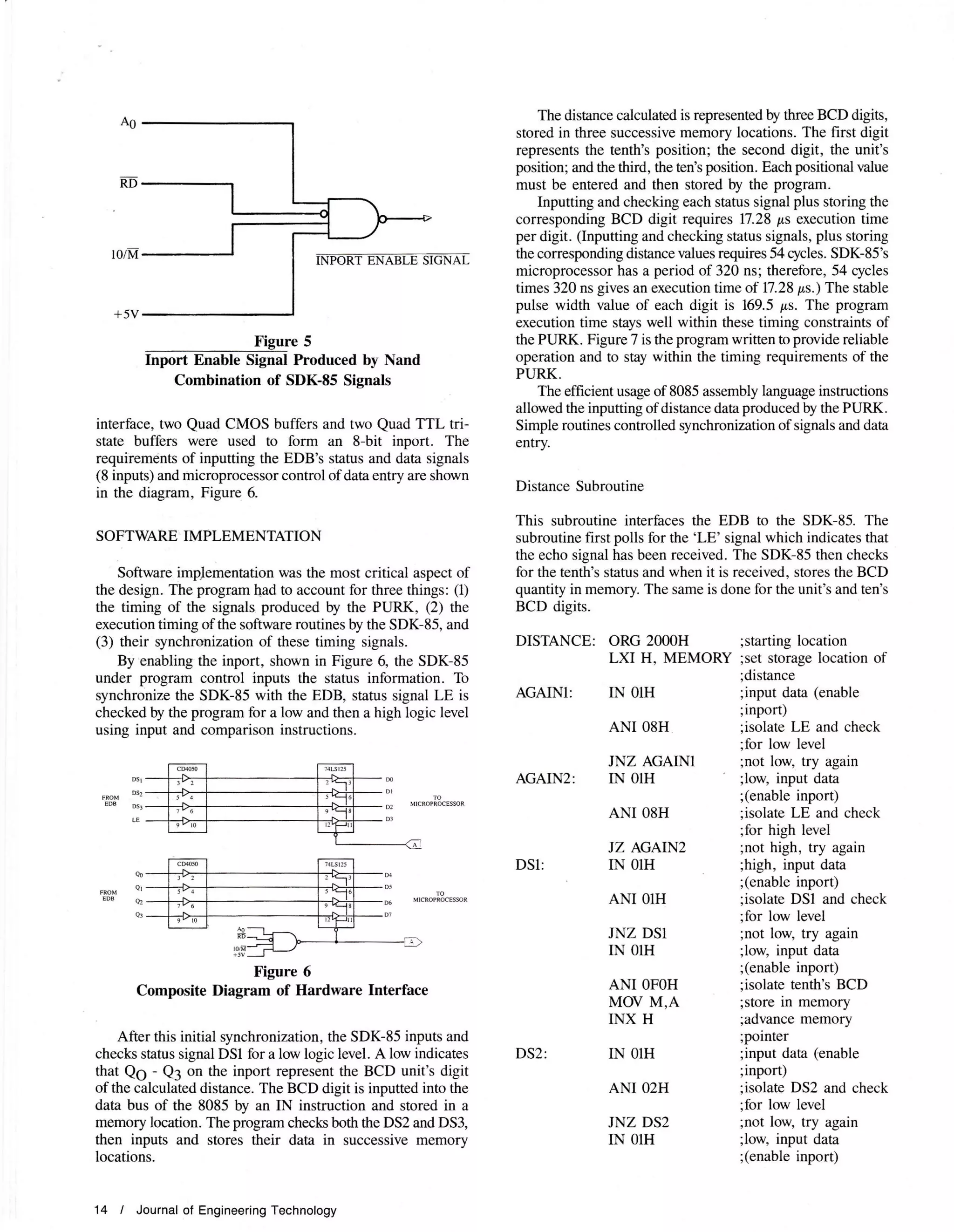
lnterfacing Polaroid Ultrasonic Sensor to lntel
SDK-85 Microprocessor
by
Farrokh Attarzadeh, University of Houston
Robert Rosier, University of Houston
Abstract
This paper considers the interface of the Polaroid
Ultrasonic Ranging Kit (PURK) to the lntel System
Development Kit-85 (SDK-85). The interlace provides
an autonomous robot with visual perception, A rcliable
haldware interface is developed, using existing
interracing theory. Logic devices are recommended
and a diagram ol the resulting 8-bit inport is shown.
A software routine is provided wlth a description of
operation. The SOK-85 microprocessor under program
control manipulates the hardware inport, inputs the
distance reading of the PURK, and then stores it lor
further processing. Software and hardware
implementations are balanced for optimal interface
response.
Keywords: interfacing, microprocessor, ultrasonic
ranging, robotics vision, mobile tobot.
INTRODUCTION
Autonomous robots that can detect motion, avoid obstacles,
and calculate distances are becoming a reality due to Polaroid's
development of the ultrasonic ranging technology which
focuses cameras automatically. The Polaroid Ultrasonic
Ranging Kit (PURK) was developed from ultrasonic
technology for consumer tests and experimentation. With
Polaroid's PURK and is operating handbook, tests and
experiments for special applications can be conducted. The
application described in this paper involved interfacing the
PURKT to the Intel System Development Kit-85 (SDK-85)'z
in order to provide an autonomous robot with primitive visual
perception.
The PURK consists of a transducer, an ultrasonic ranging
board, and an Experimental Development Board (EDB). A
block diagram of the PURK is shown in Figure L The
transducer transmitts the outgoing ultrasonic signal and then
functions as a microphone to receive the reflected signal. The
ultrasonic board controls the operating mode of the transducer
(transmit/receive). It contains the driving, receiving, and
processing circuitry for the transducer.
The EDB measures the time interval required for an
ultrasonic signal to be transmitted and the reflected signal
to be received, then the EDB displays the calculated distance.
The time interval is directly related to the obstacle's distance
from the transducer. Distances in the range of 0.2743m to
10.668m are calculated 5 times a second. The EDB is designed
so that various systems can be interfaced to it.
The balance between hardware and software
implementation had to be resolved before an algorithm could
be developed. Most of the development covered in this paper
was concentrated around this basic problem. The
synchronization of SDK-85 signals to PURK signals and the
signal's level compatibility were other problems to overcome.
12 I Journal of Engineering Technology
A solution using the timing diagrams provided in the
PURK operator's handbook in conjunction with known
interhcing technology was formulated. The PURK's operating
handbook proved to be an invaluable guide in resolving the
differences in timing requirements between the PURK and
the SDK-85.
Figure 1
PURK Interconnections
After developing several prototypes, a workable interface
was constructed. The interface can be modified for any
microprocessor system. Figure 2 shows a block diagram of
the system. The first part of this paper explains the important
signals and their meanings, The second part considers the
modifications required to existing PURK circuitry. Hardware
and software implementations are discussed in parts three and
four. The conclusion provides possible expansion of the
system.
Figure 2
Block Diagram of PURK's Interface to a SDK-85
SIGNAL DESCRIPTIONS
In order to design an interface for the PURK and SDK-85,
working knowledge of these devices is necessary. Most
important are the status and data signals produced by both
devices. The status signals of the PURK are used by the SDK's
microprocessor for device synchronization. Microprocessor
EDB CIRCUIT BOARD
ULTRASONIC CIRCUT MARD
(c,
control signals are combined to input the distance data
produced by the EDB. Figure 2 indicates the signal flow.
LE:
LE is an EDB-generated signal. A low to high transition
indicates that the reflected signal has been detected and the
distance calculated. The microprocessor checks for this
condition to synchronize itself to the EDB. When this initial
transition takes place, the distance data is inputted and stored
in the SDK's memory.
Qe - Q3:
These four signals represent the BCD value of the
calculated distance. They are transferred from the EDB to
the SDK-85 by the microprocessor's IN instruction. The
distance is represented with three significant BCD figures
which are the tenth's, unit's, and ten's position. Each BCD
digit is multiplexed on the input of the inport at regular
intervals.
DSI:
DSl is an EDB-generated signal whose active low
condition indicates that the corresponding data (Qg - Q3)
is the tenth's BCD value of distance. the microprocessor checks
for this low condition.
DS2:
DS2 is the same as DSl, except it indicates the unit's BCD
value of distance is on the QO - Ql lines.
DS3:
DS3 is the same as DSl, except it indicates the ten's BCD
value of distance is on the Qg - Q3 lines.
IO/M, RD AO
These signals are produced by the SDK-85's
microprocessor. Combination of these signals produces an
enable signal to control data transfer.
SYSTEM MODIFICATION
Only one modiflcation to the existing PURK system was
necessary but successful interface operation depended on it.
The modification to the EDB required pin 4 of MC145533
to be disconnected from pin 9 of MC140403 and connected
to pin 4 of MC14O[0. This modification expands the pulse
width of DSl, DS2, and DS3 from 4.8 ps to 169,5 ps. This
also increases the valid distance width (Qg - Q:) to 169.5 ps.
The software routine requires 17.28 ps to input a status
signal (DSl, DS2, DS3), verifu it, input the distance data,
and store the data in memory. The modification provided the
software routine with a sufficient time span to perform its
stated function. Figure 3 shows timing diagrams for DS1, DS2,
DS3, and QO - Q:.
**
Figure 3
Timing Diagram of DS and Q Signals
HARDWARE INTEREACE
The hardware interfuce had to deal with two basic factors.
These were: (1) the interface of CMOS logic levels of the EDB
to TTL logic levels of the SDK-85 in a 5-volt system and (2)
microprocessor control of status and data entry.
CMOS to TTL interface required the translation of CMOS
logic levels to TTL logic levels with the CMOS device required
to handle the higher currents of TTLJ Several CMOS devices
exist that can accomplish the logic translation and handle the
current requirements. The CD4049UB, CD405OB, and
CD404IB were chosen because they can drive two TTL gates
in a 5-volt system. Figure 4 shows the connection of a CMOS
output to a TTL input in a 5-volt system.
Figure 4
CMOS to TTL Interface
Status and data entry from the EDB must be controlled
so that the microprocessor can access it when needed for
processing. A 74L5125 tri-state buffer accomplishes this
function.s The 74L5725 is connected to form a 4-bit inport
to the SDK-85. A TTL NAND gate combines microprocessor
control signals. The:gr.rblatiqqptglq.oprocessor control
signals produces an Inport Enable Signal which activates the
inport. This allows the entry of data from the EDB to the
SDK-85. Figure 5 shows this interface
Many different IC configurations of CMOS
buffers/inverters, TTL tri-state buffers, and TTL NAND gates
could have been utilized. The selection depends on the
applicatons and parts availability. One octal CMOS buffer
driving one octal TTL trlstate buffer is the most efficient
configuration for the SDK-85's 8-bit processor. For this
Spring 1987 I 13
t0/M
+5V
Inport Enable Signal Produced by Nand
Combination of SDK-85 Signals
interface, two Quad CMOS buffers and two Quad TTL tri-
state buffers were used to form an 8-bit inport. The
requirements of inputting the EDB's status and data signals
(8 inputs) and microprocessor control of data entry are shown
in the diagram, Figure 6.
SOFTWARE IMPLEMENTATION
Software impJementation was the most critical aspect of
the design. The program had to account for three things; (1)
the timing of the signals produced by the PURK, (2) the
executiontiming of the software routines by the SDK-85, and
(3) their synchronization of these timing signals.
By enabling the inport, shown in Figure 6, the SDK-85
under program control inputs the status information. To
synchronize the SDK-85 with the EDB, status signal LE is
checked by the program for a low and then a high logic level
using input and comparison instructions.
DSI:
Figure 6
Composite Diagram of Hardware Interface
After this initial synchronization, the SDK-85 inputs and
checks status signal DSl for a low logic level. A low indicates DS2:
that Q6 - Q3 on the inport represent the BCD unit's digit
of the calculated distance. The BCD digit is inputted into the
data bus of the 8085 by an IN instruction and stored in a
memory location. Theprogram check both the DS2 and DS3,
then inputs and stores their data in successive memory
locations.
14 / Journal of Engineering Technology
The distance calculated is represented by three BCD digits,
stored in three successive memory locations. The first digit
represents the tenth's position; the second digit, the unit's
position; and the third, the ten's position. Each positional value
must be entered and then stored by the program.
Inputting and checking each status signal plus storing the
corresponding BCD digit requires 17.28 ps execution time
per digit. (Inputting and checking status signals, plus storing
the corresponding disance values requires 54 cycles. SDK-85's
microprocessor has a period of 320 ns; therefore, 54 cycles
times 320 ns gives an execution time of 17.28 p,s.) The stable
pulse width value of each digit is 169.5 ps. The program
execution time stays well within these timing constraints of
the PURK. Figure 7 is the program written to provide reliable
operation and to stay within the timing requirements of the
PURK.
The efficient usage of 8085 assembly language instructions
allowed the inputting of distance data produced by the PURK.
Simple routines controlled synchronization of signals and data
entry.
Distance Subroutine
This subroutine interfaces the EDB to the SDK-85. The
subroutine first polls for the 'LE' signal which indicates that
the echo signal has been received. The SDK-85 then checks
for the tenth's status and when it is received, stores the BCD
quantity in memory. The same is done for the unit's and ten's
BCD digits.
DISTANCE: ORG 2000H ;starting location
LXI H, MEMORY ;set storage location of
;distance
AGAINI: IN OlH ;input data (enable
;inport)
ANI 08H ;isolate LE and check
;for low level
JNZ AGAIN1 ;not low, try again
AGAIN2: IN OlH ;low, input data
;(enable inport)
;isolate LE and check
;for high level
;not high, try again
;high, input daa
;(enable inport)
;isolate DSI and check
;for low level
;not low, try again
;low, input data
;(enable inport)
;isolate tenth's BCD
;store in memory
;advance memory
;pointer
;input data (enable
;inport)
;isolate DS2 and check
;for low level
;not low, try again
;low, input data
;(enable inport)
Dst
DS,
EDB DS3
LE
ANI O8H
JZ AGAIN2
IN OIH
ANI OlH
JNZ DS1
TN OIH
ANI OFOH
MOV M,A
INX H
IN OlH
ANI O2H
JNZ DS2
IN OlH
DS3:
AM O4H
JNZ DS3
IN OlH
ANI OFOH
MOV M,A
MEMORY DS O3H
RET ;return to the calling
;program
Figure 7
Assembly Program for Software Implementation
CONCLUSION
In this paper, the Folaroid lJltrasonic Ranging Kit (PURK)
was interfaced to the System Development Kit-85 (SDK-85)
using existing interface theory and 8085 instructions. This
enables an autonomous mobile robot to sense motion, detect
objects, and calculate distances. With modifications, any
microprocessor system can use the resultant interface.
Future modifications of the PURK will allow
microprocessor control of ranging functions to multiple
transducers. This would provide a mobile robot with increased
perception, but would require a more complex hardware and
software scheme.
A demultiplexer whose output is microprocessor-
controlled can be used to enable switching relays. The relays
can in turn gate the generated ultrasonic signal to one of a
number of transducers. Relays are recommended for the
switching medium, because 300 volts are applied to the
transducer during signal transmission. Relays which can
handle this voltage across their contacts are readily available.
The most important advantage is the lower cost of a relay
for each transducer, compared to the cost of a PURK for each
transducer.
Software modification for future expansion requires that
a program (l) select one of the multiple transducers by
providing a select code to a decoder and (2) initiate ranging
functions with a subroutine-generated switching signal. This
switching signal initiates ranging action. Both tasks can be
performed with the standard 8085 instruction set.
REFERENCES
l. Uhrasonic Ranging System Manual arud ,Mdendum,
Polaroid Corporation, Cambridge, Massachusetts, 1980.
2. SDK-85 System Design Kit User's Manual, Intel
Corporation, Santa Clara, California, 1978.
3. Motorola CMOS Databook, Motorola Corporation,
Austin, Texas, 1978.
4. Lancaster, Don, CMOS Cookbook, Howard W. Sams &
Company, Indianapolis, 1984.
5. Lancaster, Don, TTL Cookbook, Howard W. Sams &
Compahy, Indianapolis, 1982.
Farrokh Attarzadeh is an Assistant Protessor of Electrical and
Electronics Technology at the University of Houston, Houston,
Texas. He holds a B.S.E.E. (1970) from California State Polytechnic
University; an M.S.E.E. (1972) from California State Univercity, tong
Beach; and a Ph.D. (1983) in Electrical Engineering from the
Univercity of Houston. Prior to entering the teaching prcfession,
he was with Brown & Root, lnc., and Fluor Engineel€, lnc., both
engineering and construction companies in Houston. He taught
computer programming languages atthe College of Technology,
University of Houston, for over five yearc on a part-time basis
betorc ioining the laculty of the Electrical-Electr6nics Department
on a full-time basis in 1983. At prcsent he is teaching compuiel
hardware and software coursies and ass.embly language
programming, and actively doing rcsearch in the field ol robotics.
He has established a robotics research laboratory in the College
and directs and supervises several upper-division students in
various phases ol the ongoing robotics-related proiects. He is
a Registered Professiona! Engineer in the State of Texas and a
member of ASEE, SME, Rl, and lSA.
Robert Rosier is a senior in Electrical and Electronics Engineering
Technology at the Unaversity of Houston. His work experience
includes five years as a field service engineer with 3M Corporation
and Texas American Microfilm. He is currently working as a
teaching assistant in the ELET Department. He studied digital
electronics at Elkins lnstitute and Devry lnstitute ol Technology
belore coming to the University of Houston. Mr. Rosier has been
on the Dean's List since ioining the University ol Houston, and
he is a member of Tau Alpha Phi Honor Society.
ANI OFOH
MOV M,A
INX H
IN OlH
;isolate unit's BCD
;store in memory
;advance memory
;pointer
;input data (enable
;inport)
;isolate DS3 and check
;for low level
;not low, try again
;low, input data
;(enable inport)
;isolate ten's BCD
;store in memory
;allocate three memory
:locations
Spring 1987 / 15

Robotic Project - published paper

  • 1.
    lnterfacing Polaroid UltrasonicSensor to lntel SDK-85 Microprocessor by Farrokh Attarzadeh, University of Houston Robert Rosier, University of Houston Abstract This paper considers the interface of the Polaroid Ultrasonic Ranging Kit (PURK) to the lntel System Development Kit-85 (SDK-85). The interlace provides an autonomous robot with visual perception, A rcliable haldware interface is developed, using existing interracing theory. Logic devices are recommended and a diagram ol the resulting 8-bit inport is shown. A software routine is provided wlth a description of operation. The SOK-85 microprocessor under program control manipulates the hardware inport, inputs the distance reading of the PURK, and then stores it lor further processing. Software and hardware implementations are balanced for optimal interface response. Keywords: interfacing, microprocessor, ultrasonic ranging, robotics vision, mobile tobot. INTRODUCTION Autonomous robots that can detect motion, avoid obstacles, and calculate distances are becoming a reality due to Polaroid's development of the ultrasonic ranging technology which focuses cameras automatically. The Polaroid Ultrasonic Ranging Kit (PURK) was developed from ultrasonic technology for consumer tests and experimentation. With Polaroid's PURK and is operating handbook, tests and experiments for special applications can be conducted. The application described in this paper involved interfacing the PURKT to the Intel System Development Kit-85 (SDK-85)'z in order to provide an autonomous robot with primitive visual perception. The PURK consists of a transducer, an ultrasonic ranging board, and an Experimental Development Board (EDB). A block diagram of the PURK is shown in Figure L The transducer transmitts the outgoing ultrasonic signal and then functions as a microphone to receive the reflected signal. The ultrasonic board controls the operating mode of the transducer (transmit/receive). It contains the driving, receiving, and processing circuitry for the transducer. The EDB measures the time interval required for an ultrasonic signal to be transmitted and the reflected signal to be received, then the EDB displays the calculated distance. The time interval is directly related to the obstacle's distance from the transducer. Distances in the range of 0.2743m to 10.668m are calculated 5 times a second. The EDB is designed so that various systems can be interfaced to it. The balance between hardware and software implementation had to be resolved before an algorithm could be developed. Most of the development covered in this paper was concentrated around this basic problem. The synchronization of SDK-85 signals to PURK signals and the signal's level compatibility were other problems to overcome. 12 I Journal of Engineering Technology A solution using the timing diagrams provided in the PURK operator's handbook in conjunction with known interhcing technology was formulated. The PURK's operating handbook proved to be an invaluable guide in resolving the differences in timing requirements between the PURK and the SDK-85. Figure 1 PURK Interconnections After developing several prototypes, a workable interface was constructed. The interface can be modified for any microprocessor system. Figure 2 shows a block diagram of the system. The first part of this paper explains the important signals and their meanings, The second part considers the modifications required to existing PURK circuitry. Hardware and software implementations are discussed in parts three and four. The conclusion provides possible expansion of the system. Figure 2 Block Diagram of PURK's Interface to a SDK-85 SIGNAL DESCRIPTIONS In order to design an interface for the PURK and SDK-85, working knowledge of these devices is necessary. Most important are the status and data signals produced by both devices. The status signals of the PURK are used by the SDK's microprocessor for device synchronization. Microprocessor EDB CIRCUIT BOARD ULTRASONIC CIRCUT MARD (c,
  • 2.
    control signals arecombined to input the distance data produced by the EDB. Figure 2 indicates the signal flow. LE: LE is an EDB-generated signal. A low to high transition indicates that the reflected signal has been detected and the distance calculated. The microprocessor checks for this condition to synchronize itself to the EDB. When this initial transition takes place, the distance data is inputted and stored in the SDK's memory. Qe - Q3: These four signals represent the BCD value of the calculated distance. They are transferred from the EDB to the SDK-85 by the microprocessor's IN instruction. The distance is represented with three significant BCD figures which are the tenth's, unit's, and ten's position. Each BCD digit is multiplexed on the input of the inport at regular intervals. DSI: DSl is an EDB-generated signal whose active low condition indicates that the corresponding data (Qg - Q3) is the tenth's BCD value of distance. the microprocessor checks for this low condition. DS2: DS2 is the same as DSl, except it indicates the unit's BCD value of distance is on the QO - Ql lines. DS3: DS3 is the same as DSl, except it indicates the ten's BCD value of distance is on the Qg - Q3 lines. IO/M, RD AO These signals are produced by the SDK-85's microprocessor. Combination of these signals produces an enable signal to control data transfer. SYSTEM MODIFICATION Only one modiflcation to the existing PURK system was necessary but successful interface operation depended on it. The modification to the EDB required pin 4 of MC145533 to be disconnected from pin 9 of MC140403 and connected to pin 4 of MC14O[0. This modification expands the pulse width of DSl, DS2, and DS3 from 4.8 ps to 169,5 ps. This also increases the valid distance width (Qg - Q:) to 169.5 ps. The software routine requires 17.28 ps to input a status signal (DSl, DS2, DS3), verifu it, input the distance data, and store the data in memory. The modification provided the software routine with a sufficient time span to perform its stated function. Figure 3 shows timing diagrams for DS1, DS2, DS3, and QO - Q:. ** Figure 3 Timing Diagram of DS and Q Signals HARDWARE INTEREACE The hardware interfuce had to deal with two basic factors. These were: (1) the interface of CMOS logic levels of the EDB to TTL logic levels of the SDK-85 in a 5-volt system and (2) microprocessor control of status and data entry. CMOS to TTL interface required the translation of CMOS logic levels to TTL logic levels with the CMOS device required to handle the higher currents of TTLJ Several CMOS devices exist that can accomplish the logic translation and handle the current requirements. The CD4049UB, CD405OB, and CD404IB were chosen because they can drive two TTL gates in a 5-volt system. Figure 4 shows the connection of a CMOS output to a TTL input in a 5-volt system. Figure 4 CMOS to TTL Interface Status and data entry from the EDB must be controlled so that the microprocessor can access it when needed for processing. A 74L5125 tri-state buffer accomplishes this function.s The 74L5725 is connected to form a 4-bit inport to the SDK-85. A TTL NAND gate combines microprocessor control signals. The:gr.rblatiqqptglq.oprocessor control signals produces an Inport Enable Signal which activates the inport. This allows the entry of data from the EDB to the SDK-85. Figure 5 shows this interface Many different IC configurations of CMOS buffers/inverters, TTL tri-state buffers, and TTL NAND gates could have been utilized. The selection depends on the applicatons and parts availability. One octal CMOS buffer driving one octal TTL trlstate buffer is the most efficient configuration for the SDK-85's 8-bit processor. For this Spring 1987 I 13
  • 3.
    t0/M +5V Inport Enable SignalProduced by Nand Combination of SDK-85 Signals interface, two Quad CMOS buffers and two Quad TTL tri- state buffers were used to form an 8-bit inport. The requirements of inputting the EDB's status and data signals (8 inputs) and microprocessor control of data entry are shown in the diagram, Figure 6. SOFTWARE IMPLEMENTATION Software impJementation was the most critical aspect of the design. The program had to account for three things; (1) the timing of the signals produced by the PURK, (2) the executiontiming of the software routines by the SDK-85, and (3) their synchronization of these timing signals. By enabling the inport, shown in Figure 6, the SDK-85 under program control inputs the status information. To synchronize the SDK-85 with the EDB, status signal LE is checked by the program for a low and then a high logic level using input and comparison instructions. DSI: Figure 6 Composite Diagram of Hardware Interface After this initial synchronization, the SDK-85 inputs and checks status signal DSl for a low logic level. A low indicates DS2: that Q6 - Q3 on the inport represent the BCD unit's digit of the calculated distance. The BCD digit is inputted into the data bus of the 8085 by an IN instruction and stored in a memory location. Theprogram check both the DS2 and DS3, then inputs and stores their data in successive memory locations. 14 / Journal of Engineering Technology The distance calculated is represented by three BCD digits, stored in three successive memory locations. The first digit represents the tenth's position; the second digit, the unit's position; and the third, the ten's position. Each positional value must be entered and then stored by the program. Inputting and checking each status signal plus storing the corresponding BCD digit requires 17.28 ps execution time per digit. (Inputting and checking status signals, plus storing the corresponding disance values requires 54 cycles. SDK-85's microprocessor has a period of 320 ns; therefore, 54 cycles times 320 ns gives an execution time of 17.28 p,s.) The stable pulse width value of each digit is 169.5 ps. The program execution time stays well within these timing constraints of the PURK. Figure 7 is the program written to provide reliable operation and to stay within the timing requirements of the PURK. The efficient usage of 8085 assembly language instructions allowed the inputting of distance data produced by the PURK. Simple routines controlled synchronization of signals and data entry. Distance Subroutine This subroutine interfaces the EDB to the SDK-85. The subroutine first polls for the 'LE' signal which indicates that the echo signal has been received. The SDK-85 then checks for the tenth's status and when it is received, stores the BCD quantity in memory. The same is done for the unit's and ten's BCD digits. DISTANCE: ORG 2000H ;starting location LXI H, MEMORY ;set storage location of ;distance AGAINI: IN OlH ;input data (enable ;inport) ANI 08H ;isolate LE and check ;for low level JNZ AGAIN1 ;not low, try again AGAIN2: IN OlH ;low, input data ;(enable inport) ;isolate LE and check ;for high level ;not high, try again ;high, input daa ;(enable inport) ;isolate DSI and check ;for low level ;not low, try again ;low, input data ;(enable inport) ;isolate tenth's BCD ;store in memory ;advance memory ;pointer ;input data (enable ;inport) ;isolate DS2 and check ;for low level ;not low, try again ;low, input data ;(enable inport) Dst DS, EDB DS3 LE ANI O8H JZ AGAIN2 IN OIH ANI OlH JNZ DS1 TN OIH ANI OFOH MOV M,A INX H IN OlH ANI O2H JNZ DS2 IN OlH
  • 4.
    DS3: AM O4H JNZ DS3 INOlH ANI OFOH MOV M,A MEMORY DS O3H RET ;return to the calling ;program Figure 7 Assembly Program for Software Implementation CONCLUSION In this paper, the Folaroid lJltrasonic Ranging Kit (PURK) was interfaced to the System Development Kit-85 (SDK-85) using existing interface theory and 8085 instructions. This enables an autonomous mobile robot to sense motion, detect objects, and calculate distances. With modifications, any microprocessor system can use the resultant interface. Future modifications of the PURK will allow microprocessor control of ranging functions to multiple transducers. This would provide a mobile robot with increased perception, but would require a more complex hardware and software scheme. A demultiplexer whose output is microprocessor- controlled can be used to enable switching relays. The relays can in turn gate the generated ultrasonic signal to one of a number of transducers. Relays are recommended for the switching medium, because 300 volts are applied to the transducer during signal transmission. Relays which can handle this voltage across their contacts are readily available. The most important advantage is the lower cost of a relay for each transducer, compared to the cost of a PURK for each transducer. Software modification for future expansion requires that a program (l) select one of the multiple transducers by providing a select code to a decoder and (2) initiate ranging functions with a subroutine-generated switching signal. This switching signal initiates ranging action. Both tasks can be performed with the standard 8085 instruction set. REFERENCES l. Uhrasonic Ranging System Manual arud ,Mdendum, Polaroid Corporation, Cambridge, Massachusetts, 1980. 2. SDK-85 System Design Kit User's Manual, Intel Corporation, Santa Clara, California, 1978. 3. Motorola CMOS Databook, Motorola Corporation, Austin, Texas, 1978. 4. Lancaster, Don, CMOS Cookbook, Howard W. Sams & Company, Indianapolis, 1984. 5. Lancaster, Don, TTL Cookbook, Howard W. Sams & Compahy, Indianapolis, 1982. Farrokh Attarzadeh is an Assistant Protessor of Electrical and Electronics Technology at the University of Houston, Houston, Texas. He holds a B.S.E.E. (1970) from California State Polytechnic University; an M.S.E.E. (1972) from California State Univercity, tong Beach; and a Ph.D. (1983) in Electrical Engineering from the Univercity of Houston. Prior to entering the teaching prcfession, he was with Brown & Root, lnc., and Fluor Engineel€, lnc., both engineering and construction companies in Houston. He taught computer programming languages atthe College of Technology, University of Houston, for over five yearc on a part-time basis betorc ioining the laculty of the Electrical-Electr6nics Department on a full-time basis in 1983. At prcsent he is teaching compuiel hardware and software coursies and ass.embly language programming, and actively doing rcsearch in the field ol robotics. He has established a robotics research laboratory in the College and directs and supervises several upper-division students in various phases ol the ongoing robotics-related proiects. He is a Registered Professiona! Engineer in the State of Texas and a member of ASEE, SME, Rl, and lSA. Robert Rosier is a senior in Electrical and Electronics Engineering Technology at the Unaversity of Houston. His work experience includes five years as a field service engineer with 3M Corporation and Texas American Microfilm. He is currently working as a teaching assistant in the ELET Department. He studied digital electronics at Elkins lnstitute and Devry lnstitute ol Technology belore coming to the University of Houston. Mr. Rosier has been on the Dean's List since ioining the University ol Houston, and he is a member of Tau Alpha Phi Honor Society. ANI OFOH MOV M,A INX H IN OlH ;isolate unit's BCD ;store in memory ;advance memory ;pointer ;input data (enable ;inport) ;isolate DS3 and check ;for low level ;not low, try again ;low, input data ;(enable inport) ;isolate ten's BCD ;store in memory ;allocate three memory :locations Spring 1987 / 15