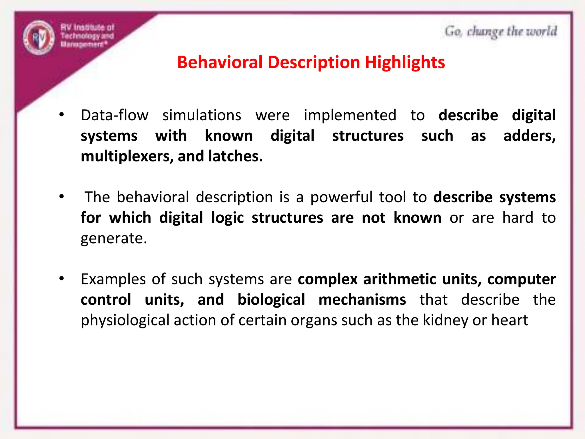
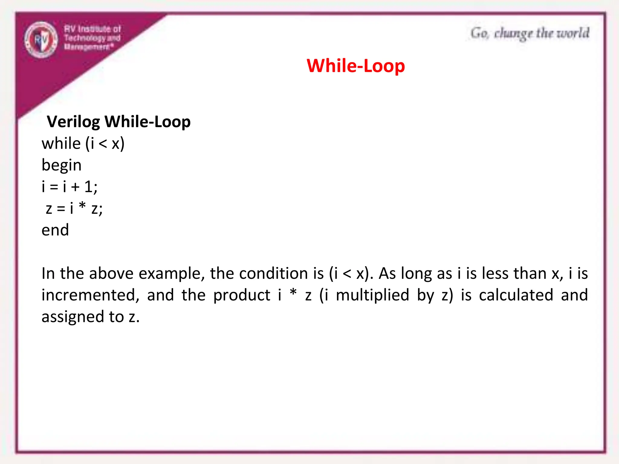
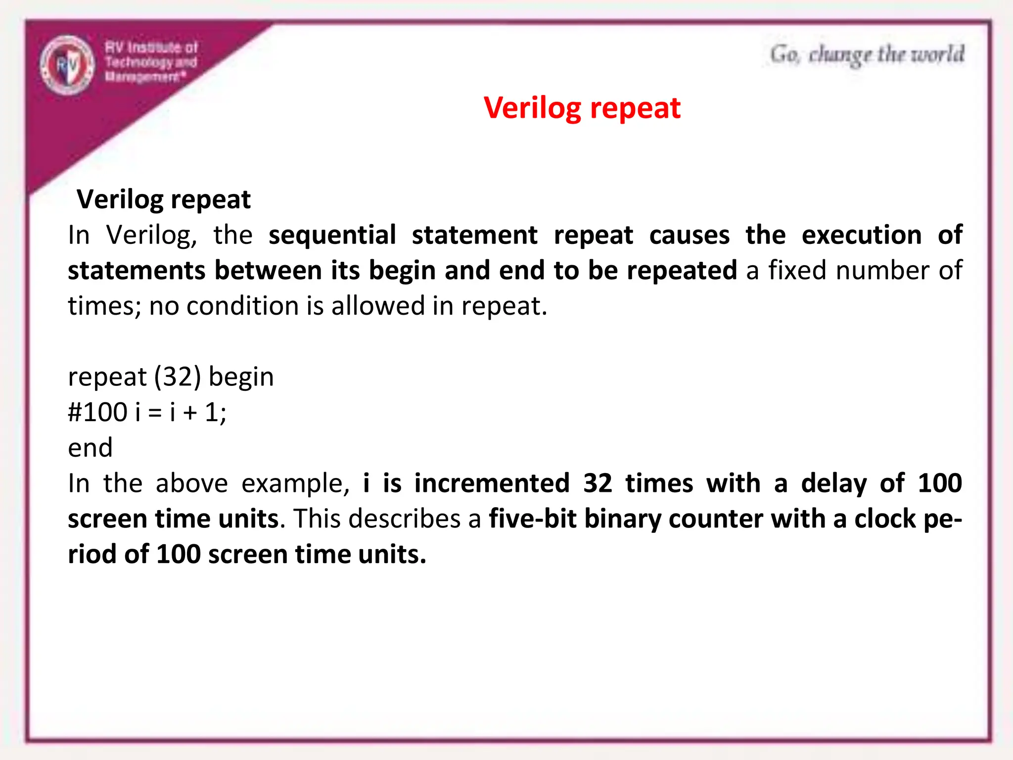
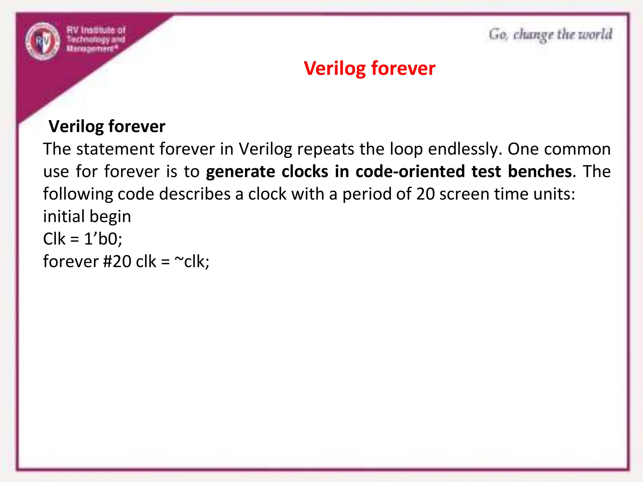
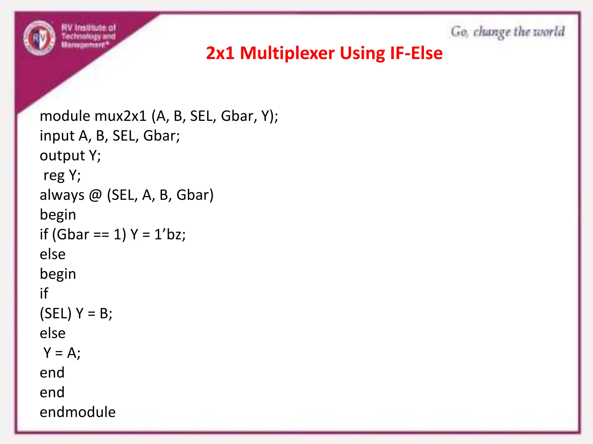
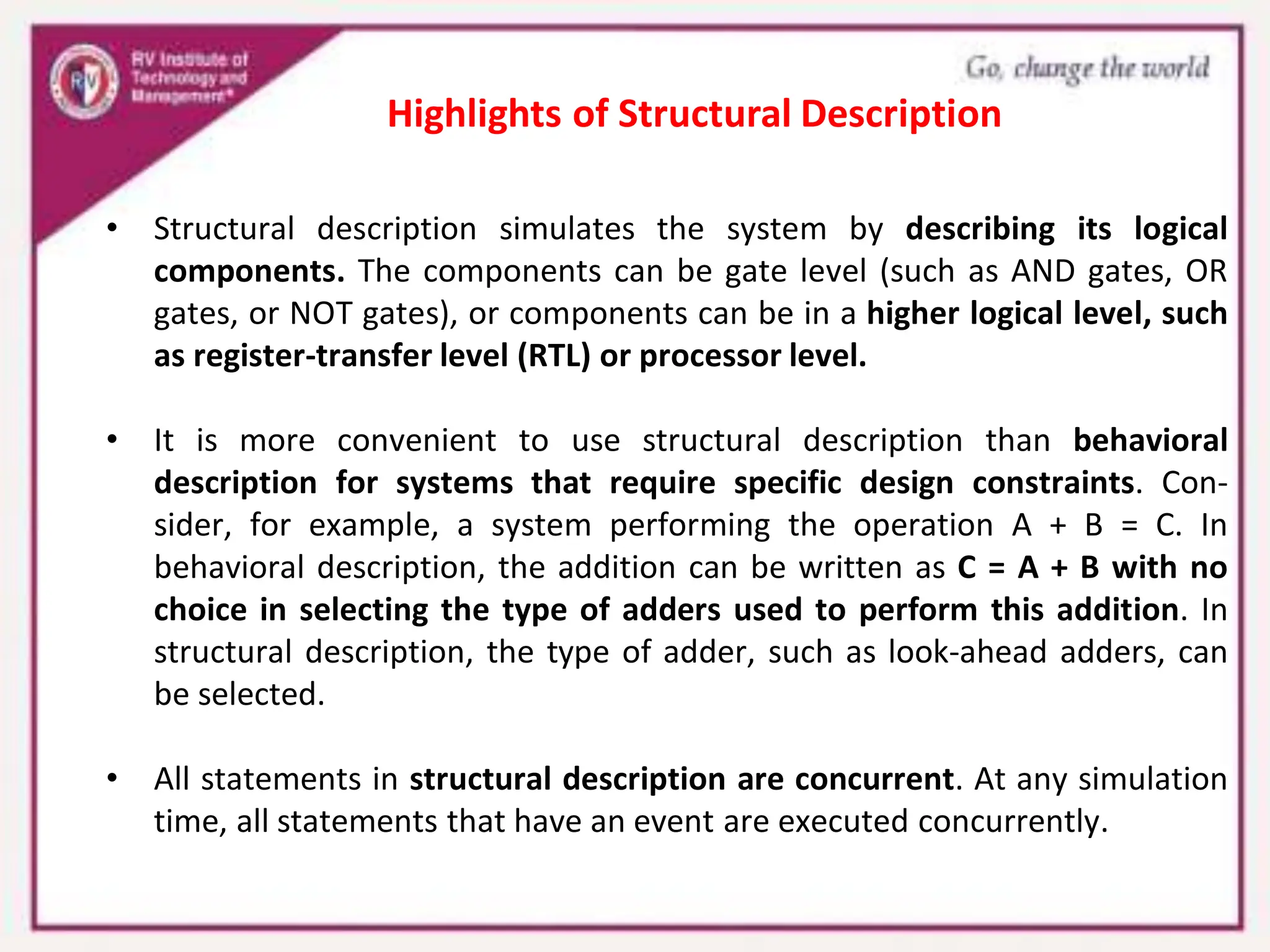
This document provides an overview of behavioral description in Verilog. It discusses:
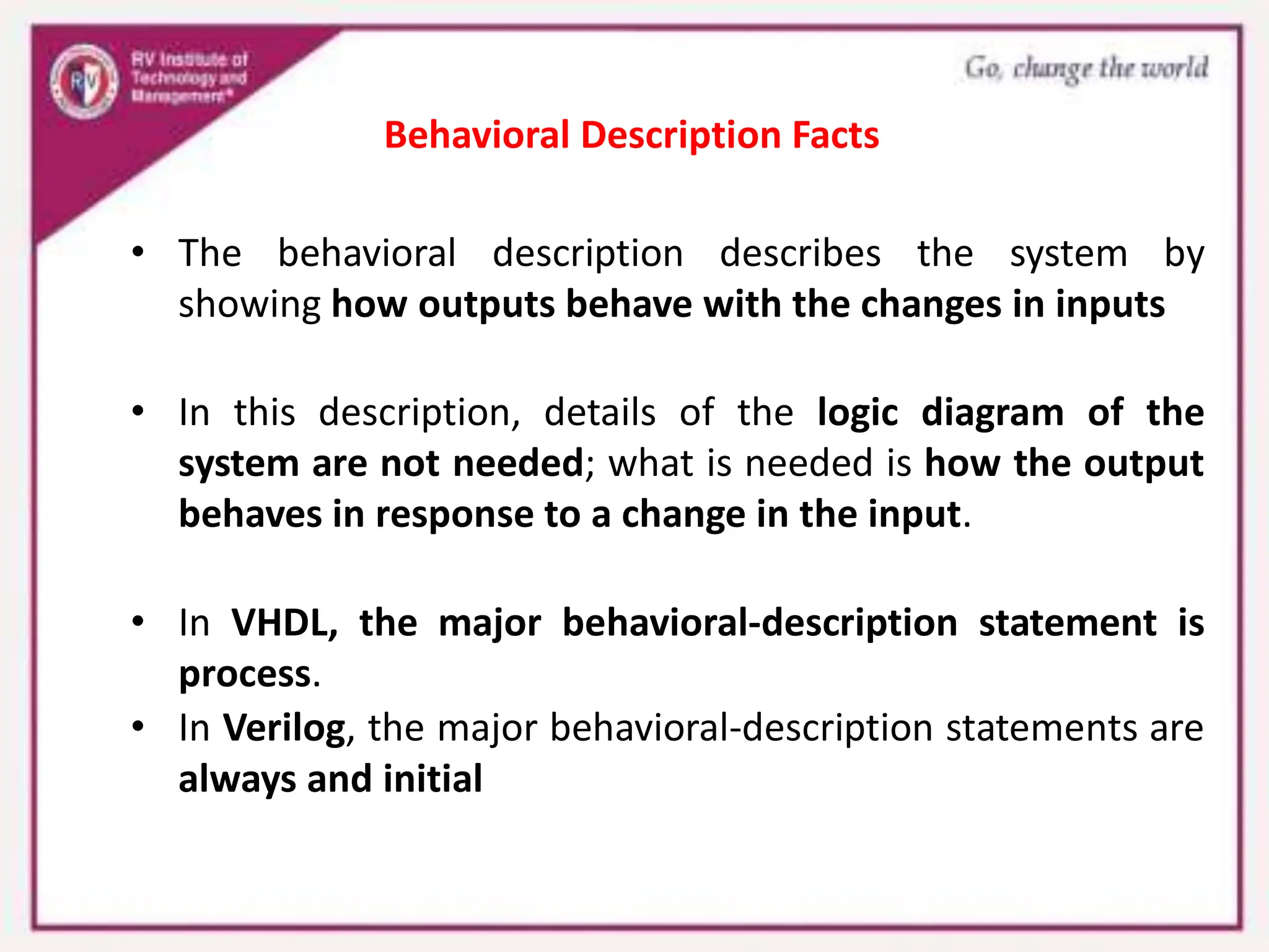
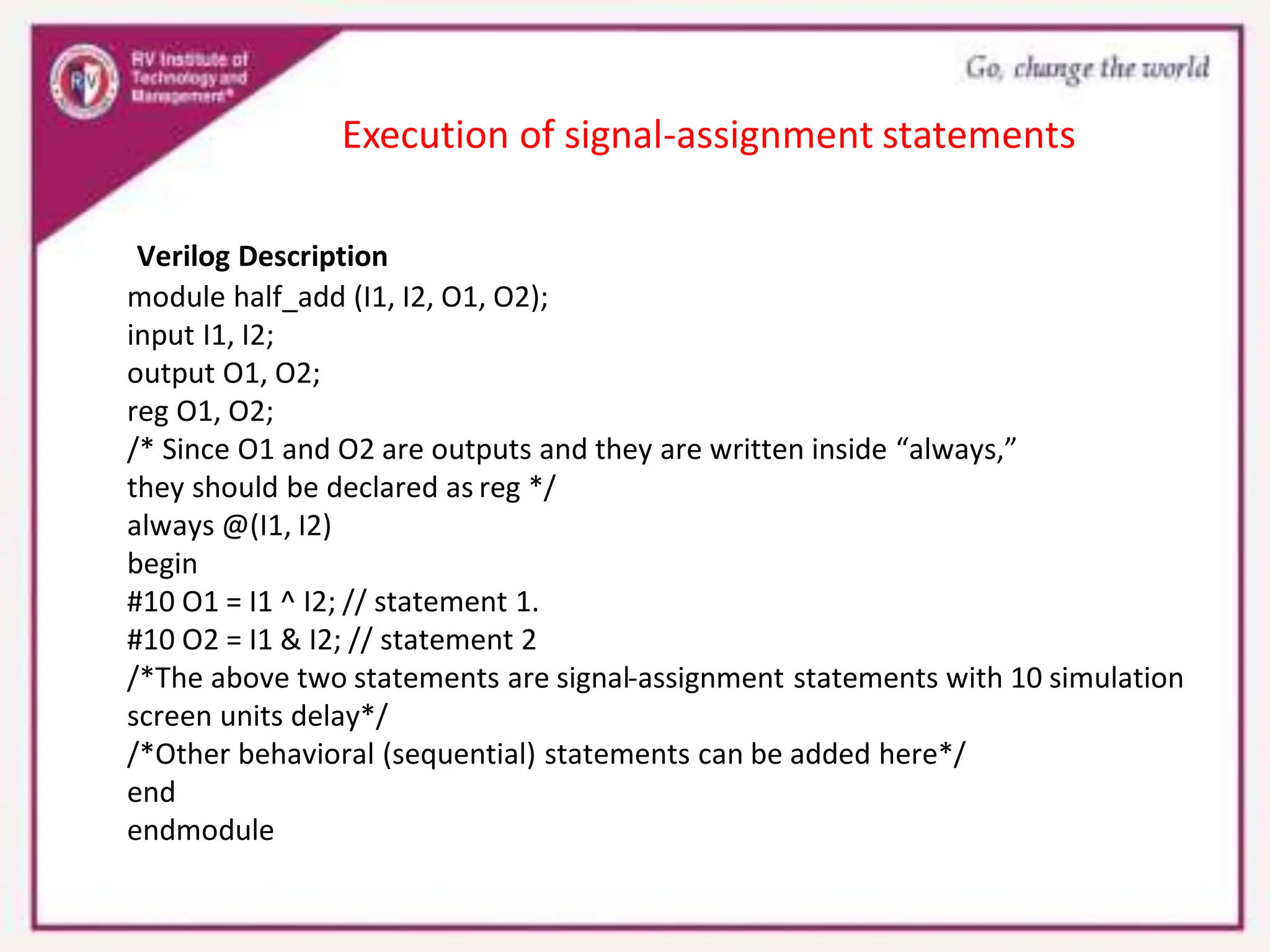
- Behavioral description describes how outputs behave in response to input changes without detailing logic diagrams.
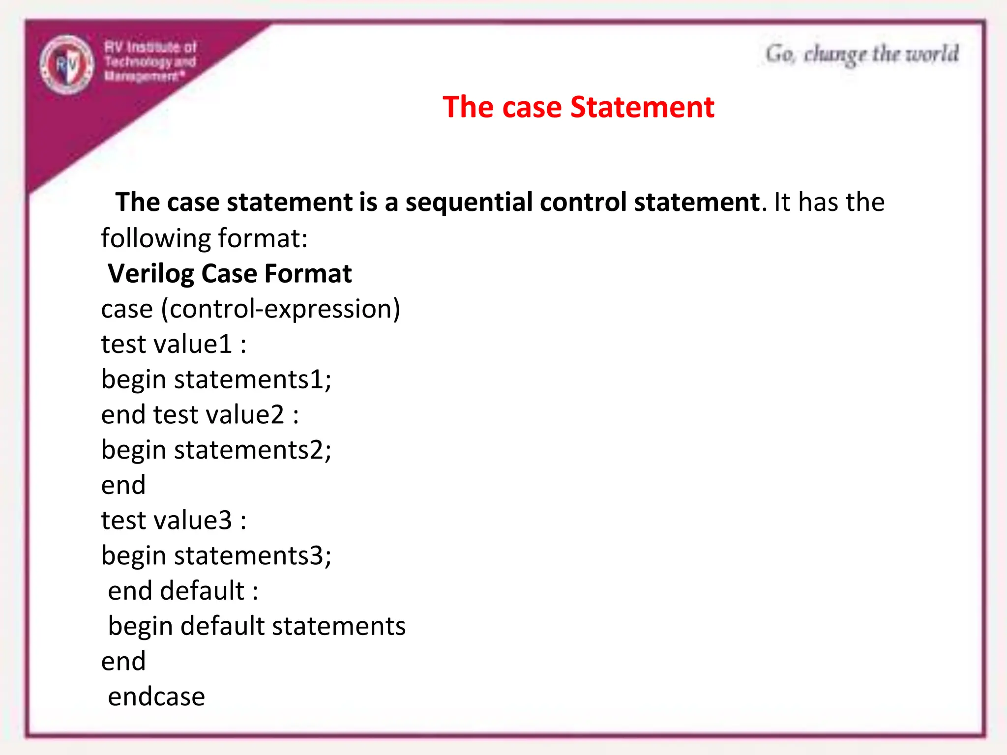
- Key behavioral description statements in Verilog are "always" and "initial".
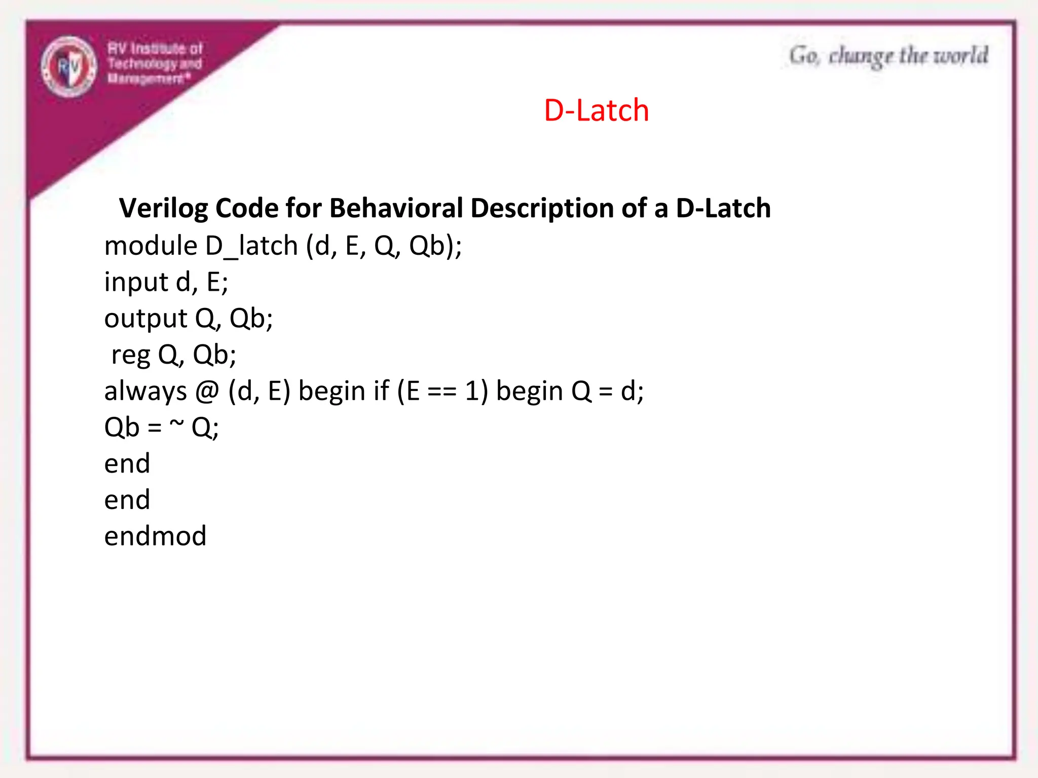
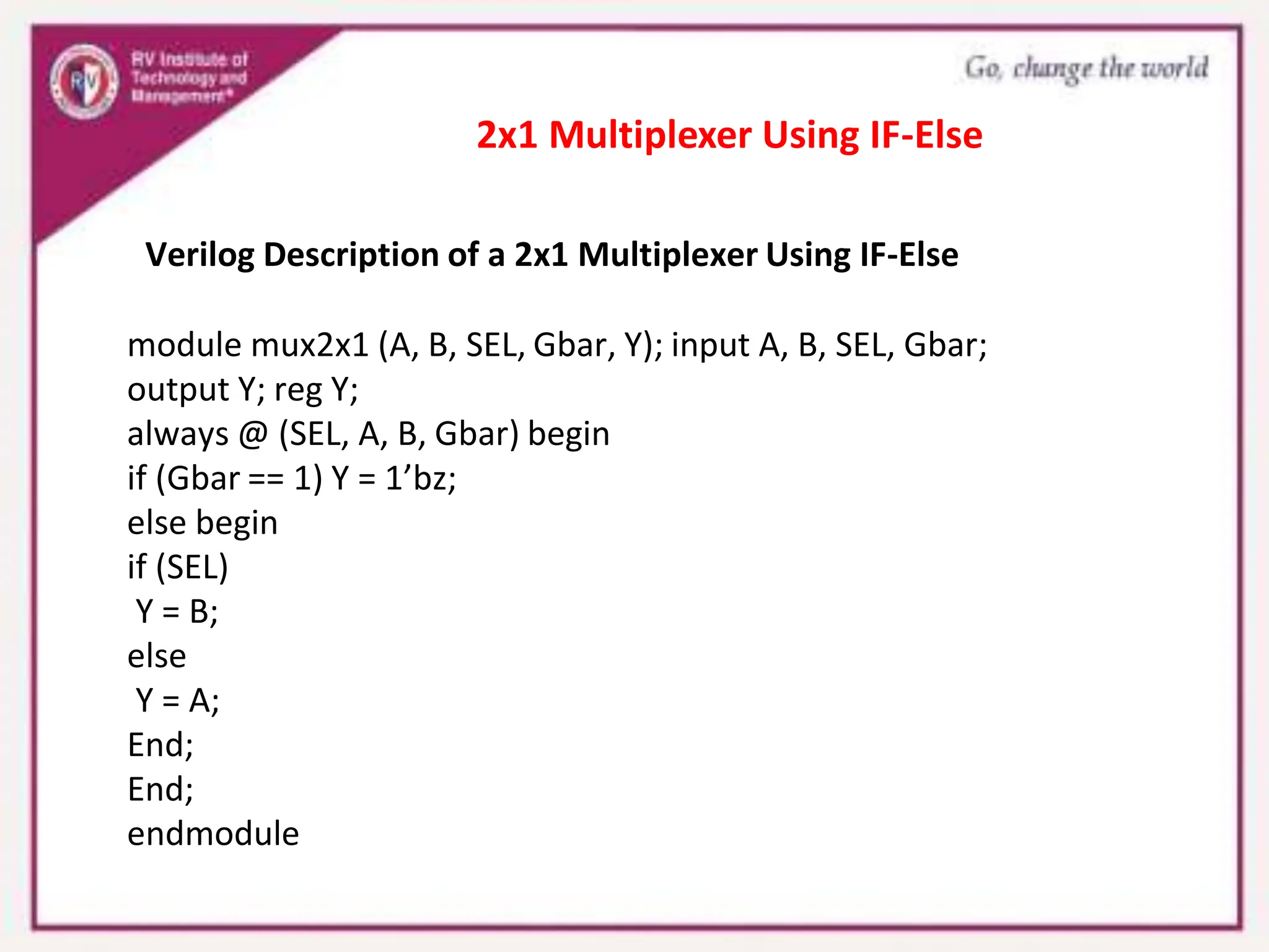
- Examples are provided to demonstrate behavioral description of half adders, D latches, multiplexers using if/else statements, and JK flip-flops using case statements.
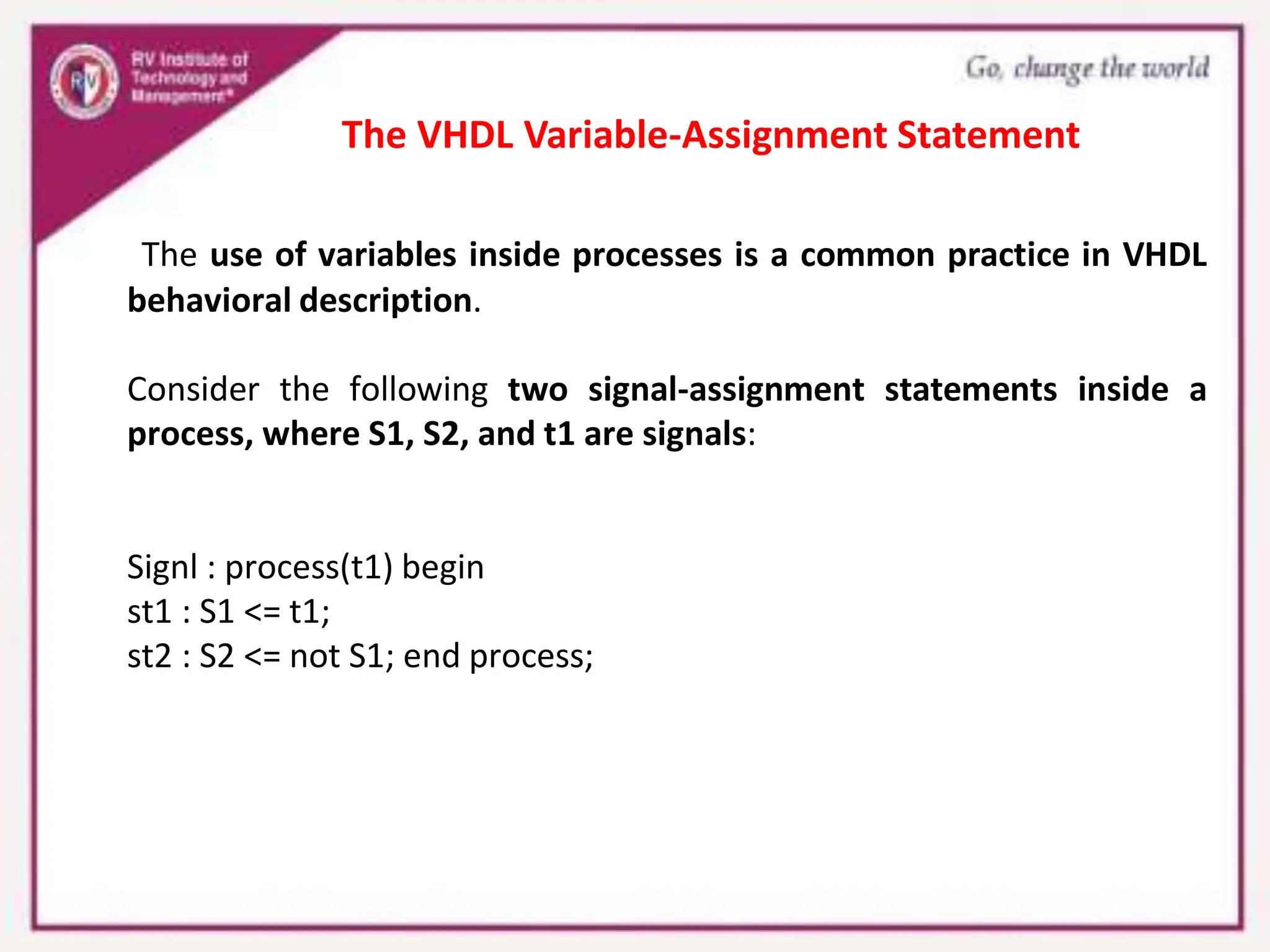
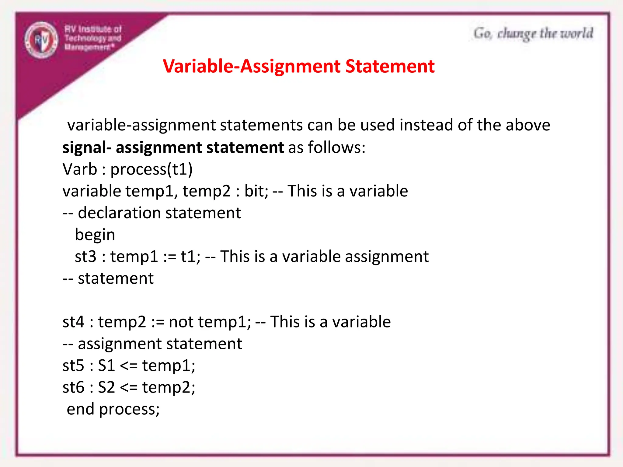
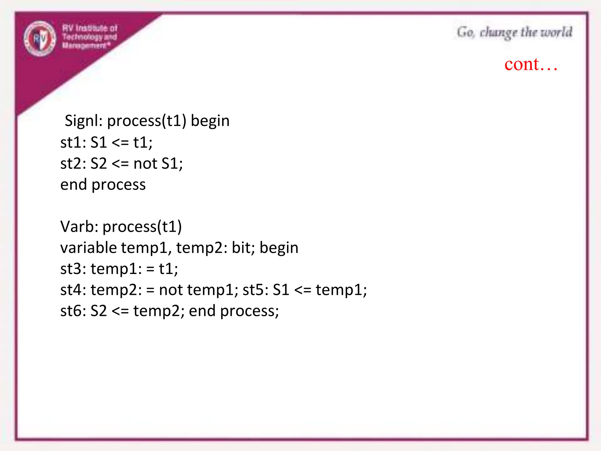
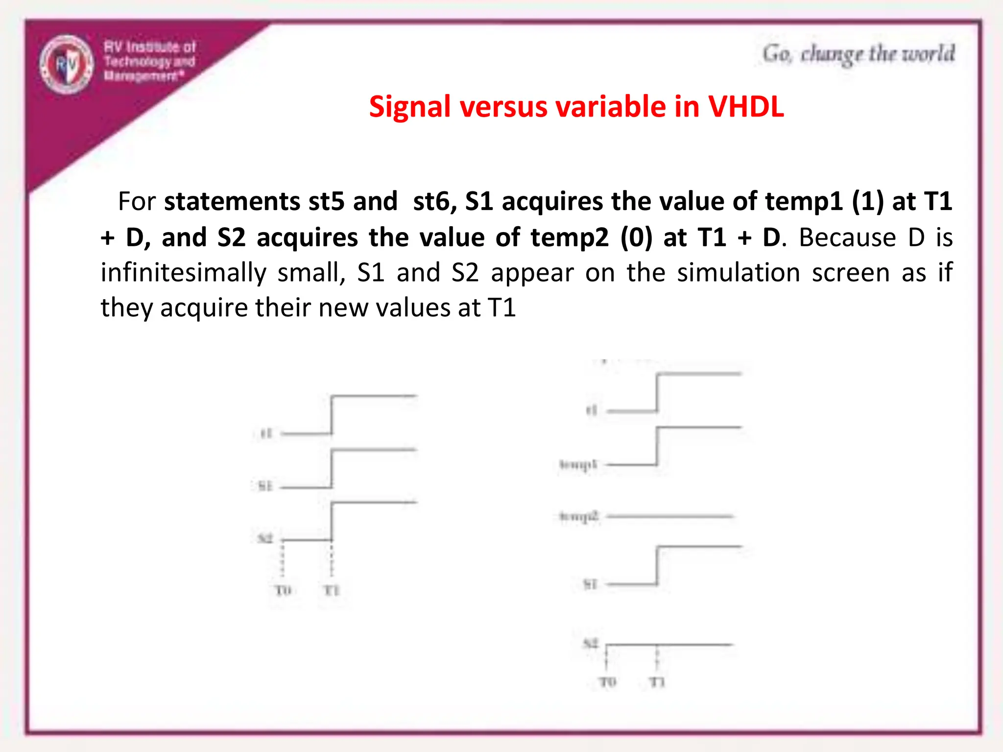
- Variables can be used instead of signals for immediate assignment in VHDL behavioral processes.


![module JK_FF (JK, clk, q, qb);
input [1:0] JK;
input clk;
output q, qb;
reg q, qb;
always @ (posedge clk)
begin
case (JK)
2’d0 : q = q;
2’d1 : q = 0;
2’d2 : q = 1;
2’d3 : q =~ q;
endcase
qb =~ q;
end
endmodule
Positive Edge-Triggered JK Flip-Flop Using the case
Statement](https://image.slidesharecdn.com/module5ppt-240407192343-beee1d4e/75/digital-system-design-using-verilog-Module-5-ppt-pptx-26-2048.jpg)

![Verilog For-Loop
for (i = 0; i <= 2; i = i + 1)
begin
if (temp[i] == 1’b1) begin
result = result + 2**i;
end
end
statement1; statement2; ....
The Loop Statement](https://image.slidesharecdn.com/module5ppt-240407192343-beee1d4e/75/digital-system-design-using-verilog-Module-5-ppt-pptx-29-2048.jpg)
![module countr_direct (clk, Z); input clk;
output [3:0] Z;
reg [3:0] Z; initial
Z = 4’b0000;
/*This initialization is needed if we want to start counting from 0000*/
always @ (posedge clk) Z = Z + 1;
endmodule
Verilog code describes a four-bit binary counter](https://image.slidesharecdn.com/module5ppt-240407192343-beee1d4e/75/digital-system-design-using-verilog-Module-5-ppt-pptx-33-2048.jpg)

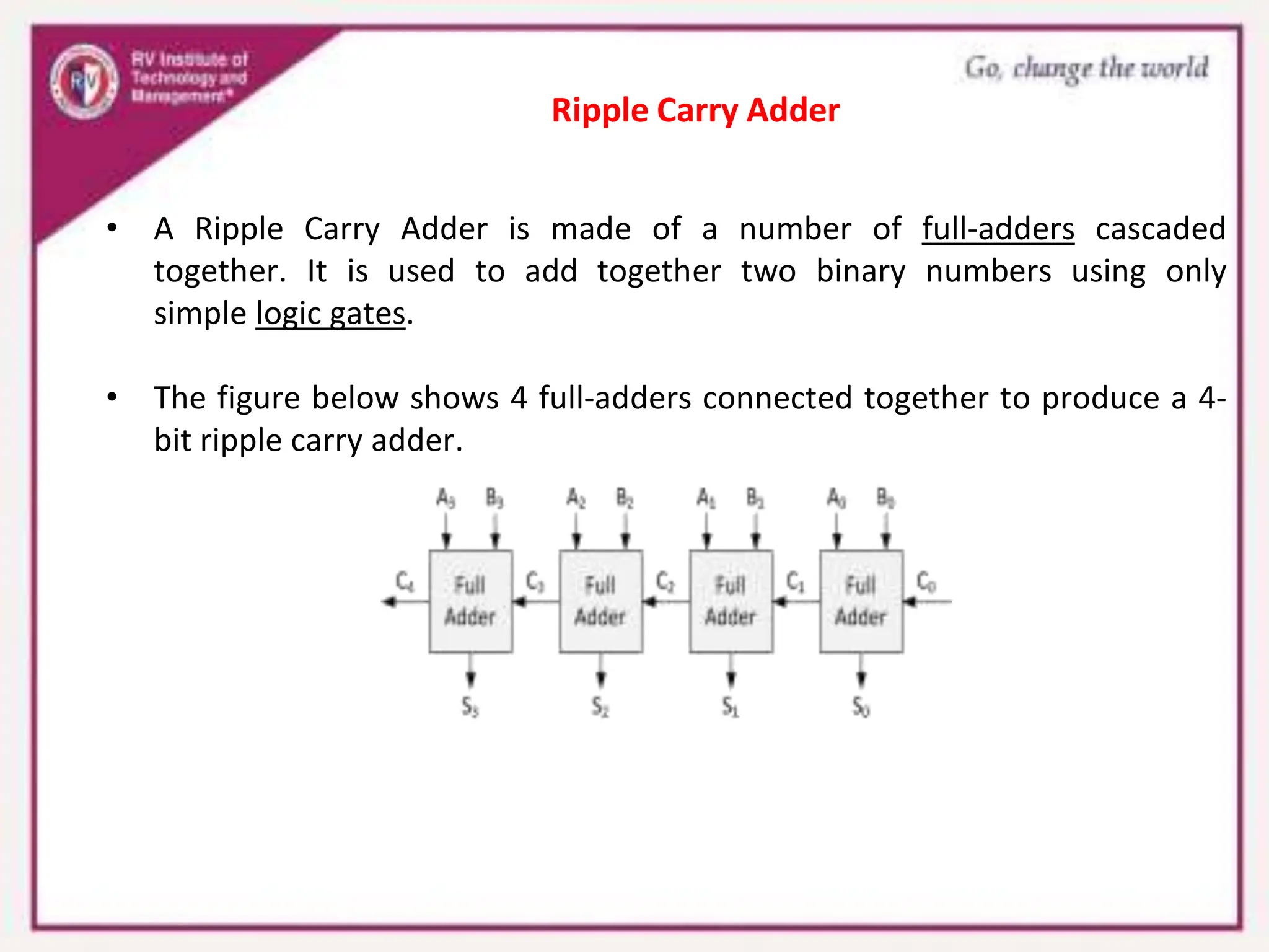
![Verilog code for 4-bit ripple-carry adder
module rippe_adder(X, Y, S, Co);
input [3:0] X, Y;// Two 4-bit inputs
output [3:0] S;
output Co;
wire w1, w2, w3;
// instantiating 4 1-bit full adders in Verilog
fulladder u1(X[0], Y[0], 1'b0, S[0], w1);
fulladder u2(X[1], Y[1], w1, S[1], w2);
fulladder u3(X[2], Y[2], w2, S[2], w3);
fulladder u4(X[3], Y[3], w3, S[3], Co);
endmodule
Ripple Carry Adder code](https://image.slidesharecdn.com/module5ppt-240407192343-beee1d4e/75/digital-system-design-using-verilog-Module-5-ppt-pptx-47-2048.jpg)