Downloaded 19 times


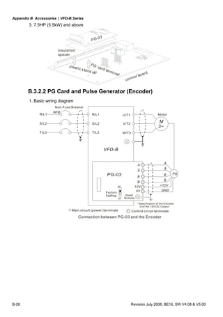
![Chapter 2 Installation and Wiring|VFD-B Series
Revision July 2008, BE16, SW V4.08 & V5.00 2-3
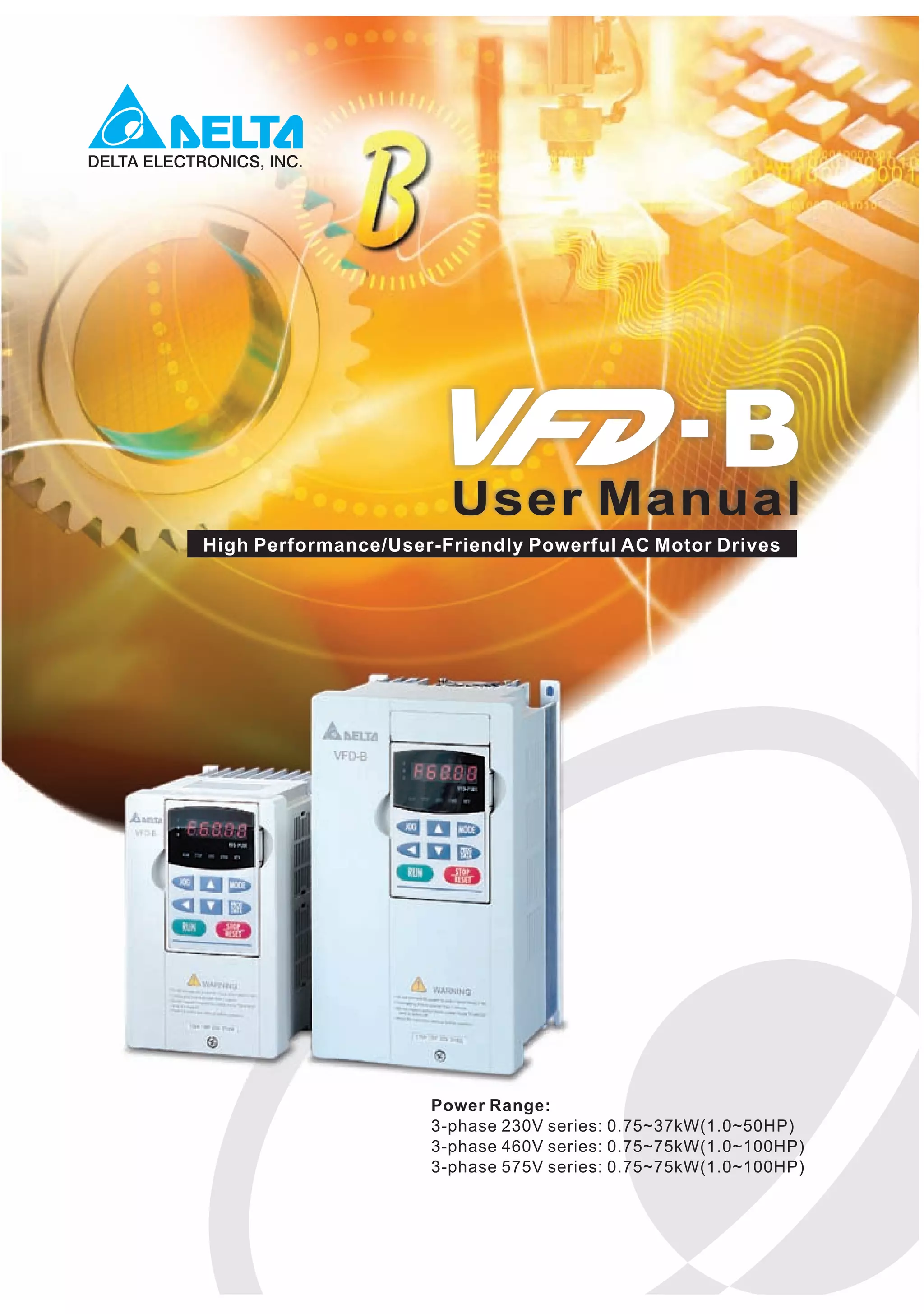
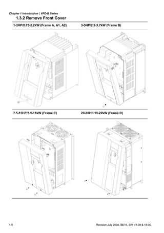
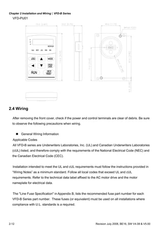
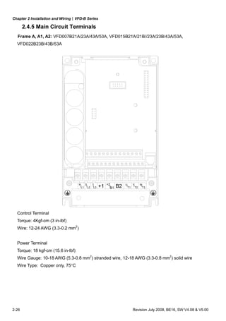
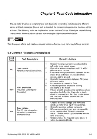
2.3 Dimensions
(Dimensions are in millimeter and [inch])
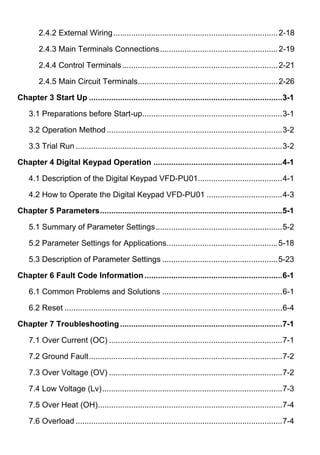
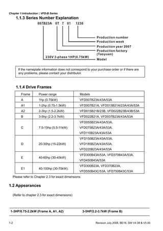
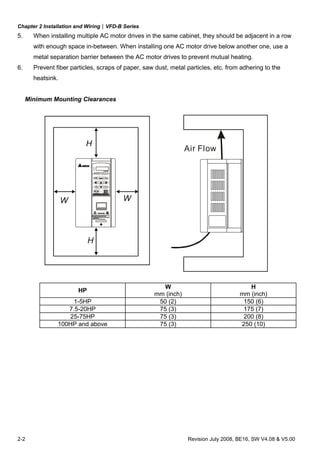
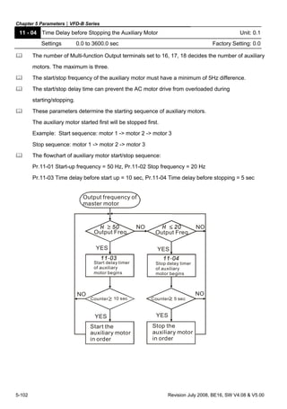
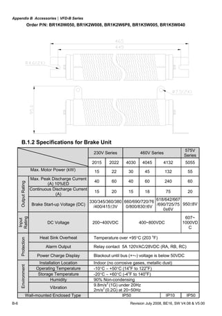
Frame A: VFD007B23A/43A/53A
5.5[0.22]108.0 [4.25]
118.0 [4.65]
173.0[6.81]
185.0[7.28]
5.5[0.22]
R2.75[0.11]
145.0 [5.71]
8.7[0.34]
22.0[ 0.87]
28.0[ 1.10](2X)](https://image.slidesharecdn.com/vfd-bmanualen-140613014201-phpapp01/85/Vfd-b-manual-en-20-320.jpg)
![Chapter 2 Installation and Wiring|VFD-B Series
2-4 Revision July 2008, BE16, SW V4.08 & V5.00
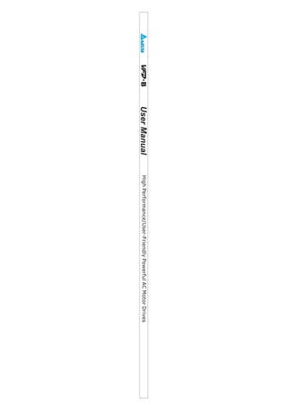
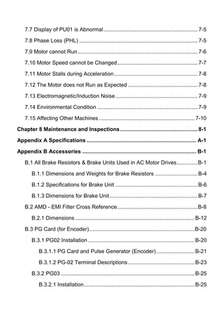
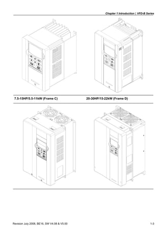
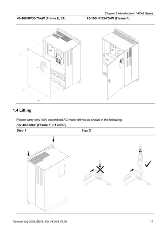
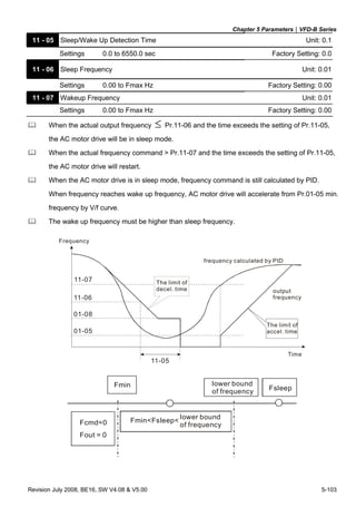
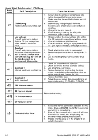
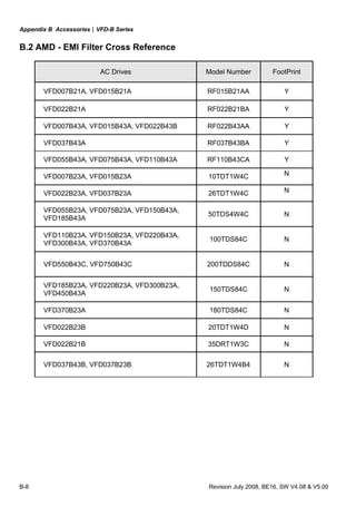
Frame A1: VFD007B21A, VFD015B21A/23A/43A/53A
5.5[0.22]
R2.75[0.11]
5.5[0.22]
185.0[7.28]
173.0[6.81]
160.0 [6.30]118.0 [4.65]
108.0 [4.25]
8.7[0.34]
28.0[ 1.10](2X)
22.0[ 0.87]](https://image.slidesharecdn.com/vfd-bmanualen-140613014201-phpapp01/85/Vfd-b-manual-en-21-320.jpg)
![Chapter 2 Installation and Wiring|VFD-B Series
Revision July 2008, BE16, SW V4.08 & V5.00 2-5
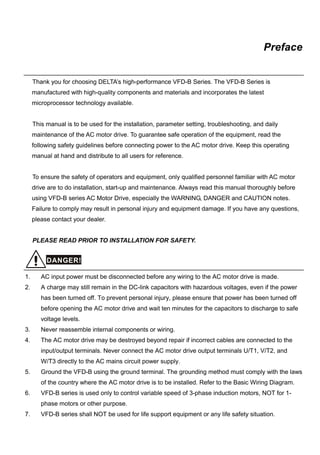
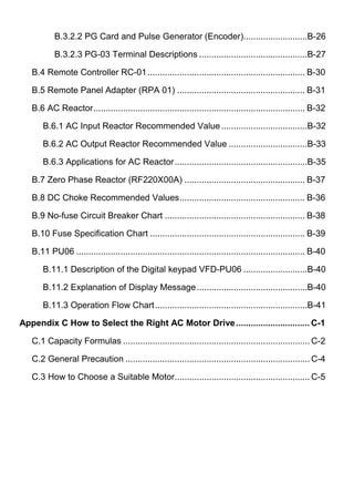
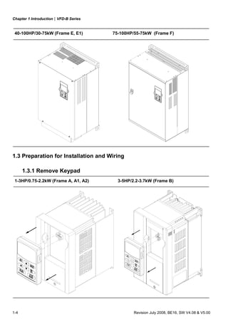
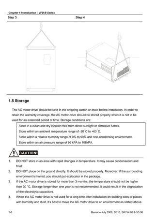
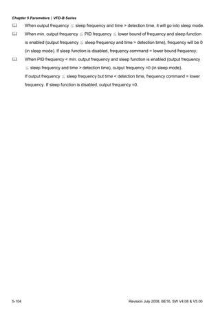
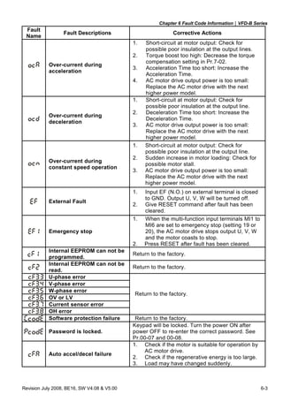
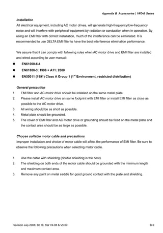
Frame A2: VFD015B21B/23B, VFD022B23B/43B/53A
5.5[0.22]
R2.75[0.11]
28.0[ 1.10](2X)
22.0[ 0.87]
8.7[0.34]
145.0 [5.71]118.0 [4.65]
108.0 [4.25] 5.5[0.22]
185.0[7.28]
173.0[6.81]](https://image.slidesharecdn.com/vfd-bmanualen-140613014201-phpapp01/85/Vfd-b-manual-en-22-320.jpg)
![Chapter 2 Installation and Wiring|VFD-B Series
2-6 Revision July 2008, BE16, SW V4.08 & V5.00
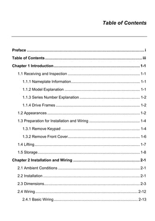
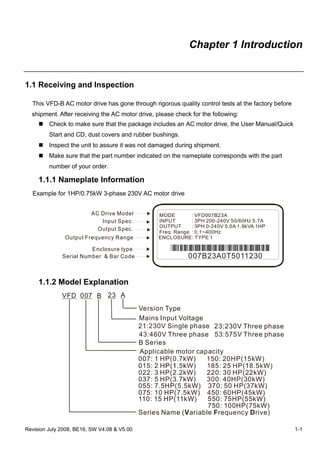
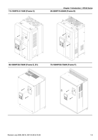
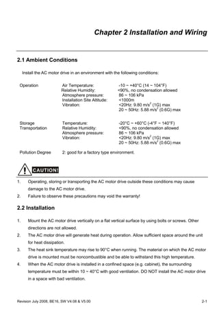
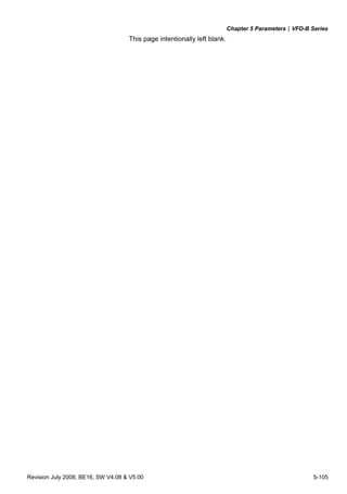
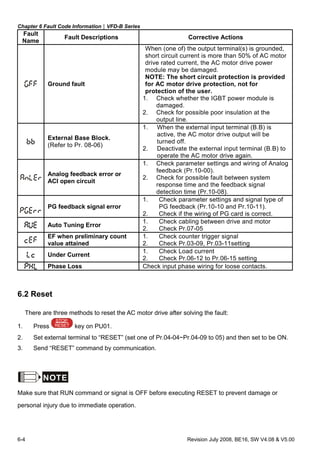
Frame B: VFD022B21A, VFD037B23A/43A/53A
11.3[0.44]
6.5[
0.26]
22.0[
0.87](2X)
28.0[
1.10](2X)
R3.25[R0.13]
6.5[0.26]
260.0[10.24]
UNIT : mm(inch)
135.0 [5.32] 160.2 [6.31]
244.3[9.63]
150.0 [5.91]](https://image.slidesharecdn.com/vfd-bmanualen-140613014201-phpapp01/85/Vfd-b-manual-en-23-320.jpg)
![Chapter 2 Installation and Wiring|VFD-B Series
Revision July 2008, BE16, SW V4.08 & V5.00 2-7
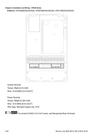
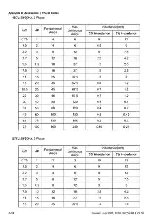
Frame C: VFD055B23A/43A/53A, VFD075B23A/43A/53A, VFD110B23A/43A/53A
200.0 [7.88]
323.0[12.72]
185.6 [7.31]
303.0[11.93]
R3.5
[R
0.14]
7.0 [0.28]
13.5[0.53]
183.2 [7.22]
7.0[
0.28]](https://image.slidesharecdn.com/vfd-bmanualen-140613014201-phpapp01/85/Vfd-b-manual-en-24-320.jpg)
![Chapter 2 Installation and Wiring|VFD-B Series
2-8 Revision July 2008, BE16, SW V4.08 & V5.00
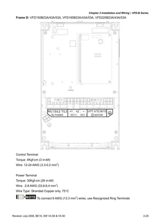
Frame D: VFD150B23A/43A/53A, VFD185B23A/43A/53A, VFD220B23A/43A/53A
13.0[0.51]
10.0 [0.39]
R5.0[R0.20]
403.8[15.90]
384.0[15.12]
42.0[ 1.65](2X)
250.0 [9.84]
226.0 [8.90]
28.0[
1.10]
205.4 [8.08]
10.0 [ 0.39]](https://image.slidesharecdn.com/vfd-bmanualen-140613014201-phpapp01/85/Vfd-b-manual-en-25-320.jpg)
![Chapter 2 Installation and Wiring|VFD-B Series
Revision July 2008, BE16, SW V4.08 & V5.00 2-9
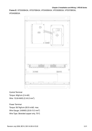
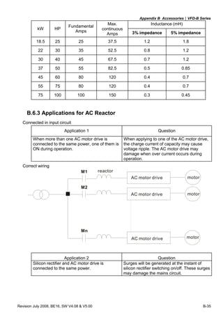
Frame E: VFD300B43A/53A, VFD370B43A/53A, VFD450B43A/53A
335.0 [13.19]
370.0 [14.57] 260.0 [10.24]
589.0[23.19]
560.0[22.05]
18.0 [0.71]
132.5 [5.22]
R6.5[0.25]
13.0[0.51]
21.0[0.83]](https://image.slidesharecdn.com/vfd-bmanualen-140613014201-phpapp01/85/Vfd-b-manual-en-26-320.jpg)
![Chapter 2 Installation and Wiring|VFD-B Series
2-10 Revision July 2008, BE16, SW V4.08 & V5.00
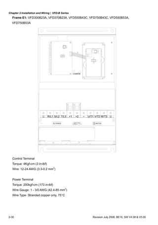
Frame E1: VFD300B23A, VFD370B23A, VFD550B43C/53A, VFD750B43C/53A
132.5 [5.22]
18.0 [0.71]21.0[0.83]
335.0 [13.19]
370.0 [14.57] 260.0 [10.24]
589.0[23.19]
560.0[22.05]
R6.5[0.25]
13.0[0.51]
595.0[23.43]](https://image.slidesharecdn.com/vfd-bmanualen-140613014201-phpapp01/85/Vfd-b-manual-en-27-320.jpg)
![Chapter 2 Installation and Wiring|VFD-B Series
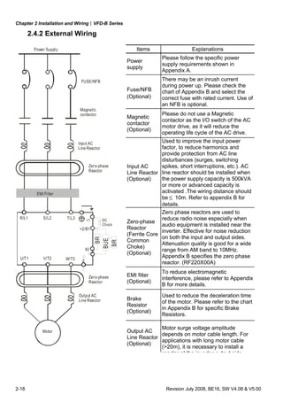
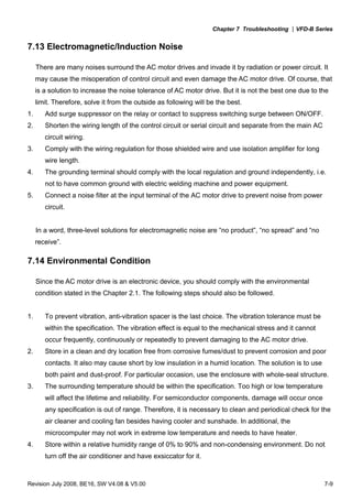
2-20 Revision July 2008, BE16, SW V4.08 & V5.00
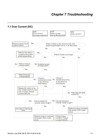
DO NOT connect phase-compensation capacitors or surge absorbers at the output terminals
of AC motor drives.
With long motor cables, high capacitive switching current peaks can cause over-current, high
leakage current or lower current readout accuracy. To prevent this, the motor cable should
be less than 20m for 3.7kW models and below. And the cable should be less than 50m for
5.5kW models and above. For longer motor cables use an AC output reactor.
Use a well-insulated motor, suitable for inverter operation.
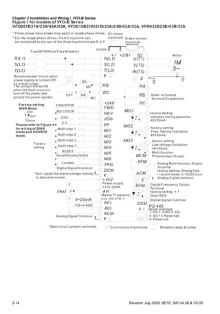
Terminals [+1, +2] for connecting DC reactor
+1
Jumper
DC reactor
To improve the power factor and reduce harmonics, connect a DC reactor between terminals
[+1, +2]. Please remove the jumper before connecting the DC reactor.
NOTE Models of 15kW and above have a built-in DC reactor.
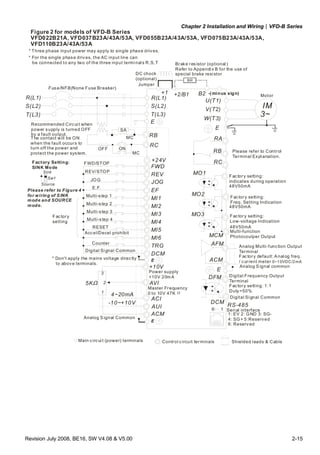
Terminals [+2/B1, B2] for connecting brake resistor and terminals [+1, +2/B1] for connecting
external brake unit
B2
VFDB
-(minus sign)
BR
BR
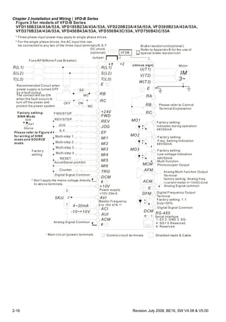
Connect a brake resistor or brake unit in applications with frequent deceleration ramps, short
deceleration time, too low brake torque or requiring increased brake torque.
If the AC motor drive has a built-in brake chopper (all models of 11kW and below), connect
the external brake resistor to the terminals [+2/B1, B2].
Models of 15kW and above don’t have a built-in brake chopper. Please connect an external
optional brake unit (VFDB-series) and brake resistor. Refer to VFDB series user manual for
details.
Connect the terminals [+(P), -(N)] of the brake unit to the AC motor drive terminals
[+2(+2/B1), (-)]. The length of wiring should be less than 5m with twisted cable.
When not used, please leave the terminals [+2/B1, -] open.](https://image.slidesharecdn.com/vfd-bmanualen-140613014201-phpapp01/85/Vfd-b-manual-en-37-320.jpg)
![Chapter 2 Installation and Wiring|VFD-B Series
Revision July 2008, BE16, SW V4.08 & V5.00 2-21
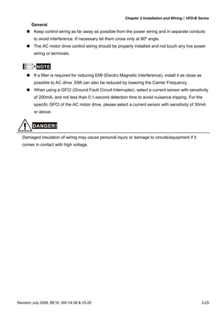
WARNING!
1. Short-circuiting [B2] or [-] to [+2/B1] can damage the AC motor drive.
Grounding terminals ( )
Make sure that the leads are connected correctly and the AC drive is properly grounded.
(Ground resistance should not exceed 0.1Ω.)
Use ground leads that comply with local regulations and keep them as short as possible.
Multiple VFD-B units can be installed in one location. All the units should be grounded
directly to a common ground terminal, as shown in the figure below. Ensure there are no
ground loops.
goodexcellent not allowed
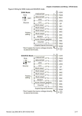
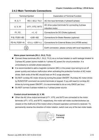
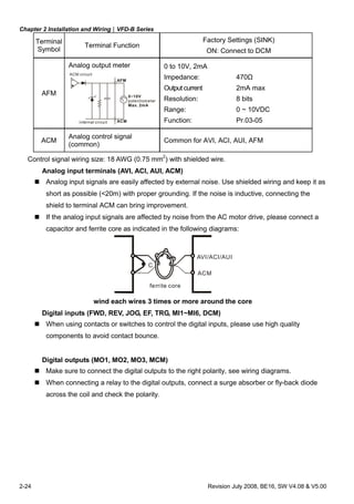
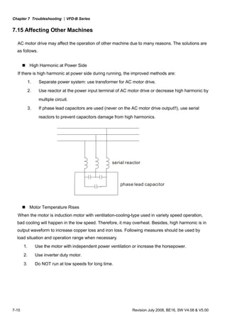
2.4.4 Control Terminals
Circuit diagram for digital inputs (SINK current 16mA.)
+24
SINK Mode
multi-input
terminal
Internal Circuit
DCM
+24V
Multi-Input
Terminal
DCM
Internal Circuit
SOURCE Mode
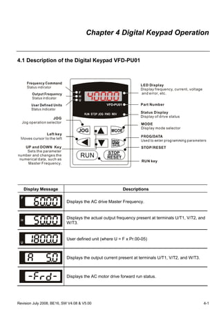
Terminal symbols and functions
Terminal
Symbol
Terminal Function
Factory Settings (SINK)
ON: Connect to DCM
FWD Forward-Stop command
ON: Run in FWD direction
OFF: Stop acc. to Stop Method
REV Reverse-Stop command
ON: Run in REV direction
OFF: Stop acc. to Stop Method](https://image.slidesharecdn.com/vfd-bmanualen-140613014201-phpapp01/85/Vfd-b-manual-en-38-320.jpg)
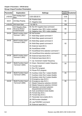
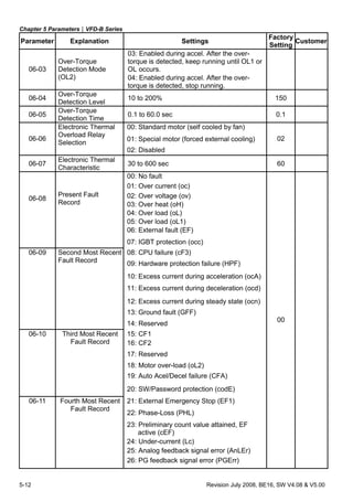
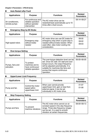
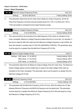
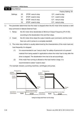
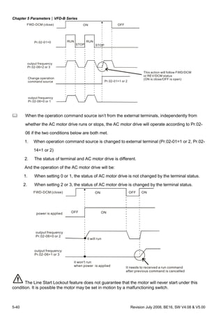
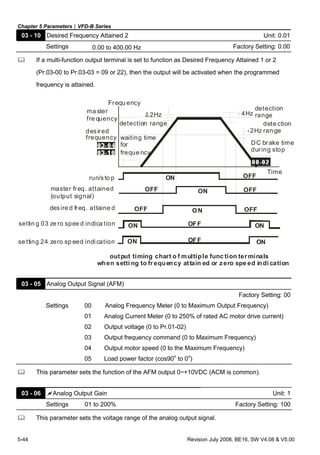
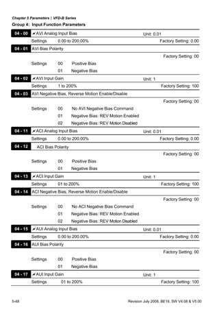
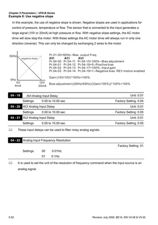
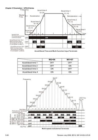
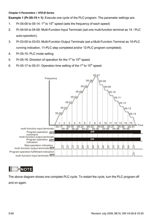
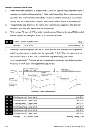
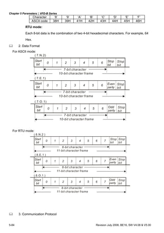
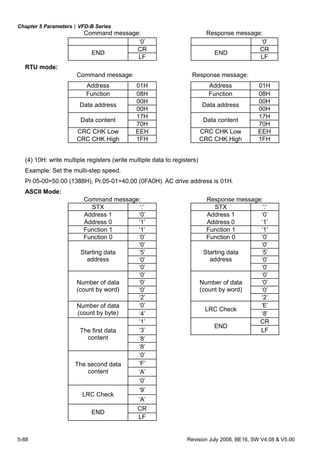
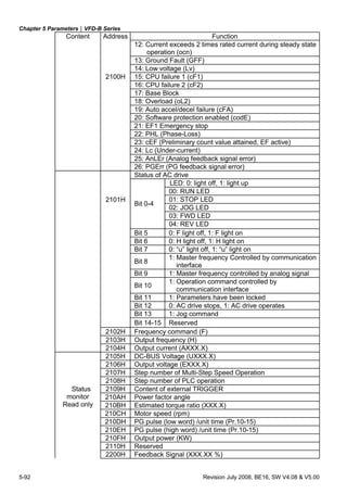
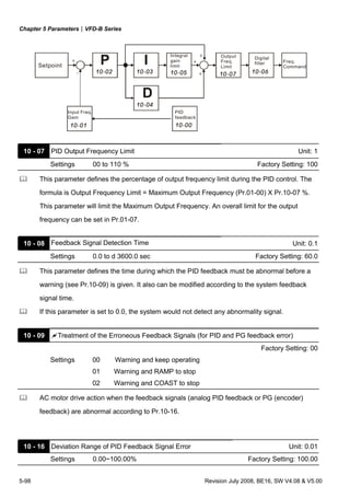
![Chapter 5 Parameters|VFD-B Series
5-94 Revision July 2008, BE16, SW V4.08 & V5.00
Exception
code Explanation
10
Communication time-out:
If Pr.09-03 is not equal to 0.0, Pr.09-02=00~02, and there is no
communication on the bus during the Time Out detection period (set
by Pr.09-03), “cE10” will be shown on the keypad.
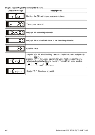
3.7 Communication program of PC:
The following is a simple example of how to write a communication program for Modbus ASCII
mode on a PC by C language.
#include<stdio.h>
#include<dos.h>
#include<conio.h>
#include<process.h>
#define PORT 0x03F8 /* the address of COM1 */
/* the address offset value relative to COM1 */
#define THR 0x0000
#define RDR 0x0000
#define BRDL 0x0000
#define IER 0x0001
#define BRDH 0x0001
#define LCR 0x0003
#define MCR 0x0004
#define LSR 0x0005
#define MSR 0x0006
unsigned char rdat[60];
/* read 2 data from address 2102H of AC drive with address 1 */
unsigned char tdat[60]={':','0','1','0','3','2','1','0',’2', '0','0','0','2','D','7','r','n'};
void main(){
int i;
outportb(PORT+MCR,0x08); /* interrupt enable */
outportb(PORT+IER,0x01); /* interrupt as data in */
outportb(PORT+LCR,(inportb(PORT+LCR) | 0x80));
/* the BRDL/BRDH can be access as LCR.b7==1 */
outportb(PORT+BRDL,12); /* set baudrate=9600, 12=115200/9600*/
outportb(PORT+BRDH,0x00);
outportb(PORT+LCR,0x06); /* set protocol, <7,N,2>=06H, <7,E,1>=1AH, <7,O,1>=0AH,
<8,N,2>=07H, <8,E,1>=1BH, <8,O,1>=0BH */
for(i=0;i<=16;i++){](https://image.slidesharecdn.com/vfd-bmanualen-140613014201-phpapp01/85/Vfd-b-manual-en-151-320.jpg)
![Chapter 5 Parameters|VFD-B Series
Revision July 2008, BE16, SW V4.08 & V5.00 5-95
while(!(inportb(PORT+LSR) & 0x20)); /* wait until THR empty */
outportb(PORT+THR,tdat[i]); /* send data to THR */ }
i=0;
while(!kbhit()){
if(inportb(PORT+LSR) & 0x01){ /* b0==1, read data ready */
rdat[i++]=inportb(PORT+RDR); /* read data form RDR */
} } }
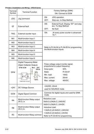
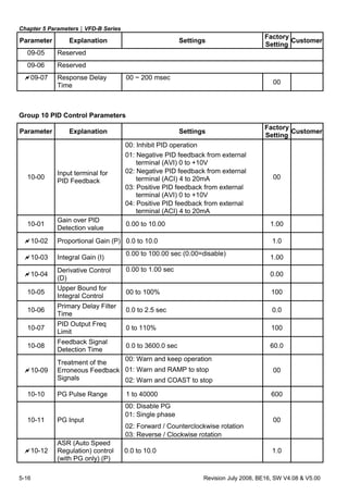
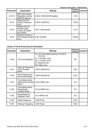
09 - 05 Reserved
09 - 06 Reserved
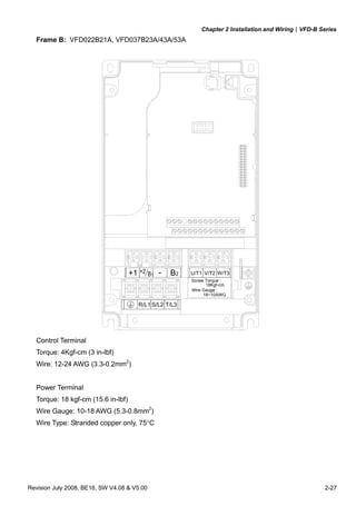
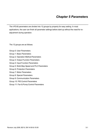
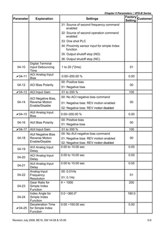
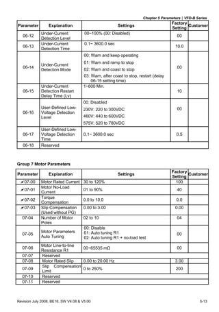
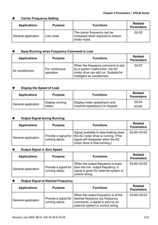
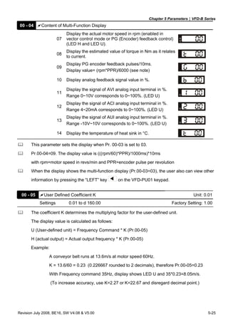
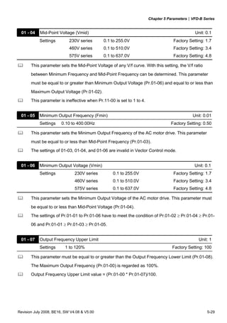
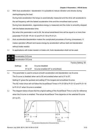
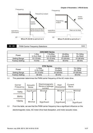
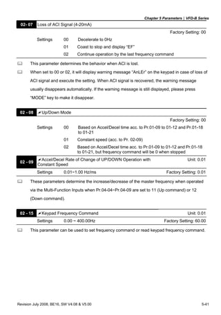
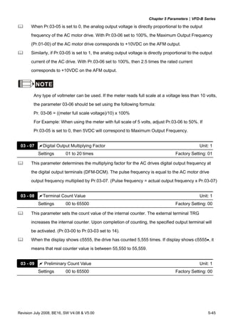
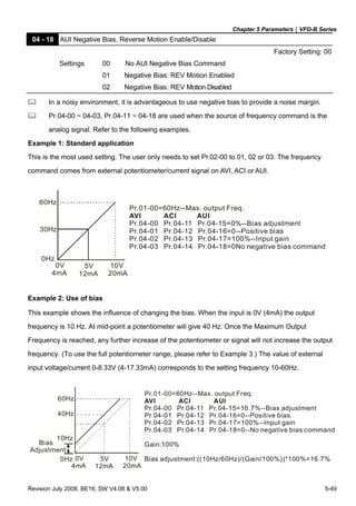
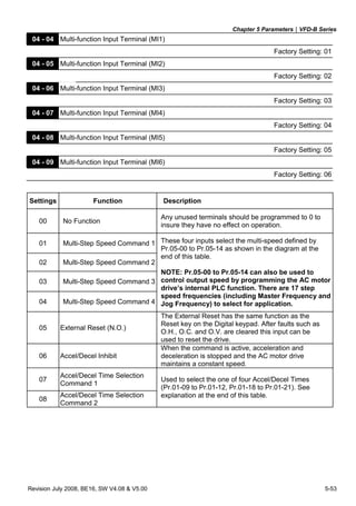
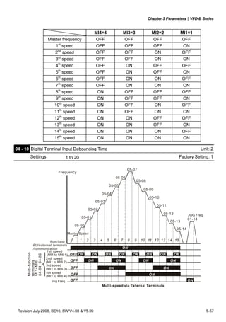
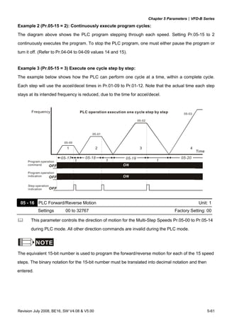
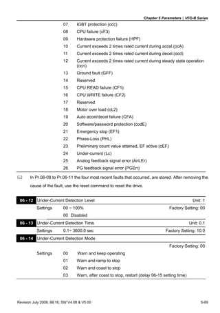
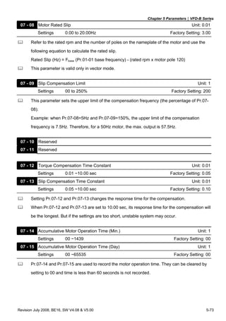
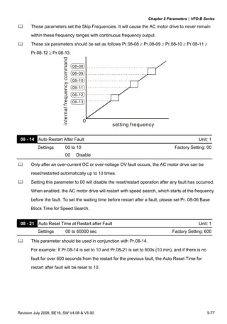
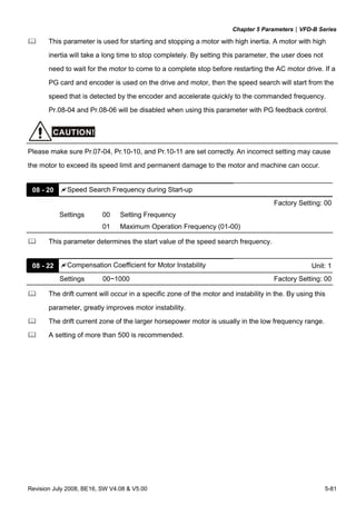
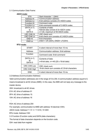
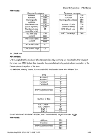
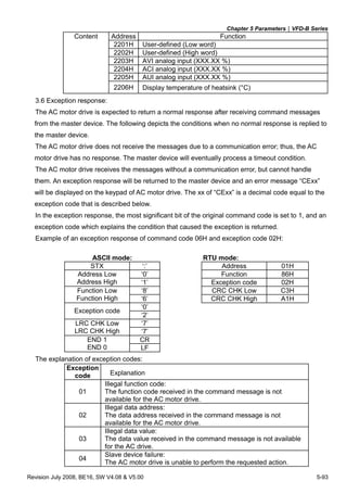
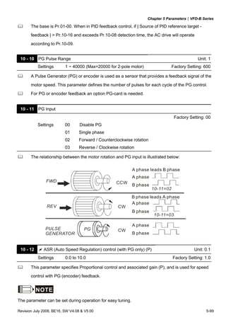
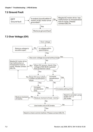
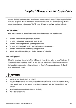
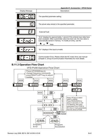
09 - 07 Response Delay Time Unit: 2
Settings 00 ~ 200 msec Factory Setting: 00
This parameter is the response delay time after AC drive receives communication command
as shown in the following.
RS485 BUS
PC or PLC command
Handling time
of AC drive
Response Delay Time
Response Message of AC Drive
Max.: 6msec
Pr.09-07
* This parameter is only for firmware version 4.01 and higher.](https://image.slidesharecdn.com/vfd-bmanualen-140613014201-phpapp01/85/Vfd-b-manual-en-152-320.jpg)
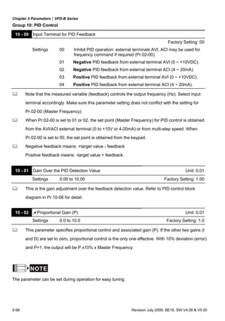
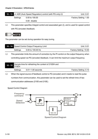

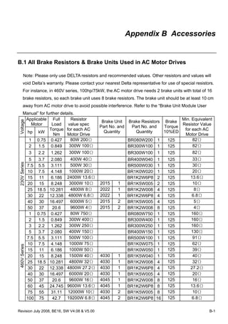
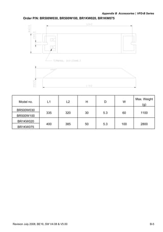
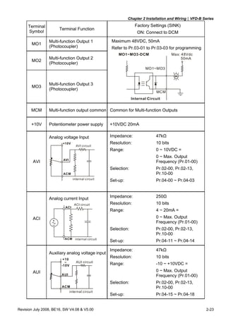
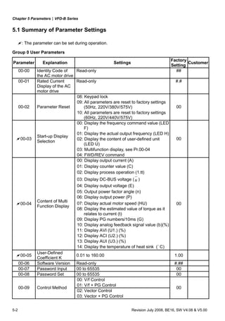
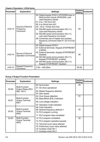
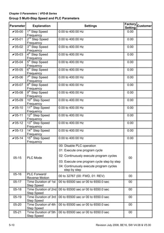
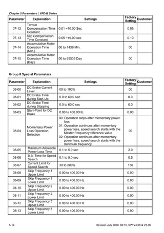
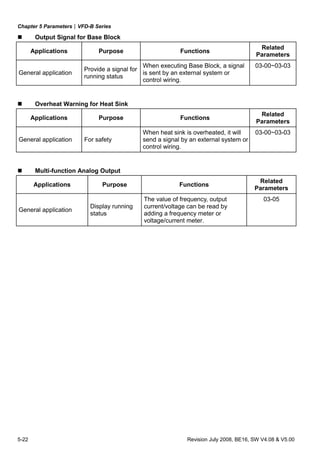
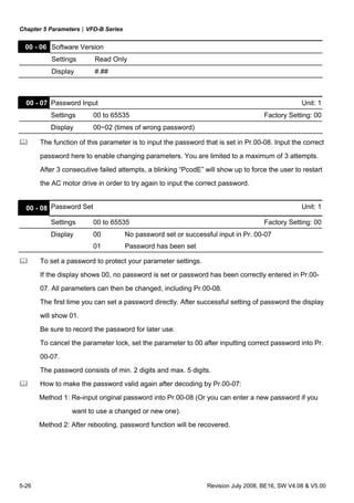
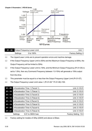
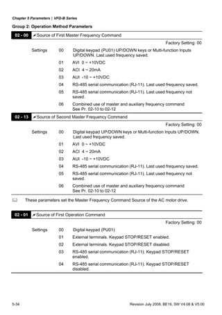
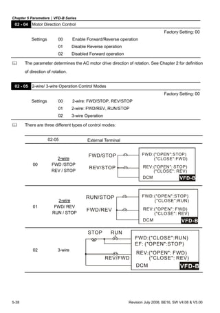
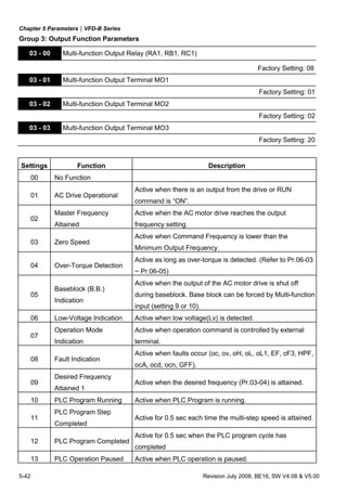
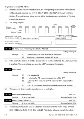
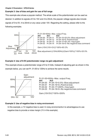
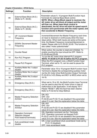
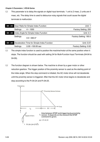
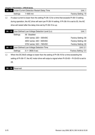
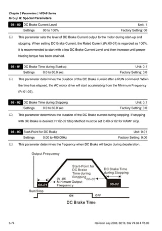
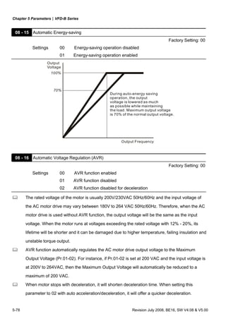
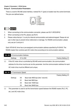
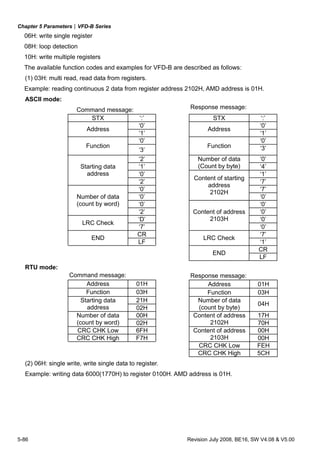
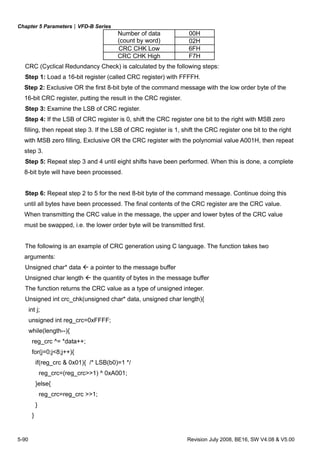
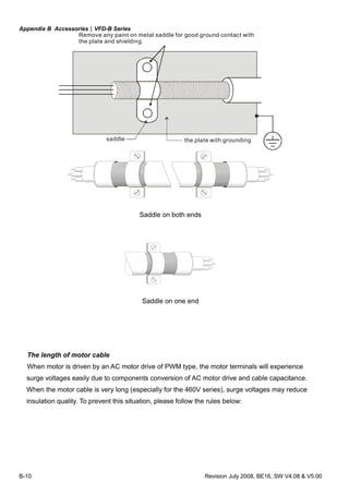
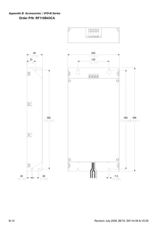
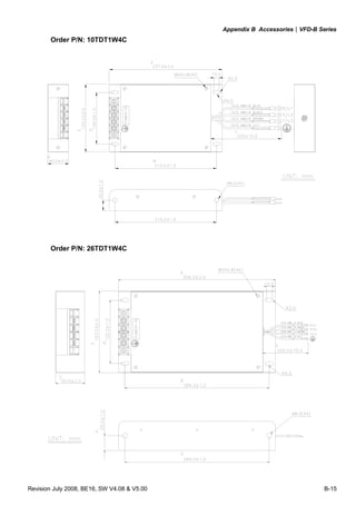
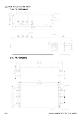
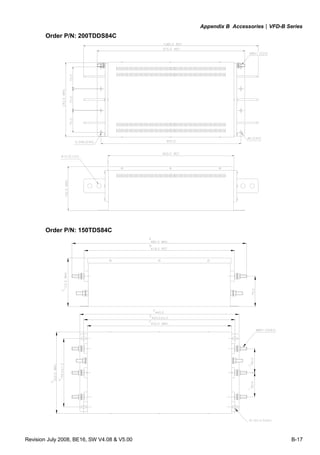
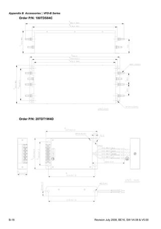
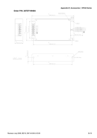
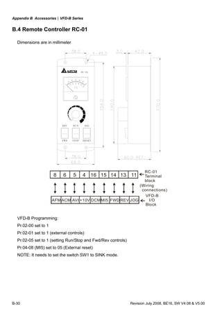
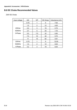
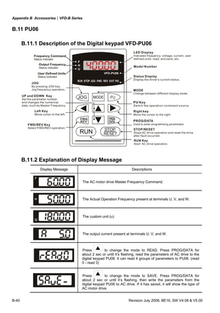
![Appendix B Accessories|VFD-B Series
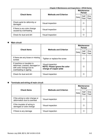
Revision July 2008, BE16, SW V4.08 & V5.00 B-7
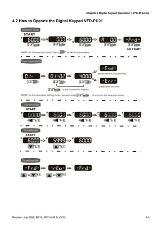
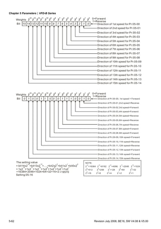
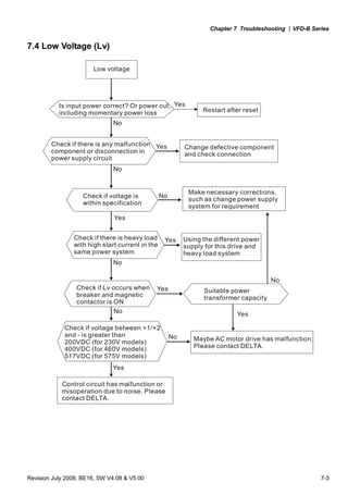
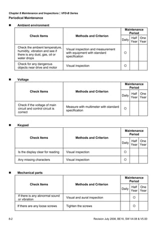
B.1.3 Dimensions for Brake Unit
(Dimensions are in millimeter[inch])
80.0 [3.15]
121.0 [4.76]
189.5[7.46]
200.0[7.87]
130.0 [5.12]
R3.3 [R0.13]
ACT.
YELLOW
CHARGE
GREEN
ERR.
RED](https://image.slidesharecdn.com/vfd-bmanualen-140613014201-phpapp01/85/Vfd-b-manual-en-194-320.jpg)
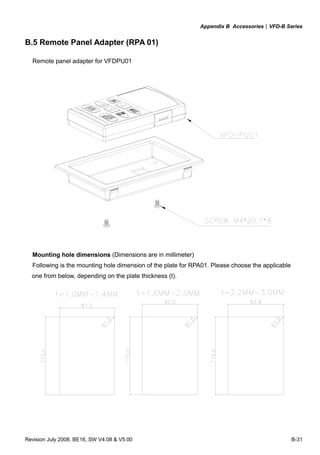

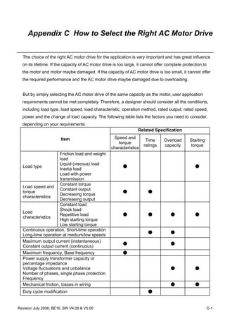
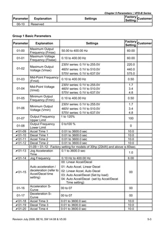
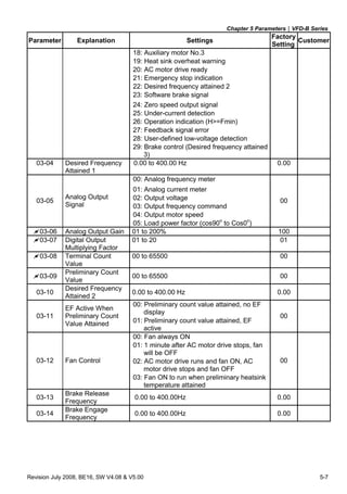
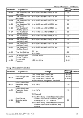
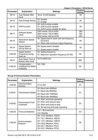
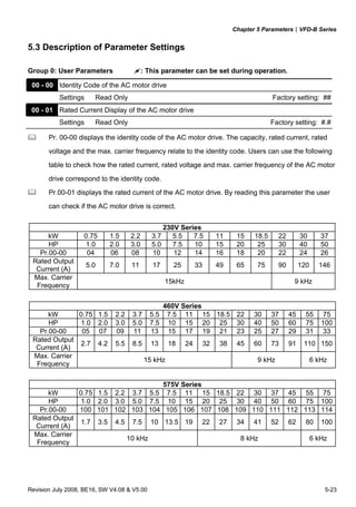
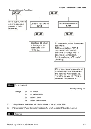
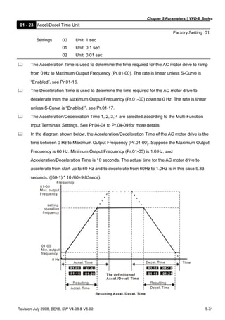
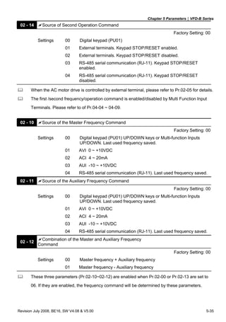
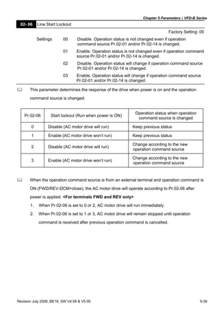
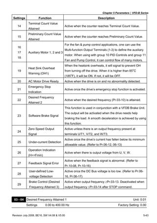
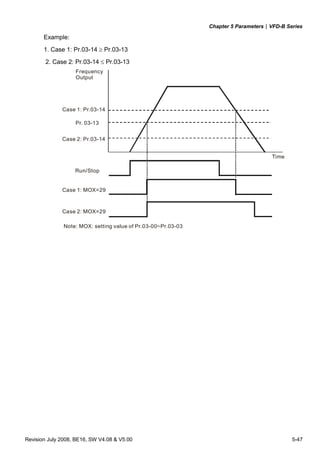
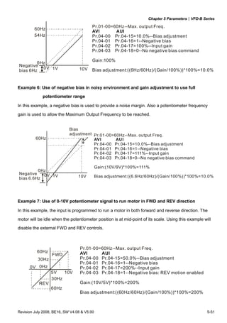
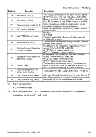
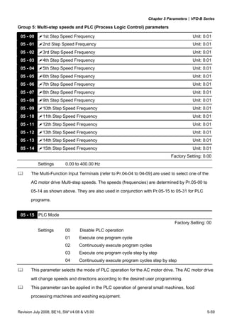
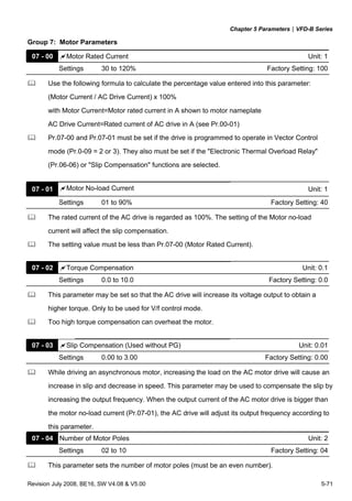
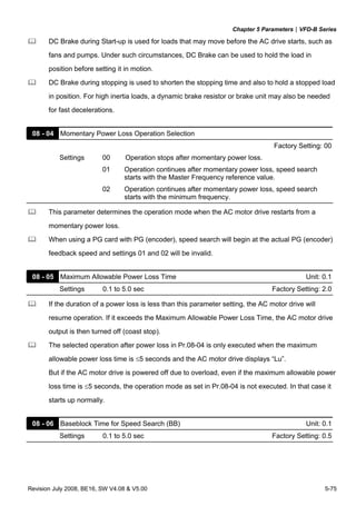
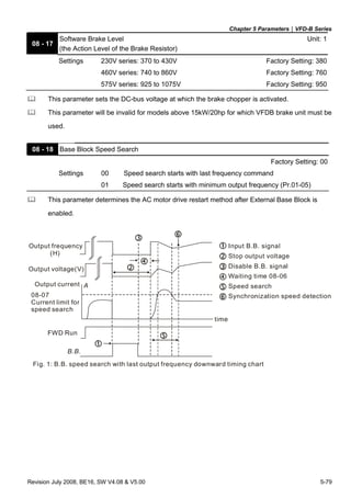
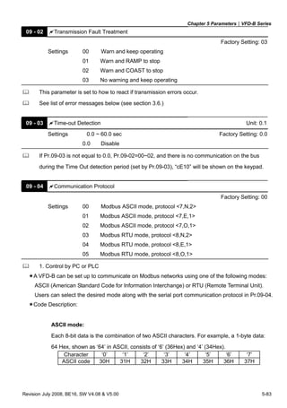
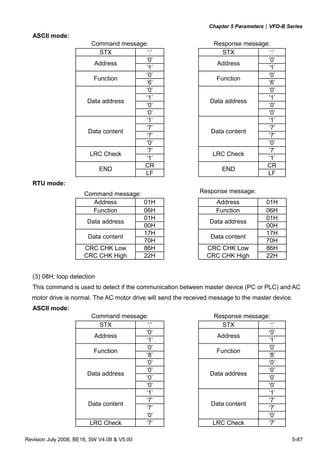
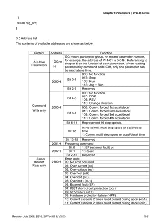
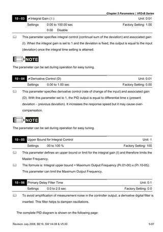
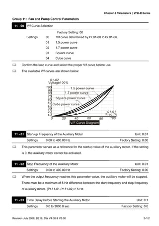
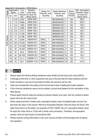
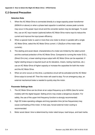
![Appendix C How to Select the Right AC Motor Drive|VFD-B Series
C-2 Revision July 2008, BE16, SW V4.08 & V5.00
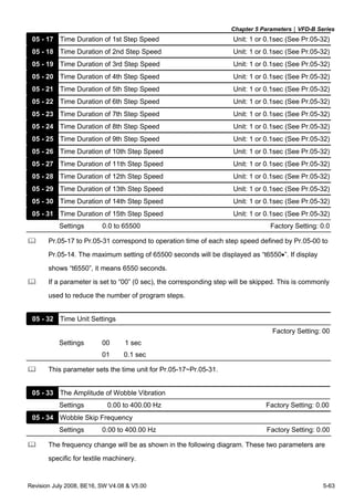
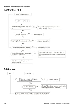
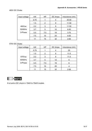
C.1 Capacity Formulas
1. When one AC motor drive operates one motor
The starting capacity should be less than 1.5x rated capacity of AC motor drive
The starting capacity=
)(_____5.1
375cos973
2
kVAdrivemotorACofcapacitythe
t
NGD
T
Nk
A
L ×≤⎟⎟
⎠
⎞
⎜⎜
⎝
⎛
×+
××
×
ϕη
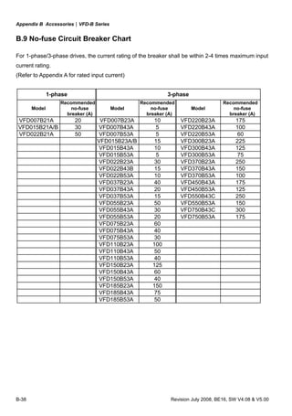
2. When one AC motor drive operates more than one motor
2.1 The starting capacity should be less than the rated capacity of AC motor drive
Acceleration time ≦60 seconds
The starting capacity=
( )[ ] ( ) )(_____5.11
cos
111 kVAdrivemotorACofcapacitythek
n
n
Pknn
Nk
sCss
T
s
T ×≤+=+
×
×
⎥
⎥
⎥
⎦
⎤
⎢
⎢
⎢
⎣
⎡
−−
ϕη
Acceleration time ≧60 seconds
The starting capacity=
( )[ ] ( ) )(_____1
cos
111 kVAdrivemotorACofcapacitythek
n
n
Pknn
Nk
sCss
T
s
T ≤+=+
×
×
⎥
⎥
⎥
⎦
⎤
⎢
⎢
⎢
⎣
⎡
−−
ϕη
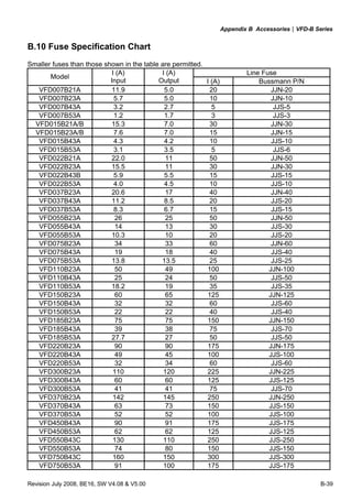
2.2 The current should be less than the rated current of AC motor drive(A)
Acceleration time ≦60 seconds
)(______5.111 AdrivemotorACofcurrentratedthekn
nIn SM
T
S
T ×≤++ ⎥
⎦
⎤
⎢
⎣
⎡
⎟
⎠
⎞⎜
⎝
⎛ −
Acceleration time ≧60 seconds
)(______11 AdrivemotorACofcurrentratedthekn
nIn SM
T
S
T ≤++ ⎥
⎦
⎤
⎢
⎣
⎡
⎟
⎠
⎞⎜
⎝
⎛ −
2.3 When it is running continuously](https://image.slidesharecdn.com/vfd-bmanualen-140613014201-phpapp01/85/Vfd-b-manual-en-233-320.jpg)


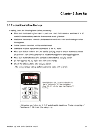
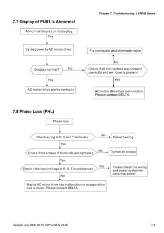
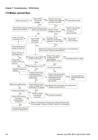
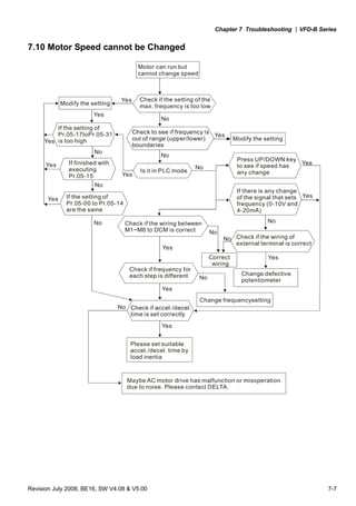
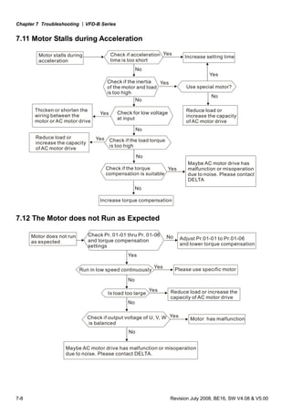
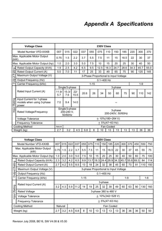
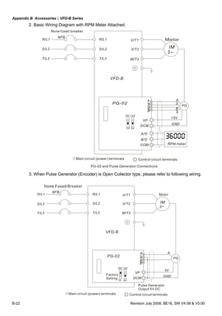
This document provides instructions for installing and operating a DELTA VFD-B Series AC motor drive. It describes receiving the product and inspecting for damage or incorrect parts. Safety guidelines are outlined that must be followed before powering and wiring the drive. Only qualified personnel should install, start-up and maintain the drive. The document provides dimensions and specifications for the drive frames and information on preparing the drive for installation such as removing the keypad and front cover. It also describes proper lifting of larger drives and storage conditions.


![Ct2000 pro plus_manual_english[1]](https://cdn.slidesharecdn.com/ss_thumbnails/ct2000proplusmanualenglish1-140613213527-phpapp02-thumbnail.jpg?width=640&height=640&fit=bounds)


![Ct2000 es manual_english_version_1[1].0](https://cdn.slidesharecdn.com/ss_thumbnails/ct2000esmanualenglishversion11-140613213448-phpapp01-thumbnail.jpg?width=640&height=640&fit=bounds)


