Downloaded 15 times
![Chapter01 Introduction to CP2000
1-5
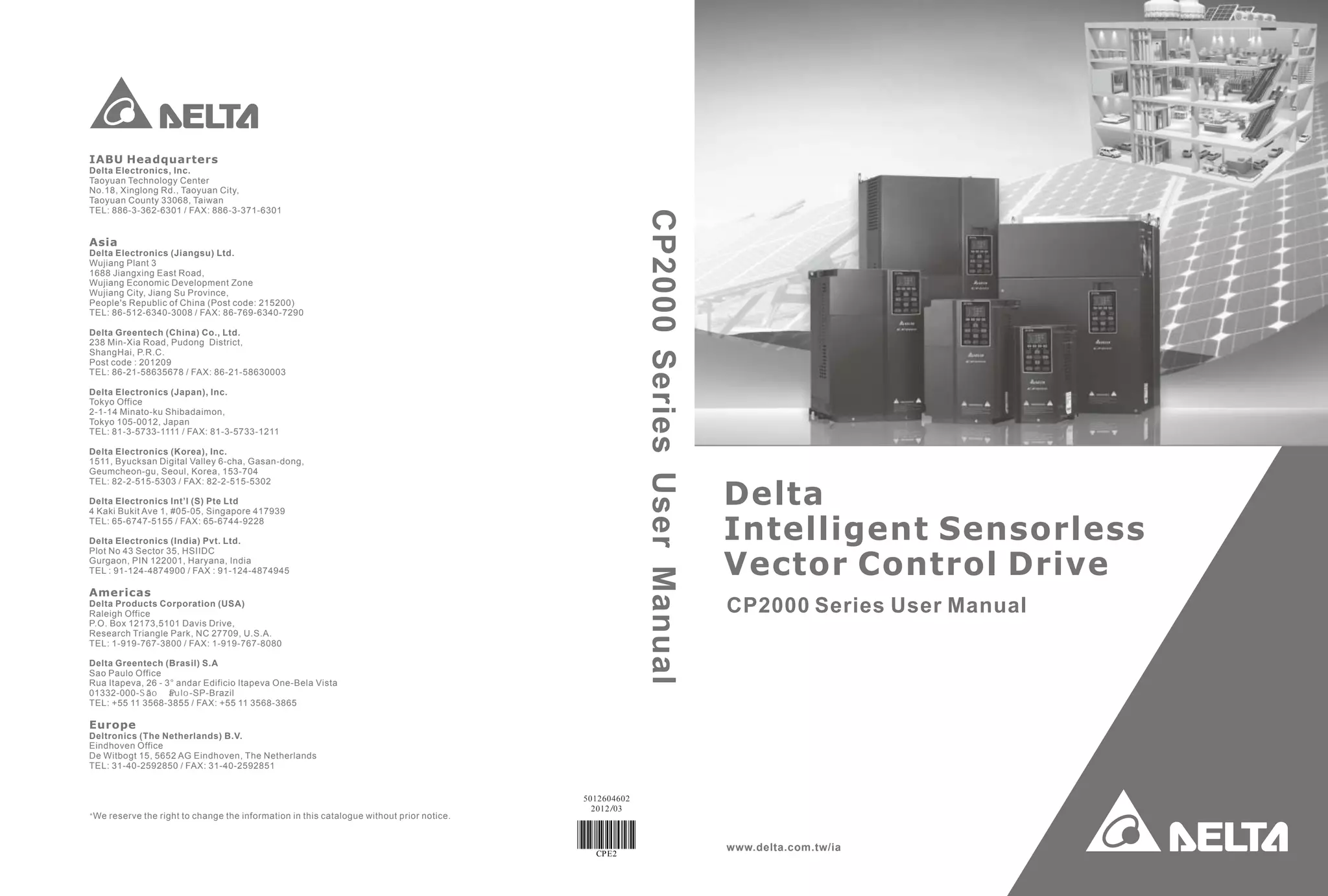
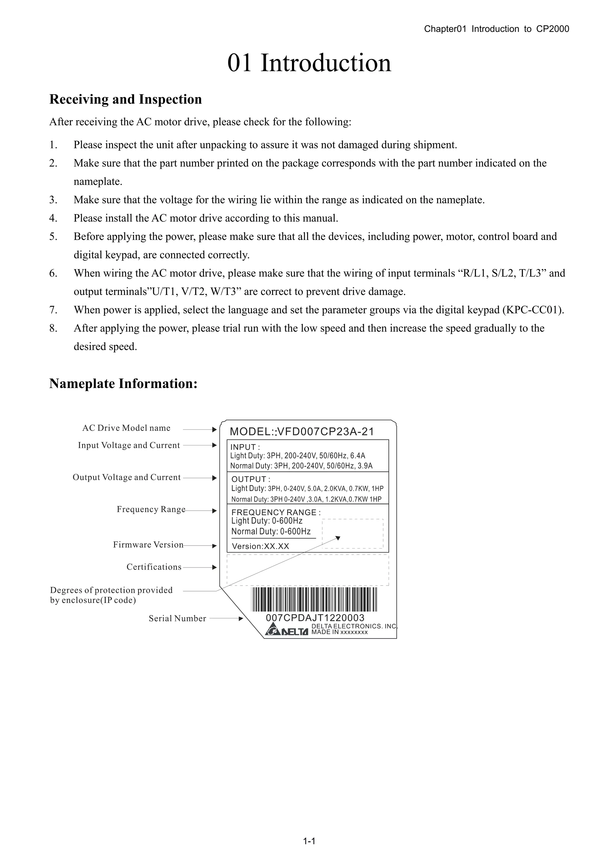
Dimensions:
Frame A, Corresponding models:
VFD007CP23A-21;VFD015CP23A-21,VFD022CP23A-21,VFD037CP23A-21,VFD055CP23A-21,
VFD007CP43A-21, VFD015CP43A-21,VFD022CP43A-21,VFD037CP43A-21,
VFD040CP43A-21,VFD055CP43A-21,VFD075CP43A-21,VFD007CP4EA-21,VFD015CP4EA-21,
VFD022CP4EA-21,VFD037CP4EA-21; VFD040CP4EA-21,VFD055CP4EA-21,VFD075CP4EA-21
Unit:mm [inch]
Frame W H D W1 H1 D1* S1 Φ1 Φ2 Φ3
A1
130.0
[5.12]
250.0
[9.84]
170.0
[6.69]
116.0
[4.57]
236.0
[9.29]
45.8
[1.80]
6.2
[0.24]
22.2
[0.87]
34.0
[1.34]
28.0
[1.10]
D1*:Flange mounting](https://image.slidesharecdn.com/deltacp2000men20120331-140612232906-phpapp02/75/Delta-cp2000-m_en_20120331-9-2048.jpg)
![Chapter01 Introduction to CP2000
1-6
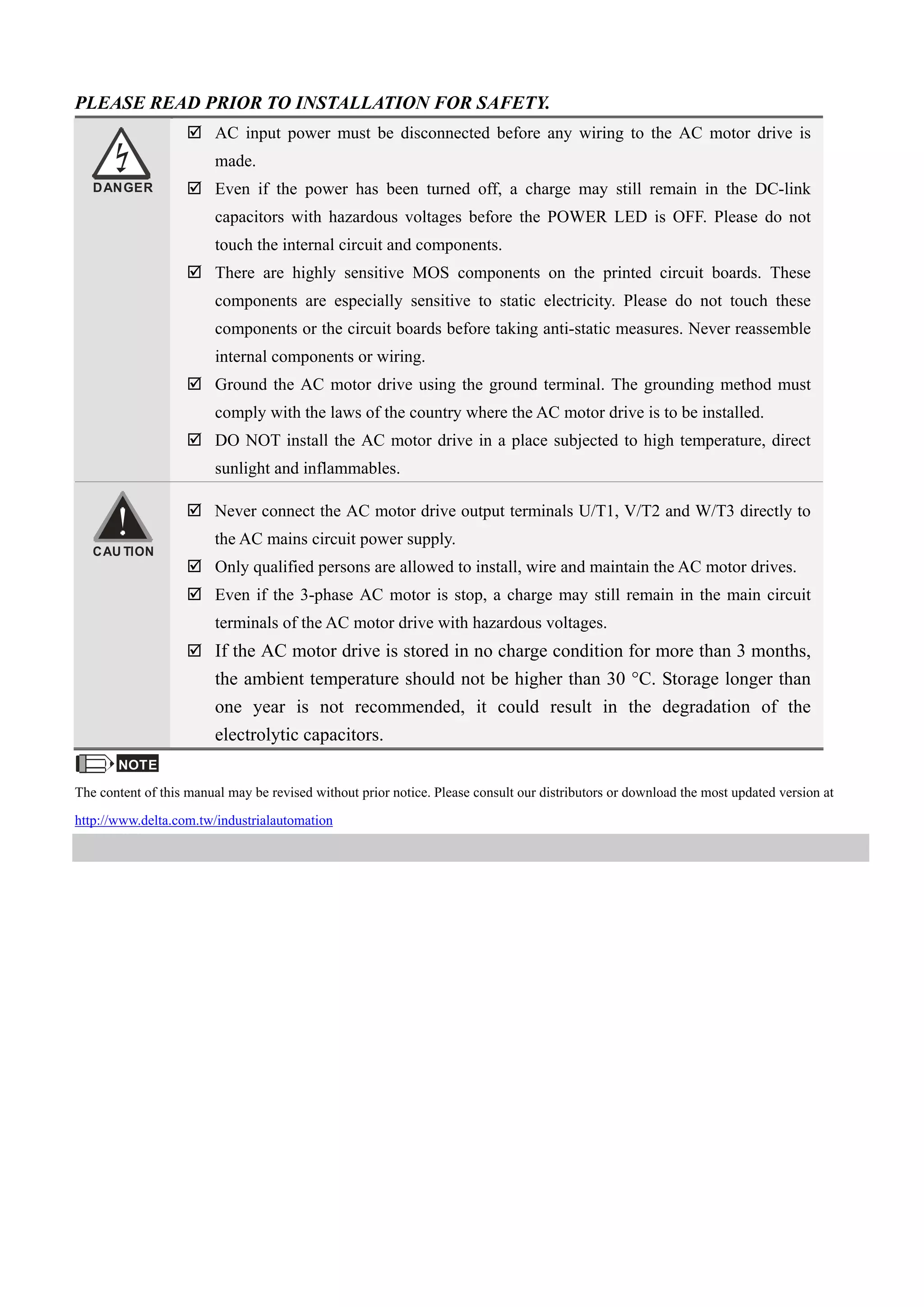
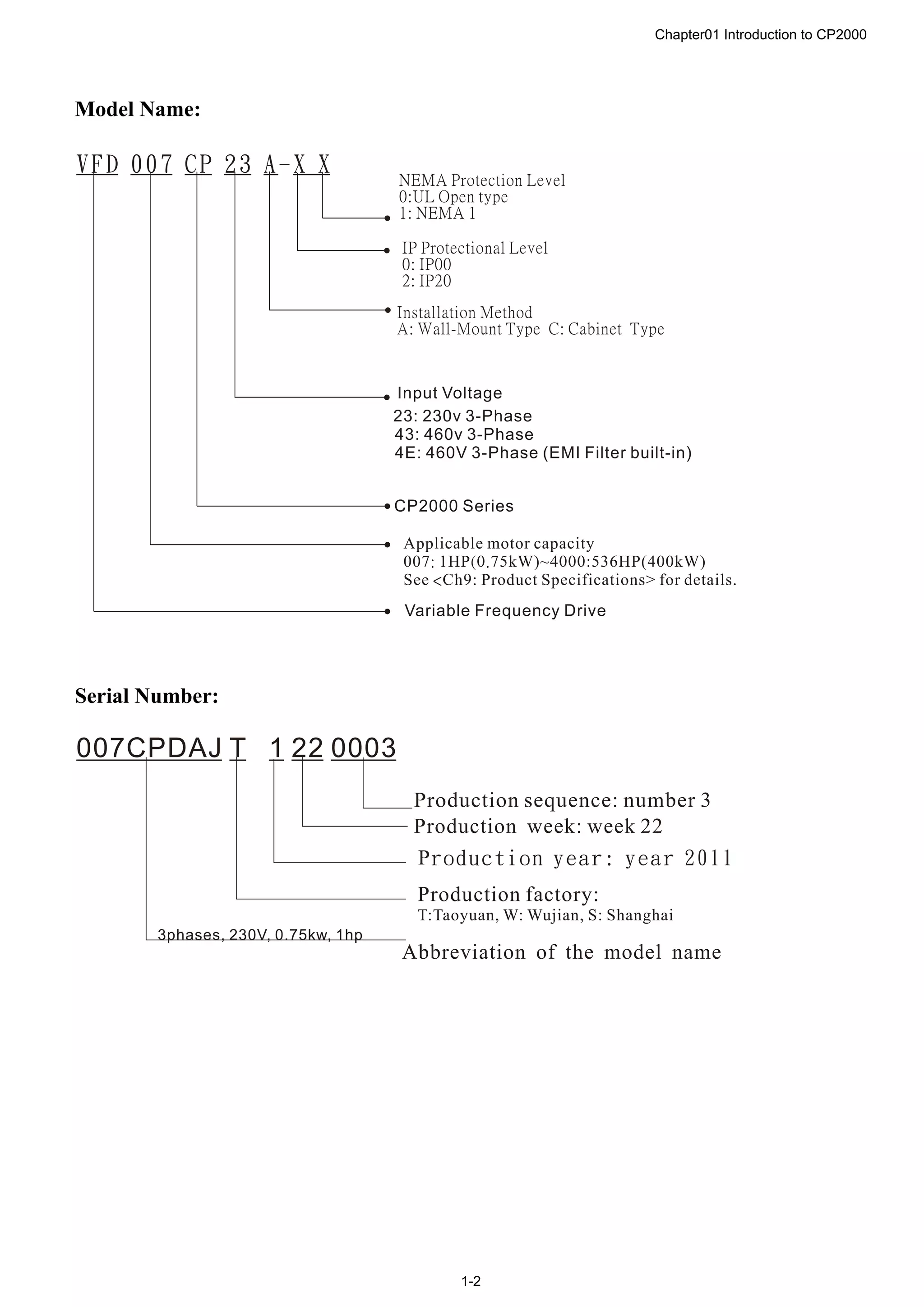
Frame B
Corresponding models:
VFD075CP23A-21,VFD110CP23A-21,VFD150CP23A-21,VFD110CP43A-21,
VFD150CP43A-21,VFD185CP43A-21,VFD110CP4EA-21,VFD150CP4EA-21,
VFD185CP4EA-21
Detail A (Mounting Hole)
Detail B (Mounting Hole)
See Detail A
See Detail B
Unit:mm [inch]
Frame W H D W1 H1 D1* S1 Φ1 Φ2 Φ3
B
190.0
[7.48]
320.0
[12.60]
190.0
[7.48]
173.0
[6.81]
303.0
[11.93]
77.9
[3.07]
8.5
[0.33]
22.2
[0.87]
34.0
[1.34]
43.8
[1.72]
D1*:Flange mounting](https://image.slidesharecdn.com/deltacp2000men20120331-140612232906-phpapp02/75/Delta-cp2000-m_en_20120331-10-2048.jpg)
![Chapter01 Introduction to CP2000
1-7
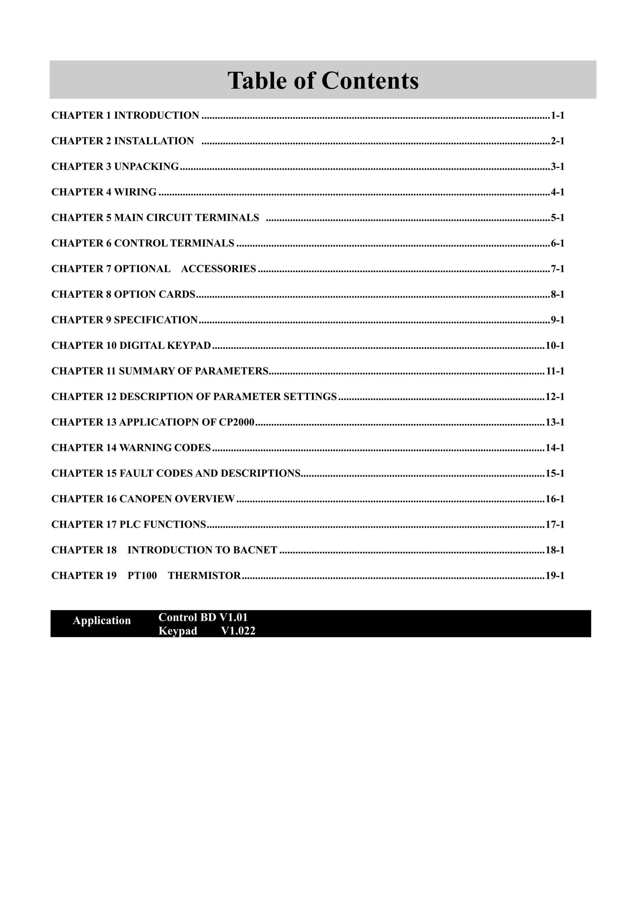
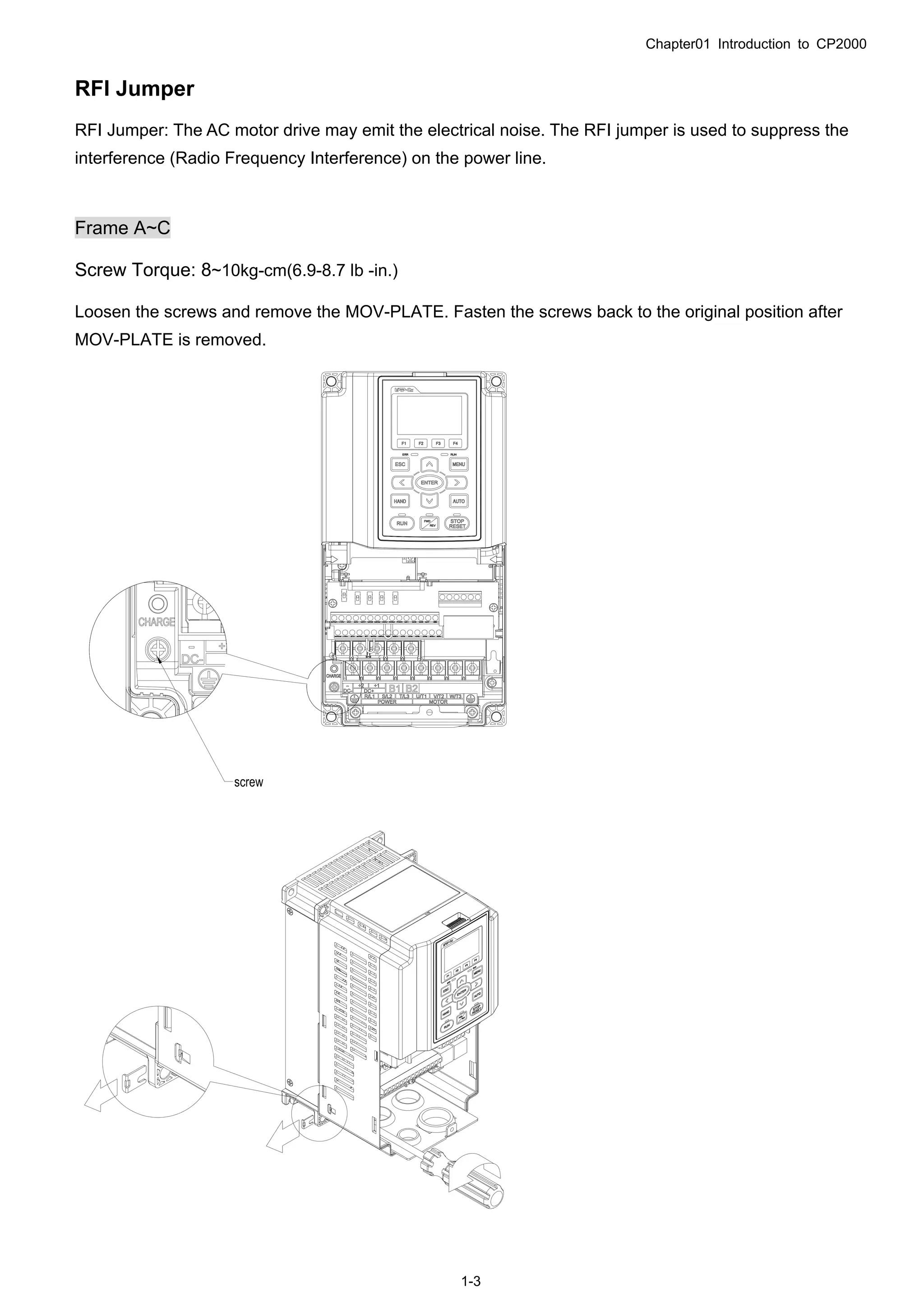
Frame C
Corresponding models:
VFD185CP23A-21,VFD220CP23A-21,VFD300CP23A-21,VFD220CP43A-21,
VFD300CP43A-21,VFD370CP43A-21,VFD220CP4EA-21,VFD300CP4EA-21,
VFD370CP4EA-21
Detail A (Mounting Hole)
Detail B (Mounting Hole)
See Detail A
See Detail B
Unit:mm [inch]
Frame W H D W1 H1 D1* S1 Φ1 Φ2 Φ3
C
250.0
[9.84]
400.0
[15.75]
210.0
[8.27]
231.0
[9.09]
381.0
[15.00]
92.9
[3.66]
8.5
[0.33]
22.2
[0.87]
34.0
[1.34]
50.0
[1.97]
D1*:Flange mounting](https://image.slidesharecdn.com/deltacp2000men20120331-140612232906-phpapp02/75/Delta-cp2000-m_en_20120331-11-2048.jpg)
![Chapter01 Introduction to CP2000
1-9
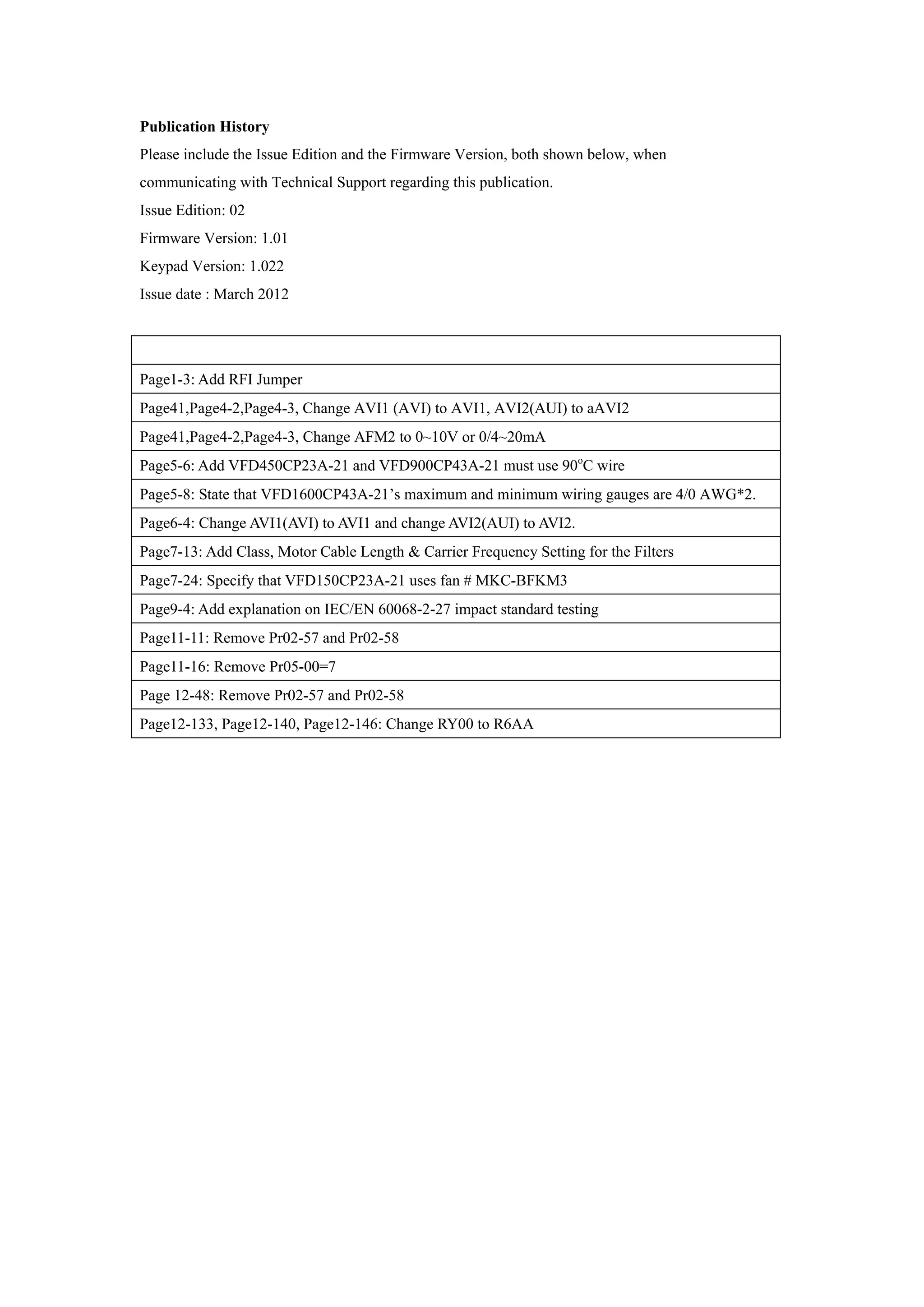
W
W1
1
2
3
H
H1
H2
S1S1
SEE DETAIL A
DETAIL A
(MOUNTING HOLE)
DETAIL B
(MOUNTING HOLE)
SEE DETAIL B
3
2
1
D
H3
D1
S2
D2
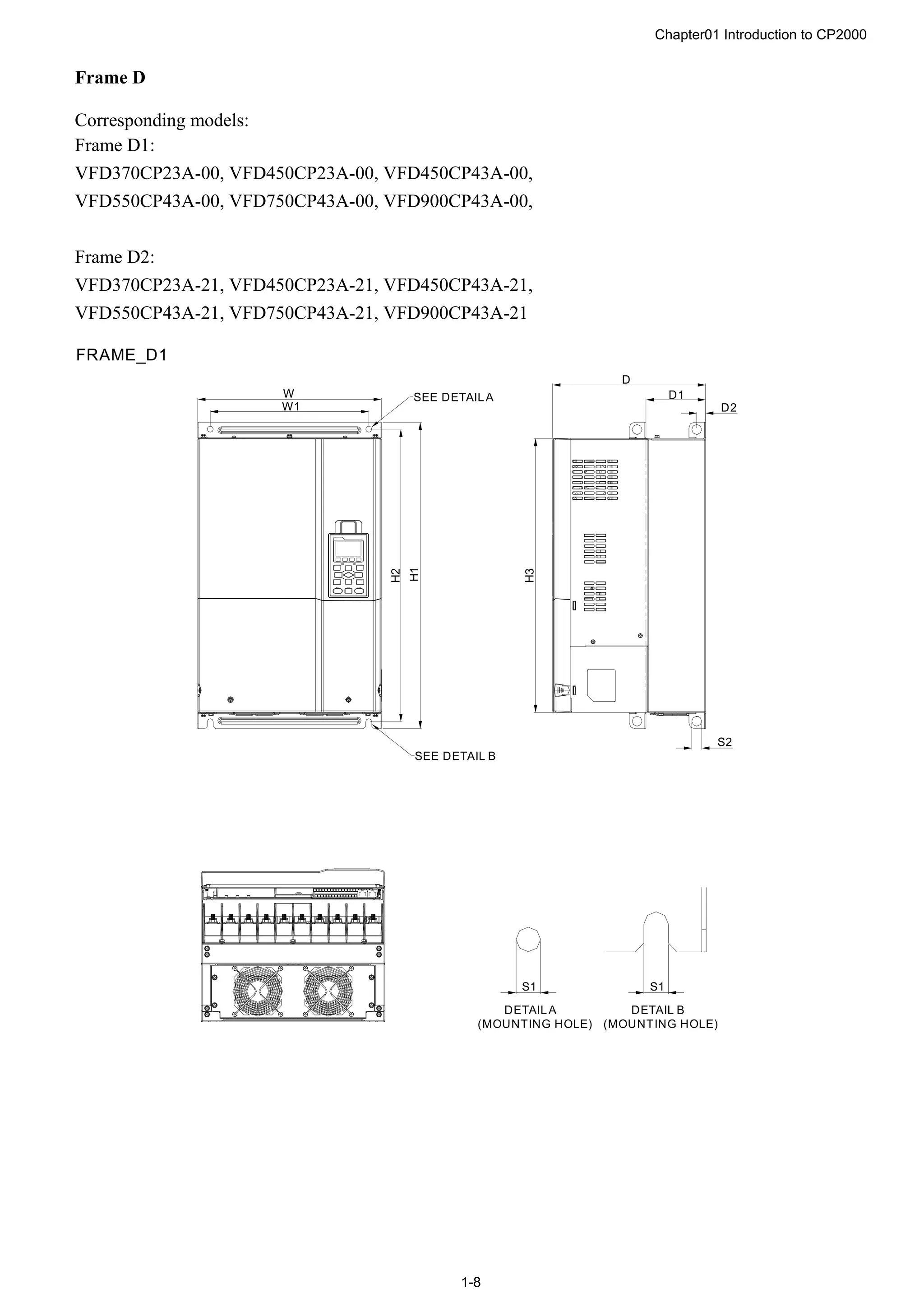
FRAME_D2
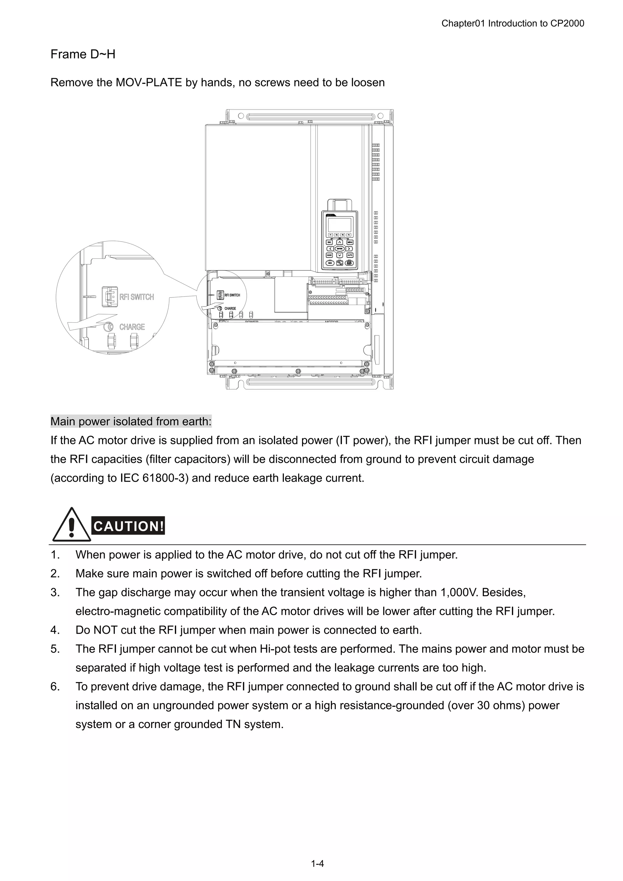
Unit:mm[inch]
Frame W H D W1 H1 H2 H3 D1* D2 S1 S2 Φ1 Φ2 Φ3
D1
330.0
[12.99]
-
275.0
[10.83]
285.0
[11.22]
550.0
[21.65]
525.0
[20.67]
492.0
[19.37]
107.2
[4.22]
16.0
[0.63]
11.0
[0.43]
18.0
[0.71]
- - -
D2
330.0
[12.99]
688.3
[27.10]
275.0
[10.83]
285.0
[11.22]
550.0
[21.65]
525.0
[20.67]
492.0
[19.37]
107.2
[4.22]
16.0
[0.63]
11.0
[0.43]
18.0
[0.71]
76.2
[3.00]
34.0
[1.34]
22.0
[0.87]
D1*:Flange mounting](https://image.slidesharecdn.com/deltacp2000men20120331-140612232906-phpapp02/75/Delta-cp2000-m_en_20120331-13-2048.jpg)
![Chapter01 Introduction to CP2000
1-11
W1
W
H2
H1
H3
H
D1
D
?
?
?
?
?
?
?
?
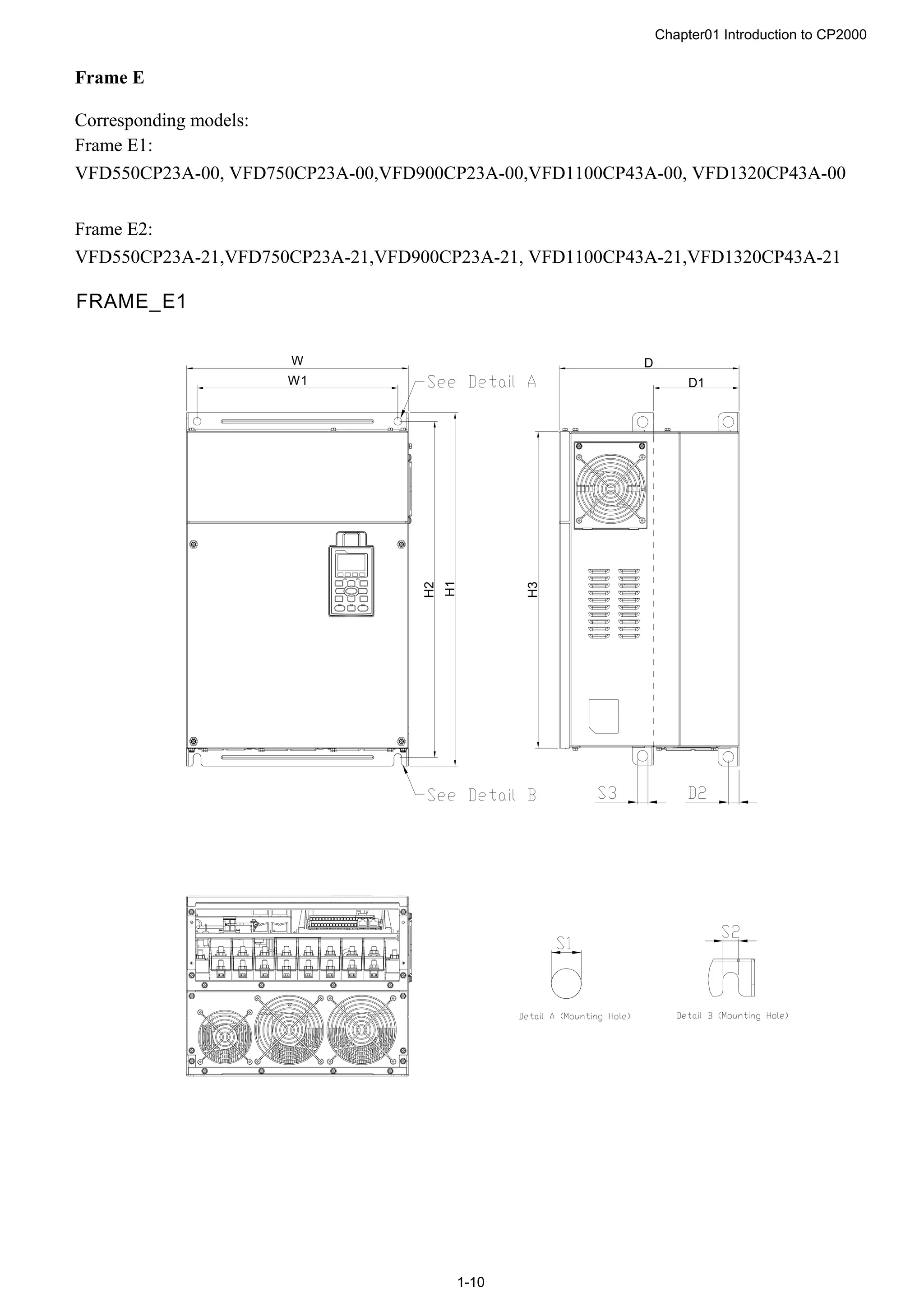
FRAME_E2
Unit:mm [inch]
Frame W H D W1 H1 H2 H3 D1* D2 S1, S2 S3 Φ1 Φ2 Φ3
E1
370.0
[14.57]
-
300.0
[11.81]
335.0
[13.19
589
[23.19]
560.0
[22.05]
528.0
[20.80]
143.0
[5.63]
18.0
[0.71]
13.0
[0.51]
18.0
[0.71]
- - -
E2
370.0
[14.57]
715.8
[28.18]
300.0
[11.81]
335.0
[13.19
589
[23.19]
560.0
[22.05]
528.0
[20.80]
143.0
[5.63]
18.0
[0.71]
13.0
[0.51]
18.0
[0.71]
22.0
[0.87]
34.0
[1.34]
92.0
[3.62]
D1*:Flange mounting](https://image.slidesharecdn.com/deltacp2000men20120331-140612232906-phpapp02/75/Delta-cp2000-m_en_20120331-15-2048.jpg)
![Chapter01 Introduction to CP2000
1-13
H1
H2
S1
S1
D2
W
W1
D
D1
H3
H
S2
S3
3
2
1
2
2
2
3
1
See Detail A
See Detail B
Detail A (Mounting Hole)
Detail B (Mounting Hole)
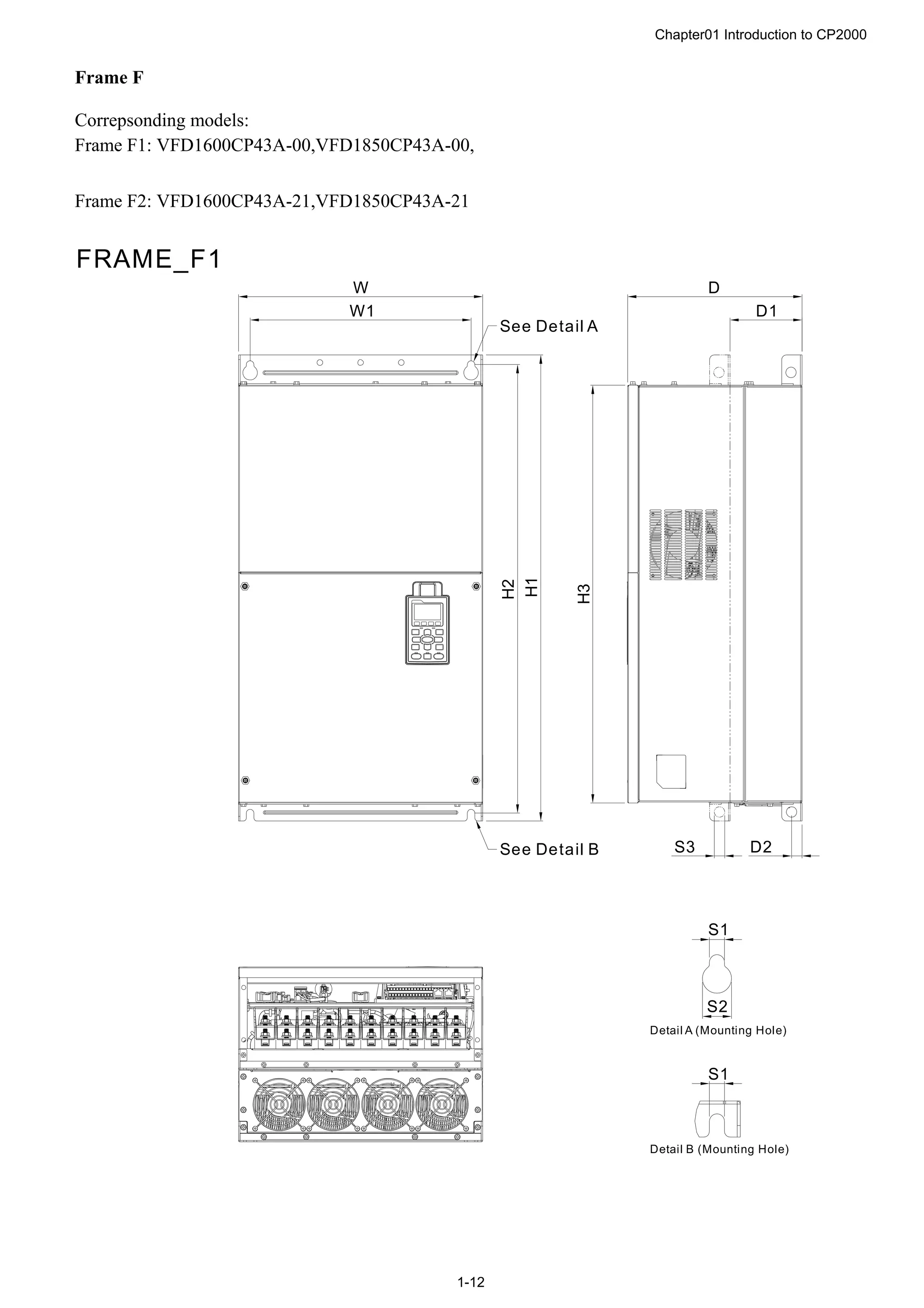
FRAME_F2
Unit:mm [inch]
Frame W H D W1 H1 H2 H3 D1* D2 S1 S2 S3
F1
420.0
[16.54]
-
300.0
[11.81]
380.0
[14.96]
800.0
[31.50]
770.0
[30.32]
717.0
[28.23]
124.0
[4.88]
18.0
[0.71]
13.0
[0.51]
25.0
[0.98]
18.0
[0.71]
F2
420.0
[16.54]
940.0
[37.00]
300.0
[11.81]
380.0
[14.96]
800.0
[31.50]
770.0
[30.32]
717.0
[28.23]
124.0
[4.88]
18.0
[0.71]
13.0
[0.51]
25.0
[0.98]
18.0
[0.71]
Frame Φ1 Φ2 Φ3
F1 - - -
F2 92.0
[3.62]
35.0
[1.38]
22.0
[0.87]
D1*:Flange mounting](https://image.slidesharecdn.com/deltacp2000men20120331-140612232906-phpapp02/75/Delta-cp2000-m_en_20120331-17-2048.jpg)
![Chapter01 Introduction to CP2000
1-15
W1
W
H2
H1
H
H3
D
S 3
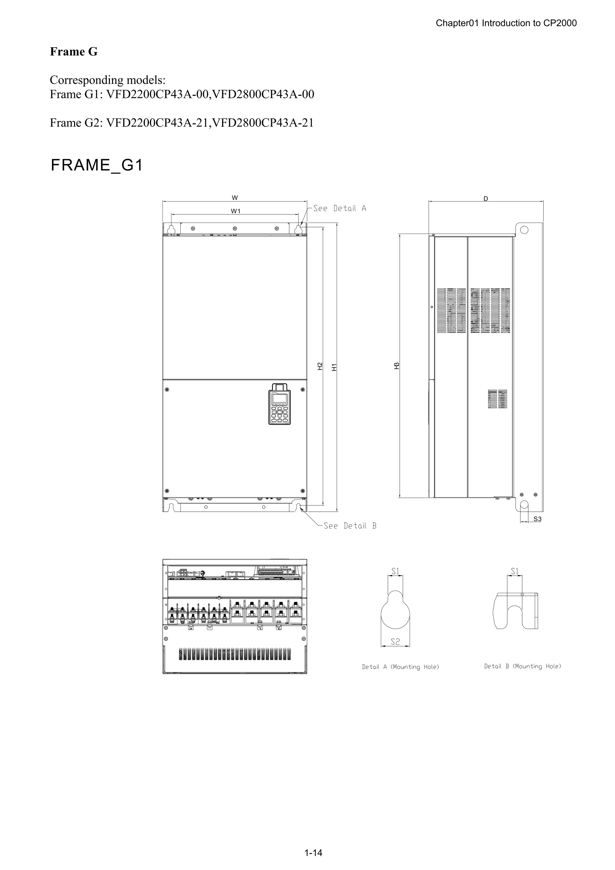
FRAME_G2
Unit:mm [inch]
Frame W H D W1 H1 H2 H3 S1 S2 S3 Φ1 Φ2 Φ3
G1
500.0
[19.69]
-
397.0
[15.63]
440.0
[217.32]
1000.0
[39.37]
963.0
[37.91]
913.6
[35.97]
13.0
[0.51]
26.5
[1.04]
27.0
[1.06]
- - -
G2
500.0
[19.69]
1240.2
[48.83]
397.0
[15.63]
440.0
[217.32]
1000.0
[39.37]
963.0
[37.91]
913.6
[35.97]
13.0
[0.51]
26.5
[1.04]
27.0
[1.06]
22.0
[0.87]
34.0
[1.34]
117.5
[4.63]](https://image.slidesharecdn.com/deltacp2000men20120331-140612232906-phpapp02/75/Delta-cp2000-m_en_20120331-19-2048.jpg)
![Chapter01 Introduction to CP2000
1-18
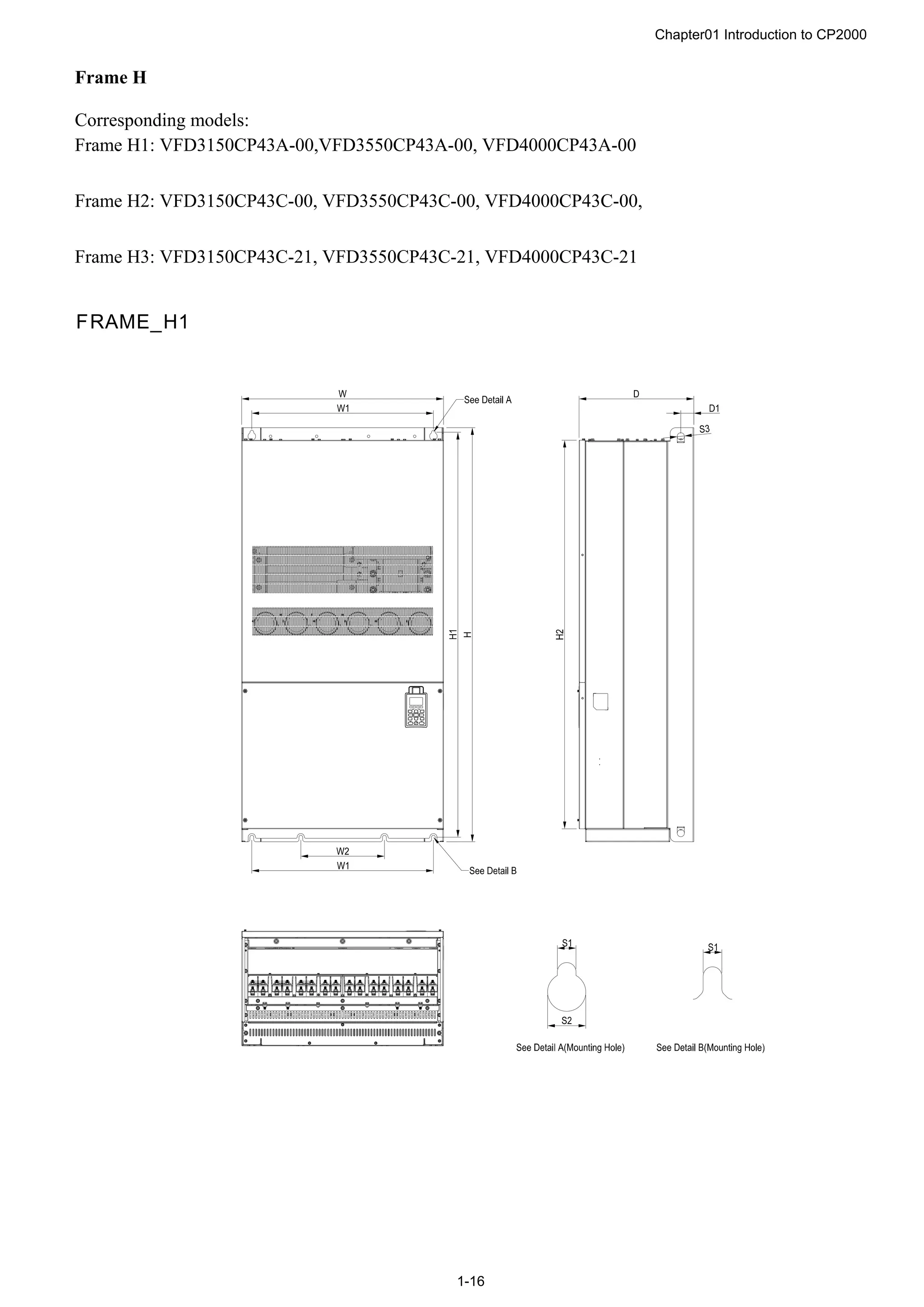
FRAME_H3
Unit:mm [inch]
Frame W H D W1 W2 W3 W4 W5 W6 H1 H2 H3 H4
H1
700.0
[27.56]
1435.0
[56.5]
398.0
[15.67]
630.0
[24.8]
290.0
[11.42]
- - - -
1403.0
[55.24]
1346.6
[53.02]
- -
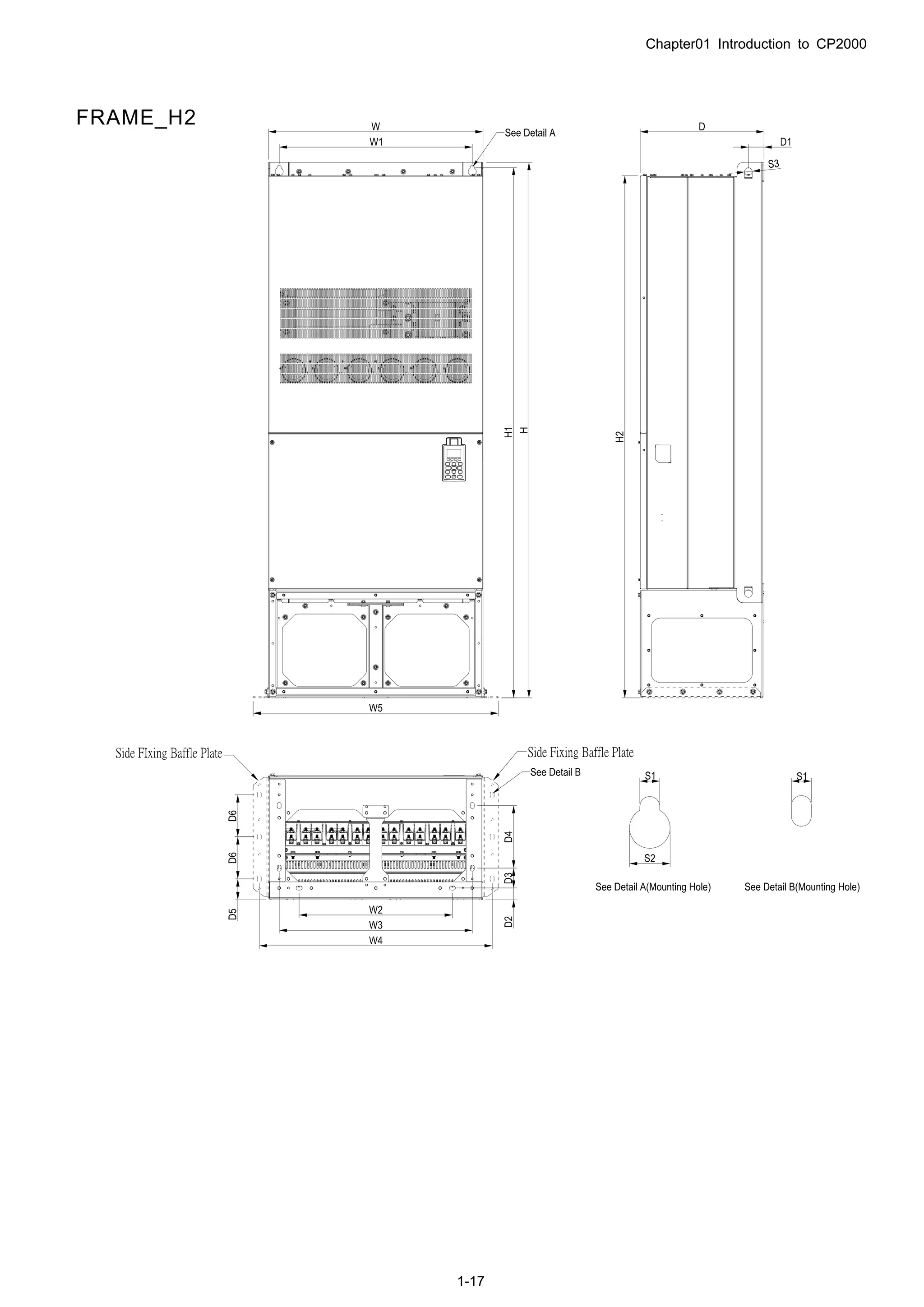
H2
700.0
[27.56]
1745.0
[68.70]
404.0
[15.90]
630.0
[24.8]
500.0
[19.69]-
630.0
[24.80]
760.0
[29.92]
800.0
[31.5]
-
1729.0
[68.07]
1701.6
[66.99]
- -
H3
700.0
[27.56]
1745.0
[68.70]
404.0
[15.91]
630.0
[24.80]
500.0
[19.69]
630.0
[24.80]
760.0
[29.92]
800.0
[31.5]
-
1729.0
[68.07]
1701.6
[66.99]
- -
Frame H5 D1 D2 D3 D4 D5 D6 S1 S2 S3 Φ1 Φ2 Φ3
H1
45.0
[1.77]
- - - - -
13.0
[0.51]
26.5
[1.04]
25.0
[0.98]
- - -
H2
51.0
[2.00]
38.0
[1.50]
65.0
[2.56]
204.0
[8.03]
68.0
[2.68]
137.0
[5.40]
13.0
[0.51]
26.5
[1.04]
25.0
[0.98]
- - -
H3
51.0
[2.00]
38.0
[1.50]
65.0
[2.56]
204.0
[8.03]
68.0
[2.68]
137.0
[5.40]
13.0
[0.51]
26.5
[1.04]
25.0
[0.98]
22.0
[0.87]
34.0
[1.34]
117.5
[4.63]](https://image.slidesharecdn.com/deltacp2000men20120331-140612232906-phpapp02/75/Delta-cp2000-m_en_20120331-22-2048.jpg)
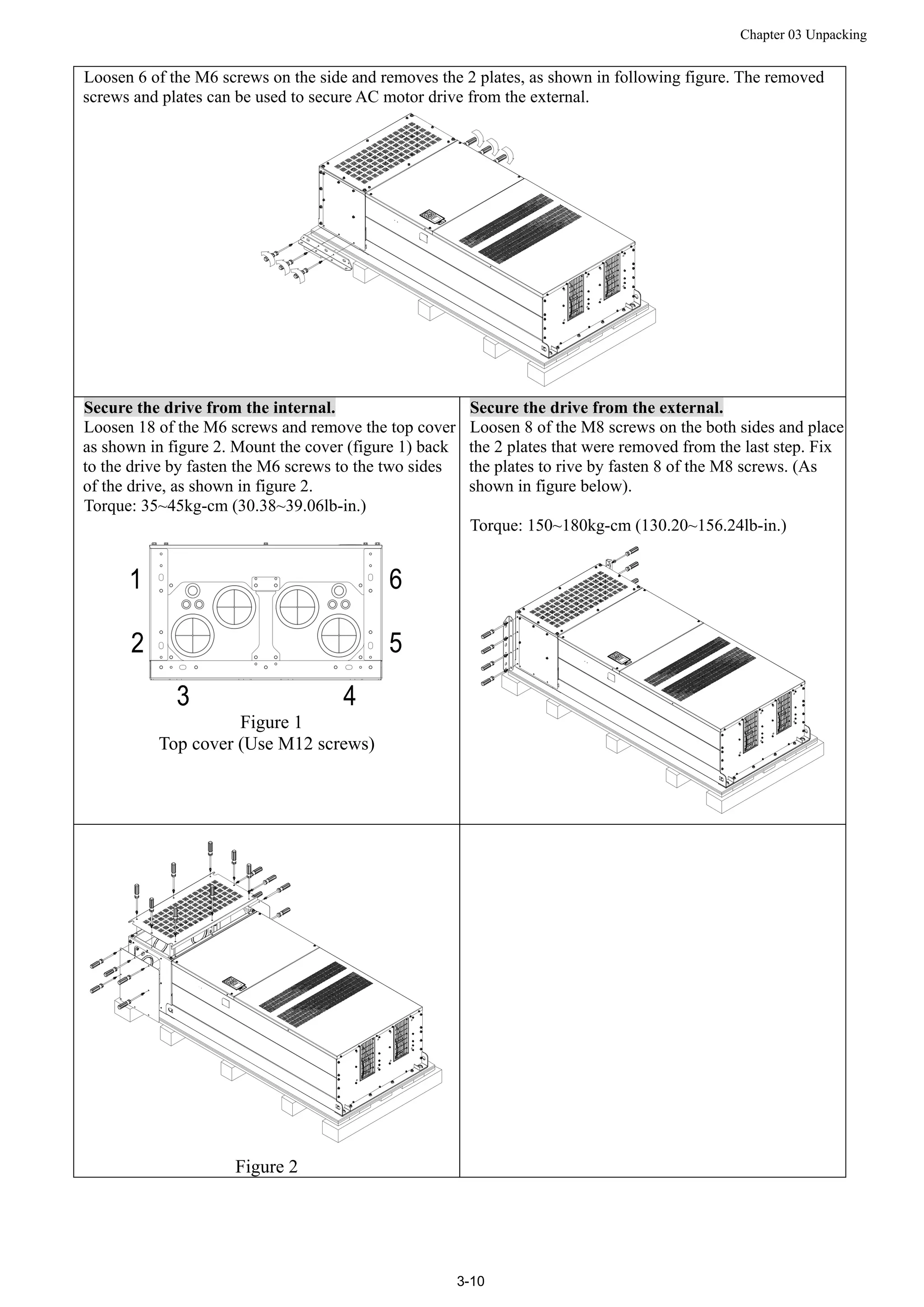
![Chapter 03 Unpacking
3-11
Fasten 6 of the M6 screws that were removed from last step back to the AC motor drive. As shown in figure
below:
Lift the drive by hooking the lifting hole. It is now ready for installation.
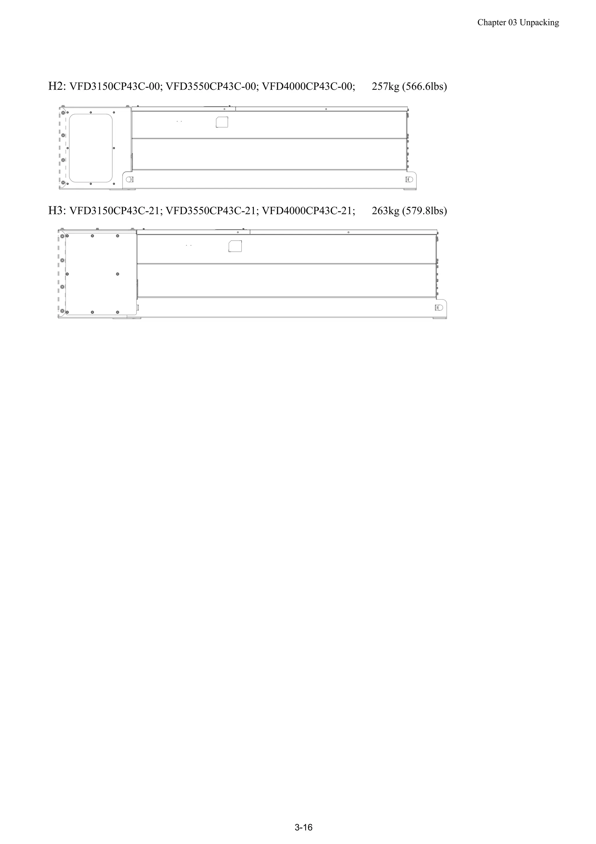
Frame H: Secure the drive
(VFDXXXXCPXXA-00) Screw: M12*6; Torque: 340-420kg-cm [295.1-364.6lb-in.]](https://image.slidesharecdn.com/deltacp2000men20120331-140612232906-phpapp02/75/Delta-cp2000-m_en_20120331-38-2048.jpg)
![Chapter 03 Unpacking
3-12
VFDXXXXCPXXC-00
Secure the drive from internal.
Screw: M12*8
Torque: 340-420kg-cm [295.1-364.6lb-in.]
VFDXXXXCPXXC-21
Secure the drive from the external.
Screw: M12*8
Torque: 340-420kg-cm [295.1-364.6lb-in.]](https://image.slidesharecdn.com/deltacp2000men20120331-140612232906-phpapp02/75/Delta-cp2000-m_en_20120331-39-2048.jpg)
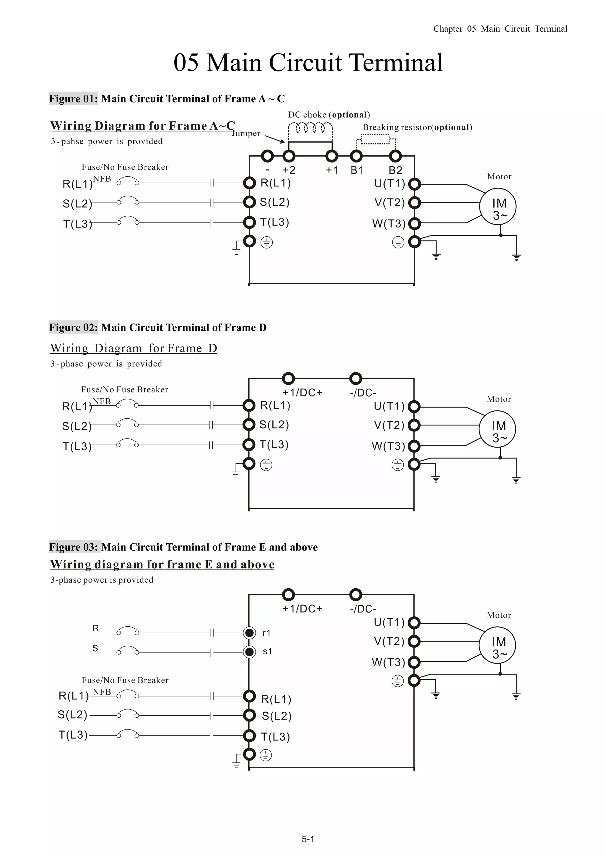
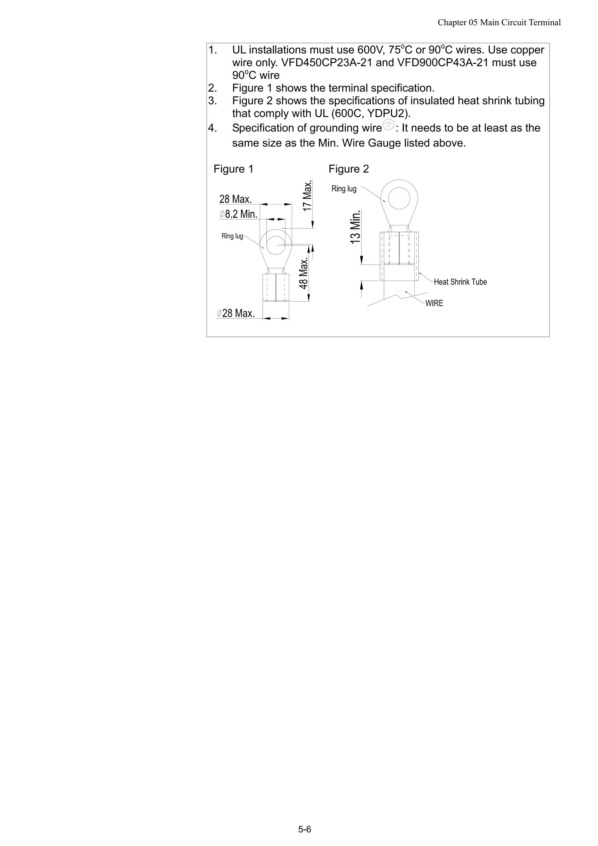
![Chapter 05 Main Circuit Terminal
5-3
R-C (Resistance-Capacitance), unless approved by Delta.
DO NOT connect phase-compensation capacitors or surge absorbers at
the output terminals of AC motor drives.
Use well-insulated motor, suitable for inverter operation.
Terminals for connecting DC reactor, external brake resistor, external
brake resistor and DC circuit
This is the terminals used to connect the DC reactor to improve the
power factor. For the factory setting, it connects the short-circuit object.
Please remove this short-circuit object before connecting to the DC
reactor.
+1 +2
DC reactor (optional)
Connect a brake resistor or brake unit in applications with frequent
deceleration ramps, short deceleration time, too low brake torque or
requiring increased brake torque.
B1 B2
BR
+ -
VFDB
Brake resistor
(optional)
Brake resistor
(optional)
Brake unit
(optional)
The external brake resistor should connect to the terminals (B1, B2) of
AC motor drives.
For those models without built-in brake resistor, please connect external
brake unit and brake resistor (both of them are optional) to increase
brake torque.
When the terminals +1, +2 and - are not used, please leave the terminals
open.
DO NOT connect [+1, -], [+2, -], [+1/DC+, -/DC-] or brake resistor directly
to prevent drive damage.](https://image.slidesharecdn.com/deltacp2000men20120331-140612232906-phpapp02/75/Delta-cp2000-m_en_20120331-51-2048.jpg)
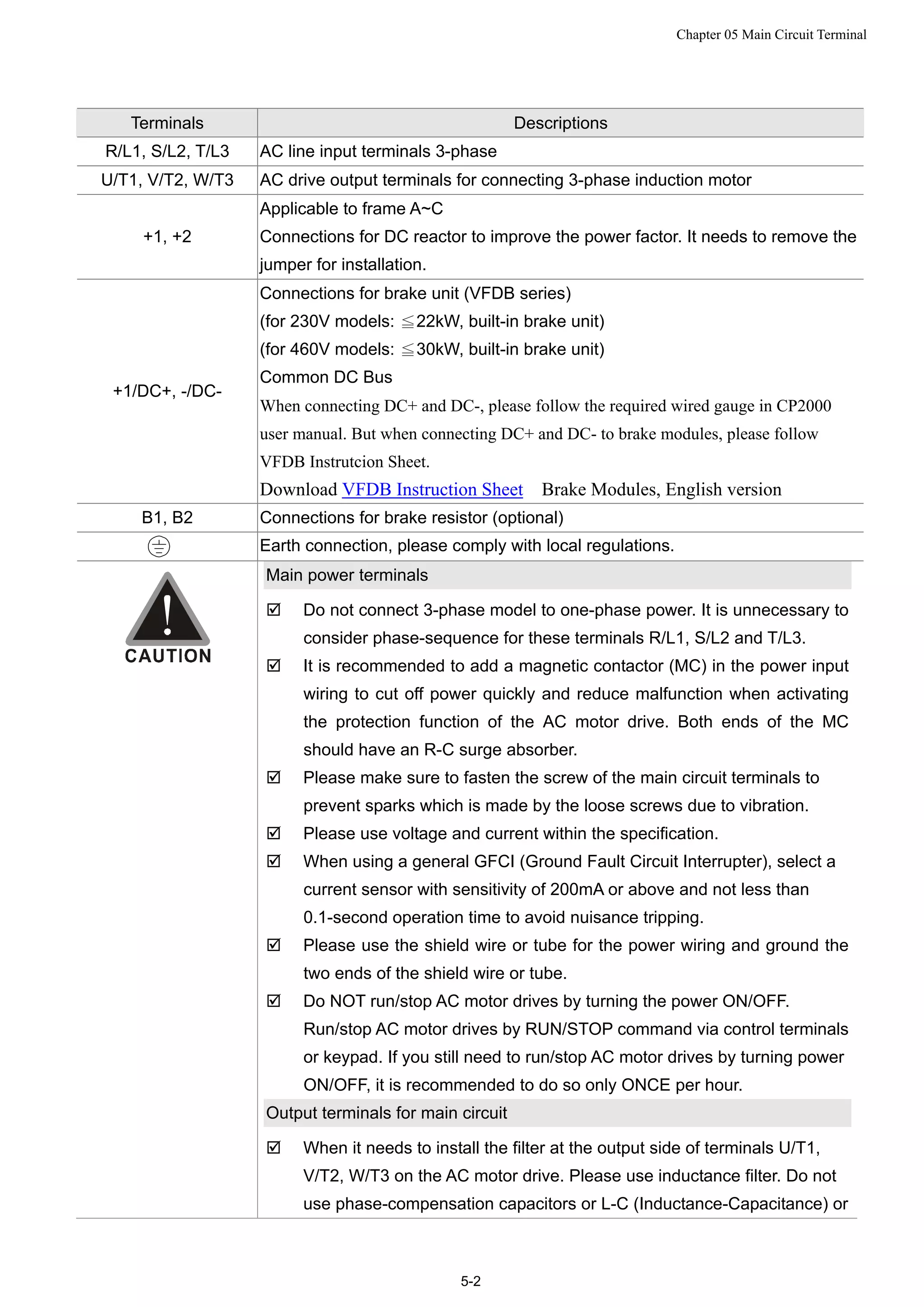
![Chapter 05 Main Circuit Terminal
5-4
Specifications of the Main Circuit Terminals
Frame A Main Circuit Terminals::
R/L1, S/L2, T/L3, U/T1, V/T2, W/T3, , B1, B2, +1, +2,-
Model Max. Wire
Gauge
Min. Wire Gauge Torque(±10%)
VFD007CP23A-21 14 AWG (2.1mm2
)
VFD015CP23A-21 14 AWG (2.1mm2
)
VFD022CP23A-21 14 AWG (2.1mm2
)
VFD037CP23A-21 10 AWG (5.3mm2
)
VFD055CP23A-21 10 AWG (5.3mm2
)
VFD007CP43A-21 14 AWG (2.1mm2
)
VFD015CP43A-21 14 AWG (2.1mm2
)
VFD022CP43A-21 14 AWG (2.1mm2
)
VFD037CP43A-21 14 AWG (2.1mm2
)
VFD040CP43A-21 14 AWG (2.1mm2
)
VFD055CP43A-21 12 AWG (3.3mm2
)
VFD075CP43A-21 12 AWG (3.3mm2
)
VFD007CP4EA-21 14 AWG (2.1mm2
)
VFD015CP4EA-21 14 AWG (2.1mm2
)
VFD022CP4EA-21 14 AWG (2.1mm2
)
VFD037CP4EA-21 14 AWG (2.1mm2
)
VFD040CP4EA-21 12 AWG (3.3mm2
)
VFD055CP4EA-21 10 AWG (5.3mm2
)
VFD075CP4EA-21
8 AWG
(8.4mm2
)
10 AWG (5.3mm2
)
M4
20kg-cm
(17.4 lb-in.)
(1.96Nm)
UL installations must use 600V, 75℃ or 90℃ wire. Use copper wire
only.
Frame B Main Circuit Terminals:
R/L1, S/L2, T/L3, U/T1, V/T2, W/T3, , B1, B2, +1, +2,-
Model Max. Wire
Gauge
Min. Wire Gauge Torque(±10%)
VFD075CP23A-21 8 AWG (8.4mm2
)
VFD110CP23A-21 6 AWG (13.3mm2
)
VFD150CP23A-21 4 AWG (21.2mm2
)
VFD110CP43A-21 8 AWG (8.4mm2
)
VFD150CP43A-21 8 AWG (8.4mm2
)
VFD185CP43A-21 6 AWG (13.3mm2
)
VFD110CP4EA-21 8 AWG (8.4mm2
)
VFD150CP4EA-21 8 AWG (8.4mm2
)
VFD185CP4EA-21
4 AWG
(21.2mm2
)
6 AWG (13.3mm2
)
M5
35kg-cm
(30.4 lb-in.)
(3.434Nm)
UL installations must use 600V, 75℃ or 90℃ wire. Use copper wire
only.
NOTE
Terminal D+ [+2 & +1]: Torque: 45 kg-cm [39.0lb-in.] (4.415Nm) (±10%)
VFD150CP23A-21 must use 600V, 90 wire when surrounding t℃ emperature exceeds
45℃.](https://image.slidesharecdn.com/deltacp2000men20120331-140612232906-phpapp02/75/Delta-cp2000-m_en_20120331-52-2048.jpg)
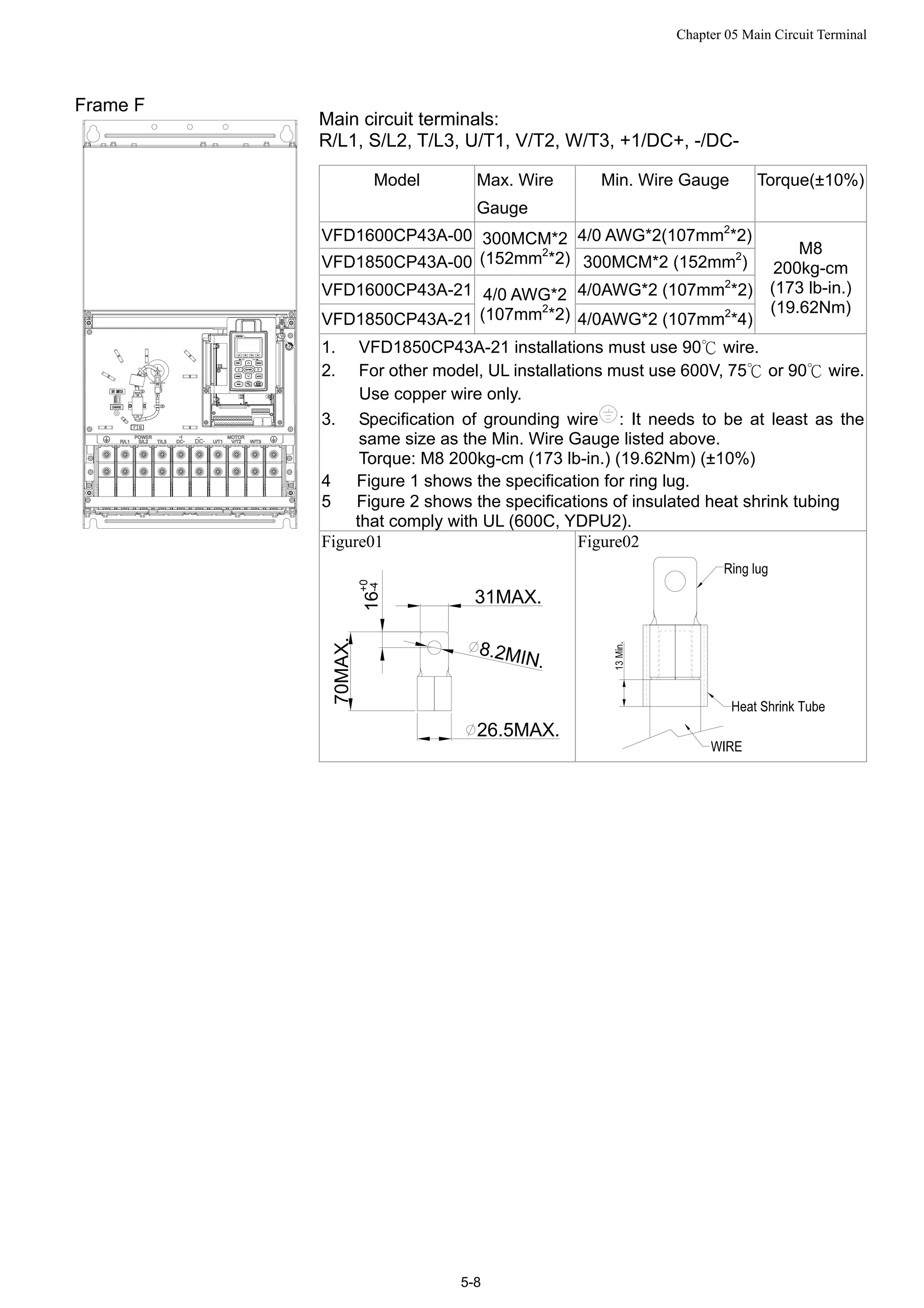
![Chapter 05 Main Circuit Terminal
5-5
Frame C Main circuit terminals:
R/L1, S/L2, T/L3, U/T1, V/T2, W/T3, , B1, B2, +1, +2,-
Model Max. Wire
Gauge
Min. Wire Gauge Torque(±10%)
VFD185CP23A -21 1 AWG (42.4mm2
)
VFD220CP23A-21 1/0 AWG (53.5mm2
)
VFD300CP23A-21 1/0 AWG (53.5mm2
)
VFD220CP43A-21 4 AWG (21.2mm2
)
VFD300CP43A-21 3 AWG (26.7mm2
)
VFD370CP43A-21 2 AWG (33.6mm2
)
VFD220CP4EA-21 4 AWG (21.2mm2
)
VFD300CP4EA-21 3 AWG (26.7mm2
)
VFD370CP4EA-21
1/0 AWG
(53.5mm2
)
2 AWG (33.6mm2
)
M8
80kg-cm
(69.4 lb-in.)
(7.85Nm)
UL installations must use 600V, 75℃ or 90℃ wire. Use copper wire
only.
NOTE
Terminal D+ [+2 & +1]: Torque: 90 kg-cm [78.2lb-in.] (8.83Nm) (±10%)
VFD300CP23A-21 must use 600V, 90 wire when surrounding temperature exceeds℃
45℃
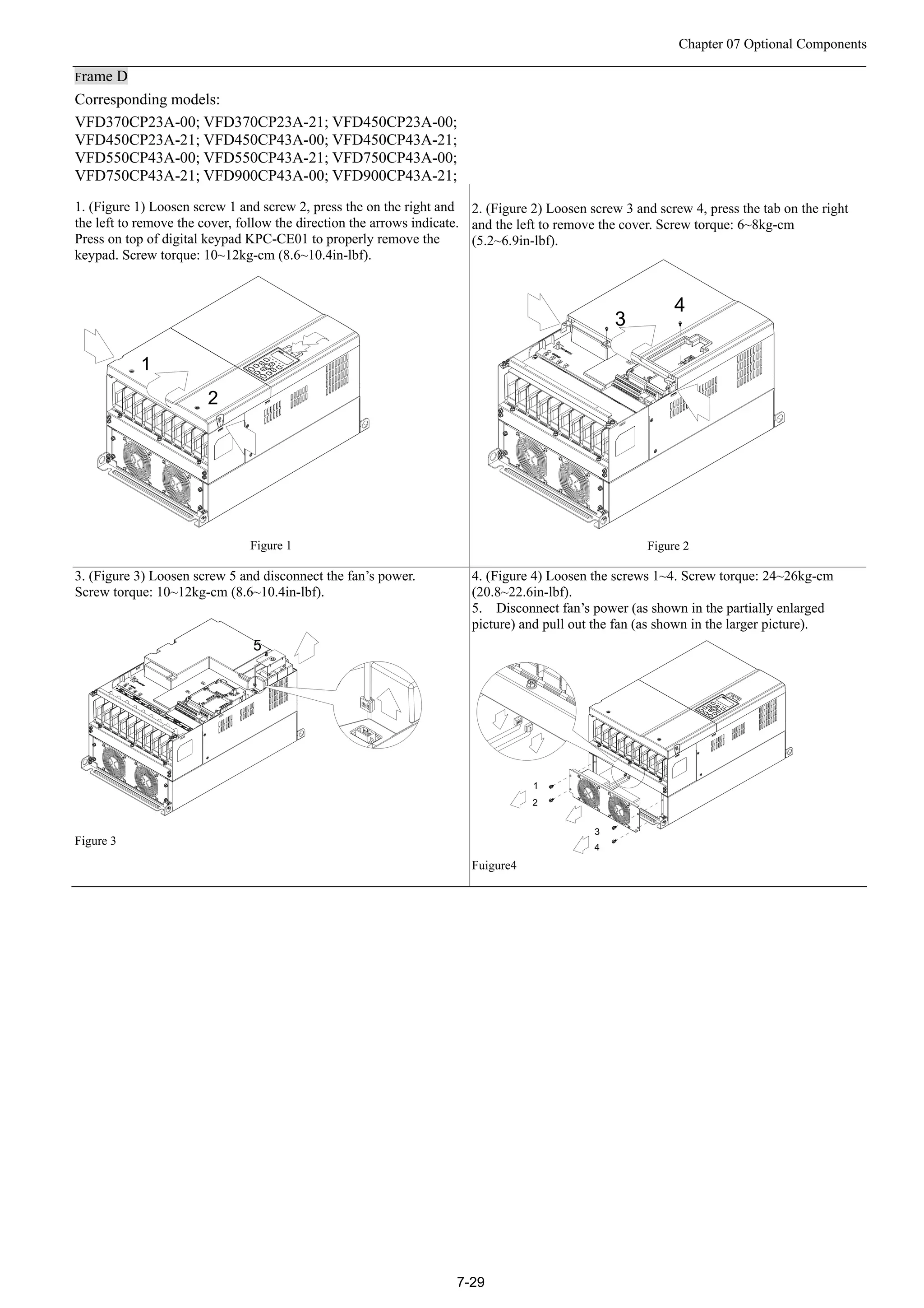
Frame D Main Circuit Terminals:
R/L1, S/L2, T/L3, U/T1, V/T2, W/T3, , +1/DC+, -/DC-
Model Max. Wire
Gauge
Min. Wire Gauge Torque(±10%)
VFD370CP23A-00 4/0 AWG (107mm2
)
VFD450CP23A-00 300MCM(152mm2
)
VFD450CP43A-00 1/0 AWG (53.5mm2
)
VFD550CP43A-00 2/0 AWG (67.4mm2
)
VFD750CP43A-00 3/0AWG (85mm2
)
VFD900CP43A-00
300MCM
(152 mm2
)
300MCM(152mm2
)
VFD370CP23A-21 4/0AWG(107mm2
)
VFD450CP23A-21 4/0 AWG (107mm2
)
VFD450CP43A-21 1/0 AWG (53.5mm2
)
VFD550CP43A-21 2/0 AWG (67.4mm2
)
VFD750CP43A-21 3/0 AWG (85mm2
)
VFD900CP43A-21
4/0 AWG
(107mm2
)
4/0 AWG (107mm2
)
M8
80kg-cm
(173 lb-in.)
(19.62Nm)](https://image.slidesharecdn.com/deltacp2000men20120331-140612232906-phpapp02/75/Delta-cp2000-m_en_20120331-53-2048.jpg)
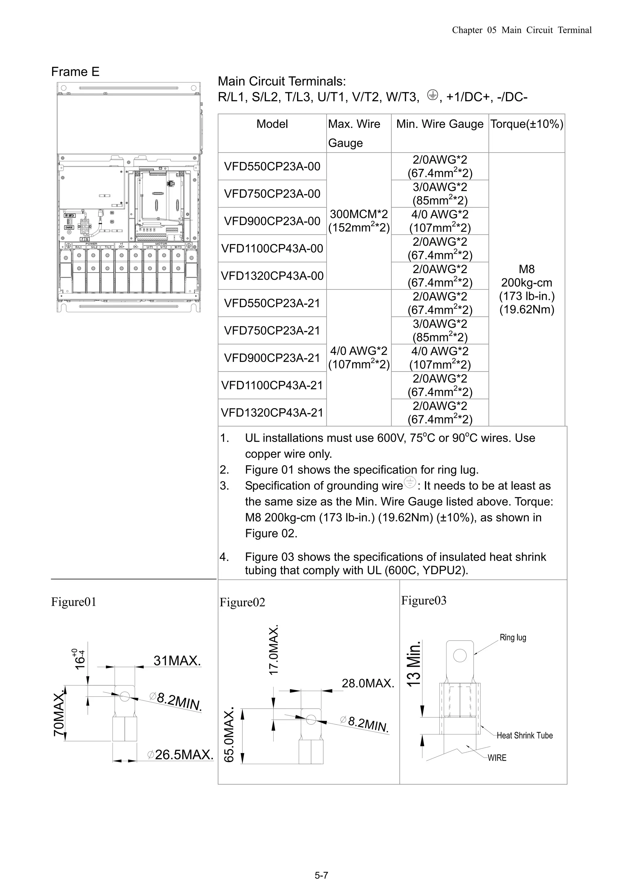
![Chapter 05 Main Circuit Terminal
5-11
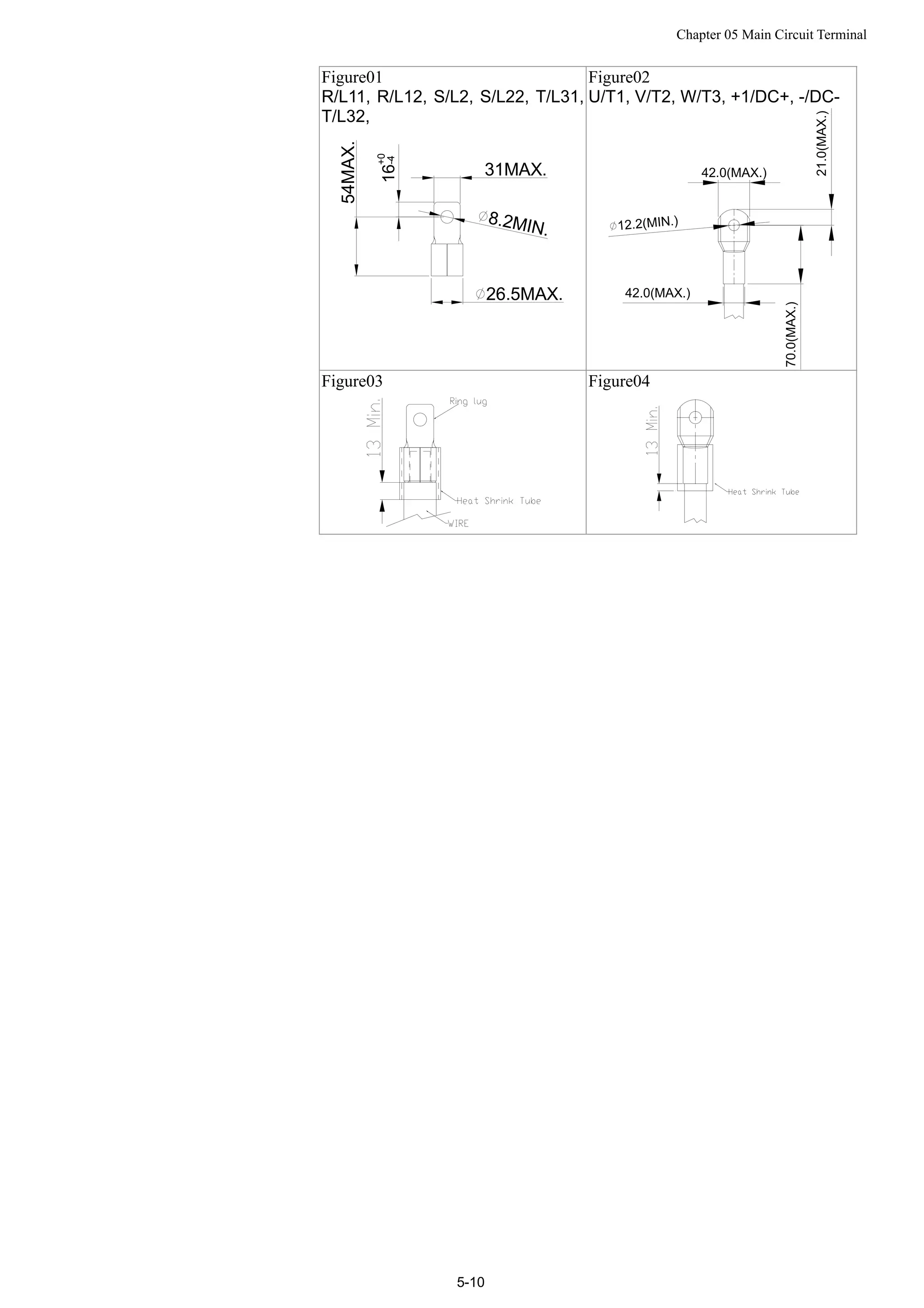
Frame H
Main circuit terminals:
R/11,R12,S/21,S/22,T/31,T/32, U/T1, V/T2, W/T3, +1/DC+, -/DC-
Model Max. Wire
Gauge
Min. Wire Gauge Torque(±10%)
VFD3150CP43A-00 4/0 AWG*4(107mm2
*4)
VFD3550CP43A-00 250MCM*4(127mm2
*4)
VFD4000CP43A-00 300MCM*4(152mm2
*4)
VFD4000CP43C-00 300MCM*4(152mm2
*4)
VFD3150CP43C-00 4/0 AWG*4(107mm2
*4)
VFD3550CP43C-00 250MCM*4(127mm2
*4)
VFD3150CP43C-21 4/0 AWG*4(107mm2*4)
VFD3550CP43C-21 250MCM*4(127mm2*4)
VFD4000CP43C-21
300MCM*4
(152mm2
*4)
300MCM*4(152mm2*4)
M8
200kg-cm
(173 lb-in.)
(19.62Nm)
1. UL installations must use 600V, 75℃ or 90℃ wire. Use copper wire
only.
2. Figure 1 shows the specification for using the ring lug.
3. Specification of grounding wire : 300MCM*4 [152 mm2
*4],
Torque: M8 180kg-cm (156 lb-in.) (17.64Nm) (±10%), as shown in
figure 1.
4. Figure 2 shows the specifications of heat shrink tubing that comply
with UL (600C, YDPU2).
Figure01 Figure02](https://image.slidesharecdn.com/deltacp2000men20120331-140612232906-phpapp02/75/Delta-cp2000-m_en_20120331-59-2048.jpg)
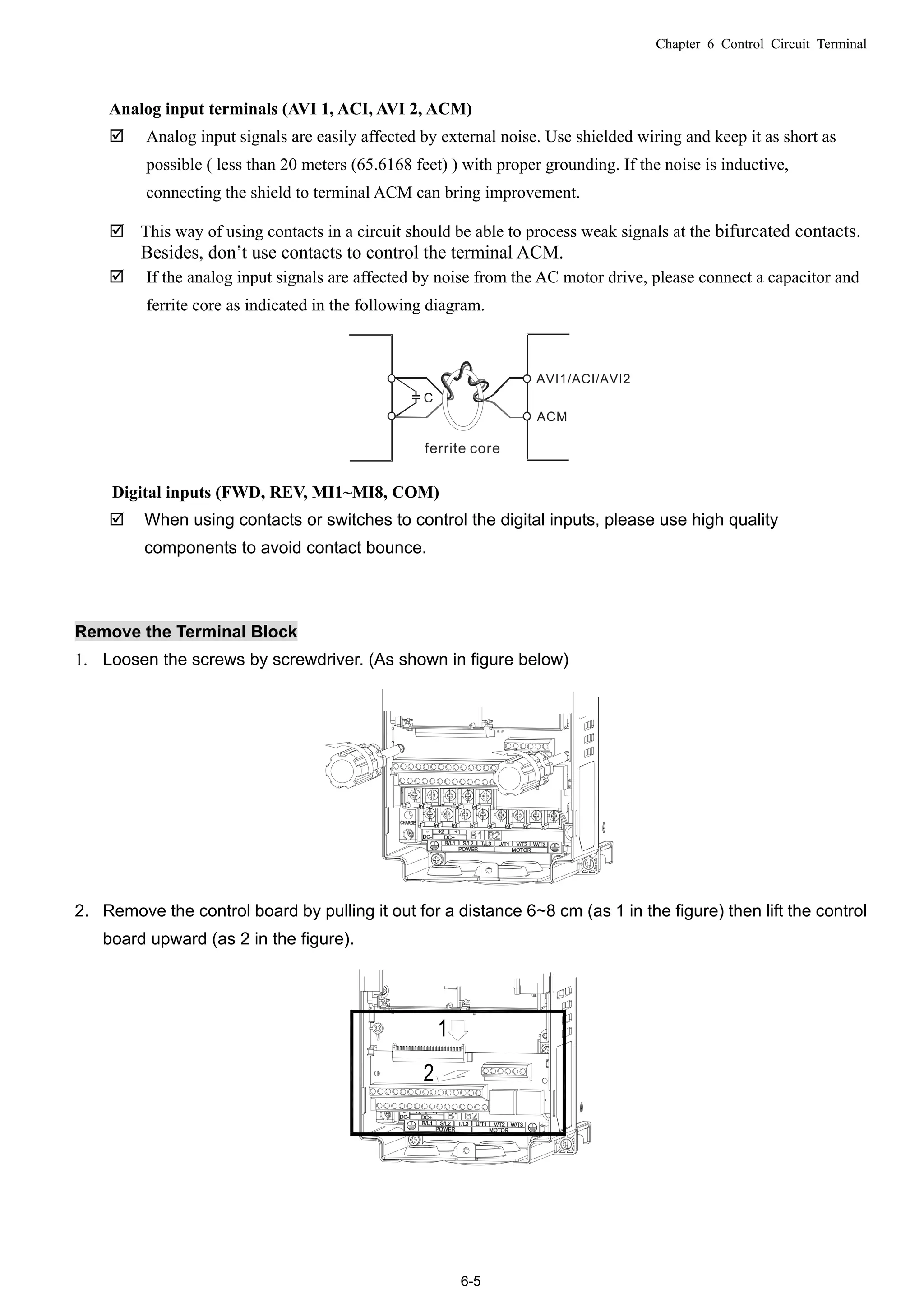
![Chapter 6 Control Circuit Terminal
6-1
06 Control Circuit Terminal
For multi-function input and output terminal, remove the top cover before wiring
The figures shown in the diagram below are for reference only.
Remove the cover for wiring. Frame A~H
Frame A&B
Loosen the screws and press the tabs
on both sides to remove the cover.
Screw torque: 12~15Kg-cm [10.4~13lb-in.]
Frame C&D
Screw torque: 12~15Kg-cm [10.4~13lb-in.]
Frame E
Screw torque: 12~15Kg-cm [10.4~13lb-in.] Slightly lift the cover then pull outward for removal.](https://image.slidesharecdn.com/deltacp2000men20120331-140612232906-phpapp02/75/Delta-cp2000-m_en_20120331-60-2048.jpg)
![Chapter 6 Control Circuit Terminal
6-2
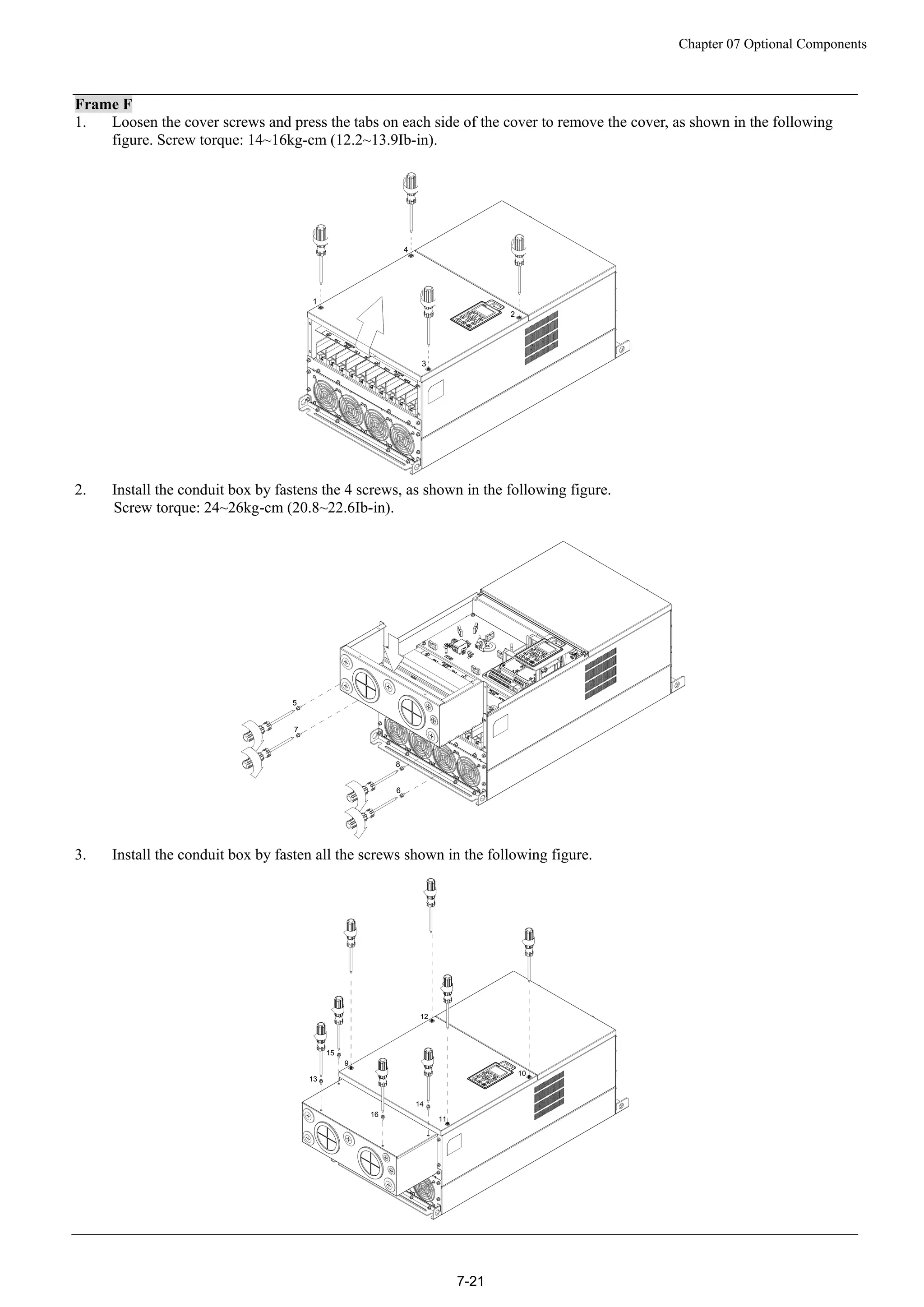
Frame F
Screw torque: 12~15Kg-cm [10.4~13lb-in.]
Slightly lift the cover then pull outward for removal.
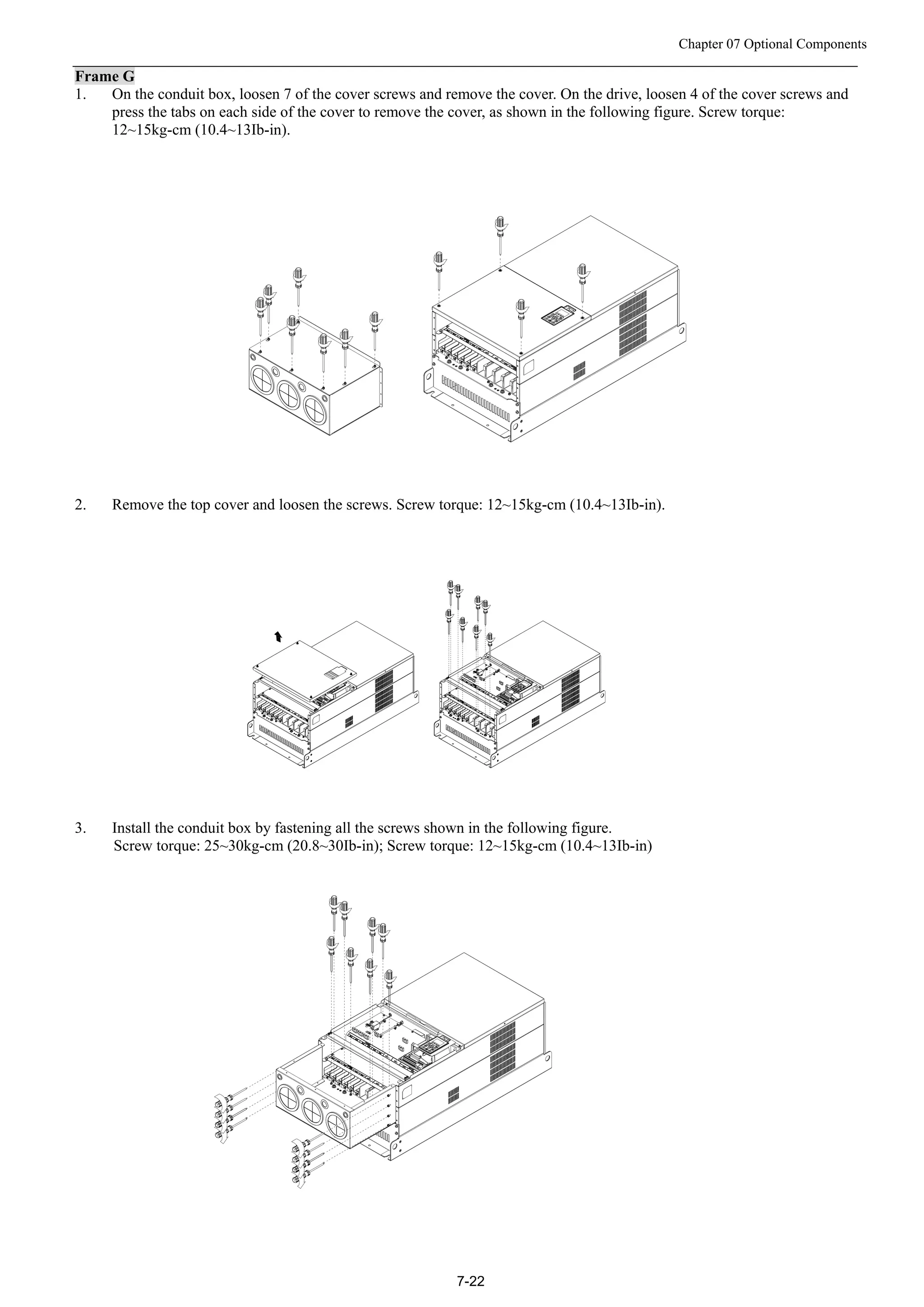
Frame G
Screw torque: 12~15Kg-cm [10.4~13lb-in.]
Slightly lift the cover then pull outward for removal.
Frame H
Screw torque: 14~16Kg-cm [12.15~13.89lb-in.] Slightly lift the cover then pull outward for removal.](https://image.slidesharecdn.com/deltacp2000men20120331-140612232906-phpapp02/75/Delta-cp2000-m_en_20120331-61-2048.jpg)
![Chapter 6 Control Circuit Terminal
6-3
Control Terminal Specifications
Wire Gauge: 26~16AWG(0.1281-1.318mm2
),
Torque: (A) 5kg-cm [4.31Ib-in.] (0.49Nm) (As shown in figure above)
(B) 8kg-cm [6.94Ib-in.] (0.78Nm) (As shown in figure above)
Wiring precautions:
Reserves 5mm and properly install the wire into the terminal; fasten the installation by a slotted
screwdriver. If the wire is stripped, sort the wire before install into the terminal.
Flathead screwdriver: blade width 3.5mm, tip thickness 0.6mm
In the figure above, the factory setting for S1-SCM is short circuit. The factory setting for
+24V-COM is short circuit and SINK mode (NPN); please refer to Chapter 4 Wiring for more detail.
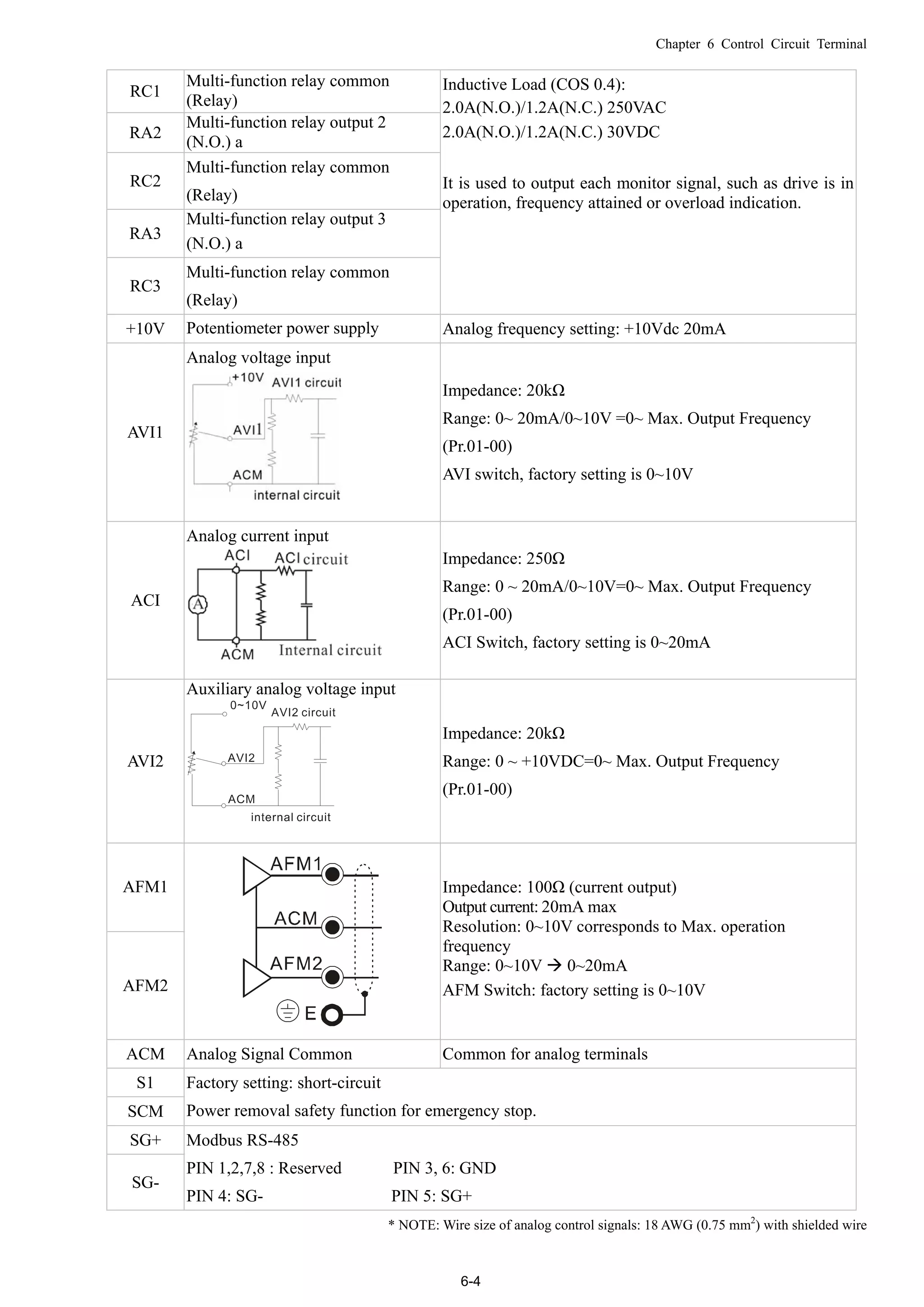
Terminals Terminal Function Factory Setting (NPN mode)
+24V
Digital control signal common
(Source)
+24V5% 200mA
COM
Digital control signal common
(Sink)
Common for multi-function input terminals
FWD Forward-Stop command
FWD-DCM:
ON forward running
OFF deceleration to stop
REV Reverse-Stop command
REV-DCM:
ON reverse running
OFF deceleration to stop
MI1
~
MI8
Multi-function input 1~8
Refer to parameters 02-01~02-08 to program the
multi-function inputs MI1~MI8.
ON: the activation current is 6.5mA≧11Vdc
OFF: leakage current tolerance is 10μA≦11Vdc
DCM Digital frequency signal common
RA1
Multi-function relay output 1
(N.O.) a
RB1
Multi-function relay output 1
(N.C.) b
Resistive Load:
5A(N.O.)/3A(N.C.) 250VAC
5A(N.O.)/3A(N.C.) 30VDC](https://image.slidesharecdn.com/deltacp2000men20120331-140612232906-phpapp02/75/Delta-cp2000-m_en_20120331-62-2048.jpg)
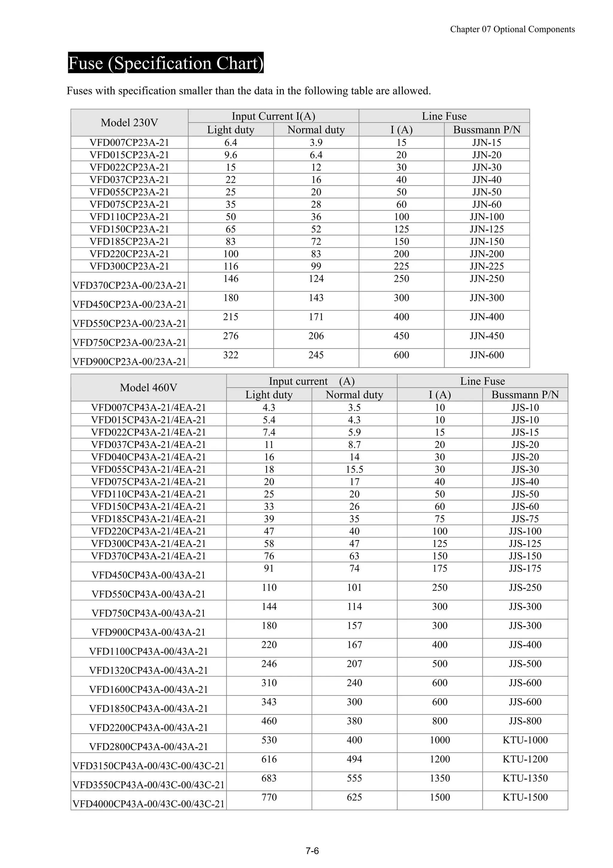
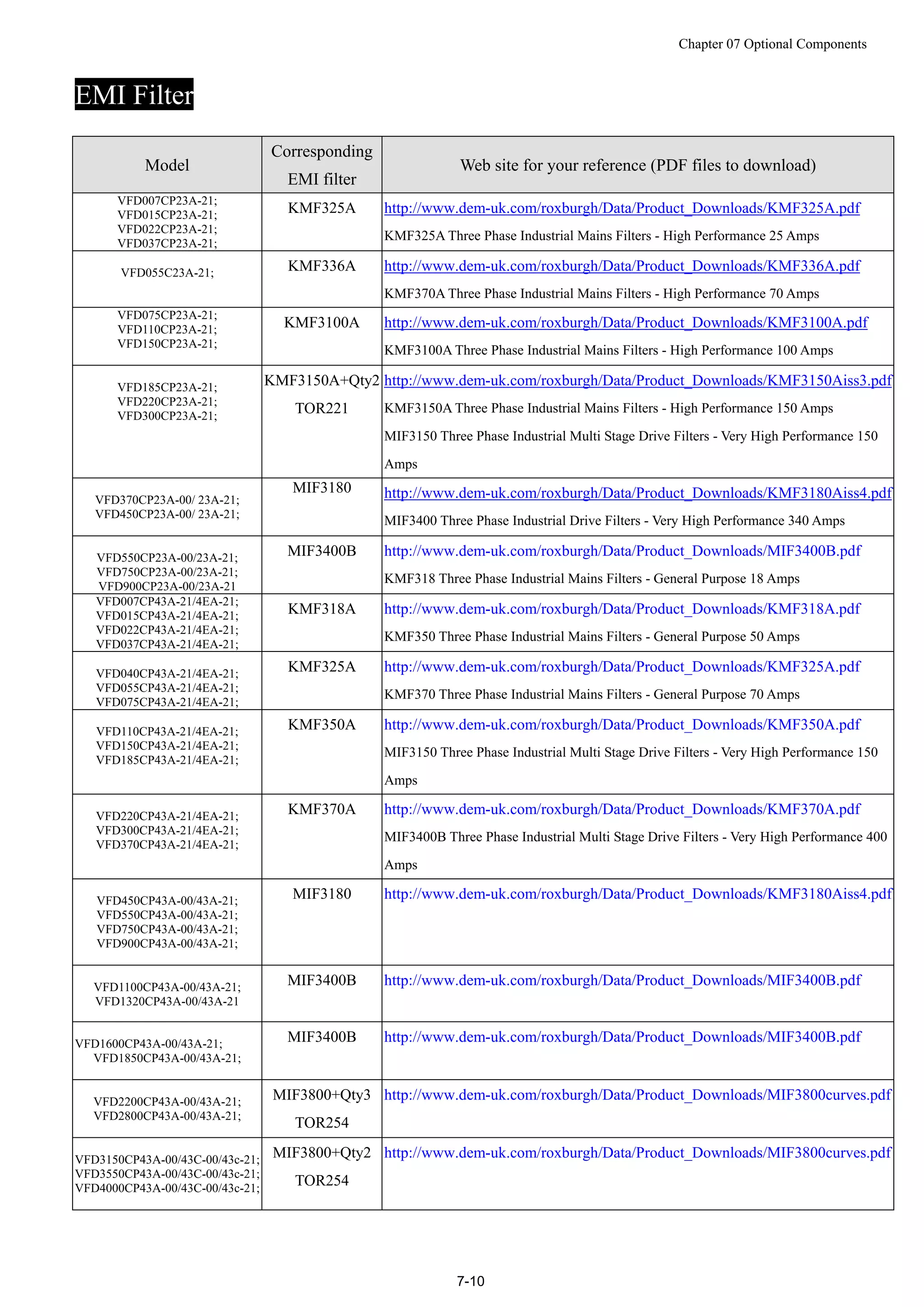
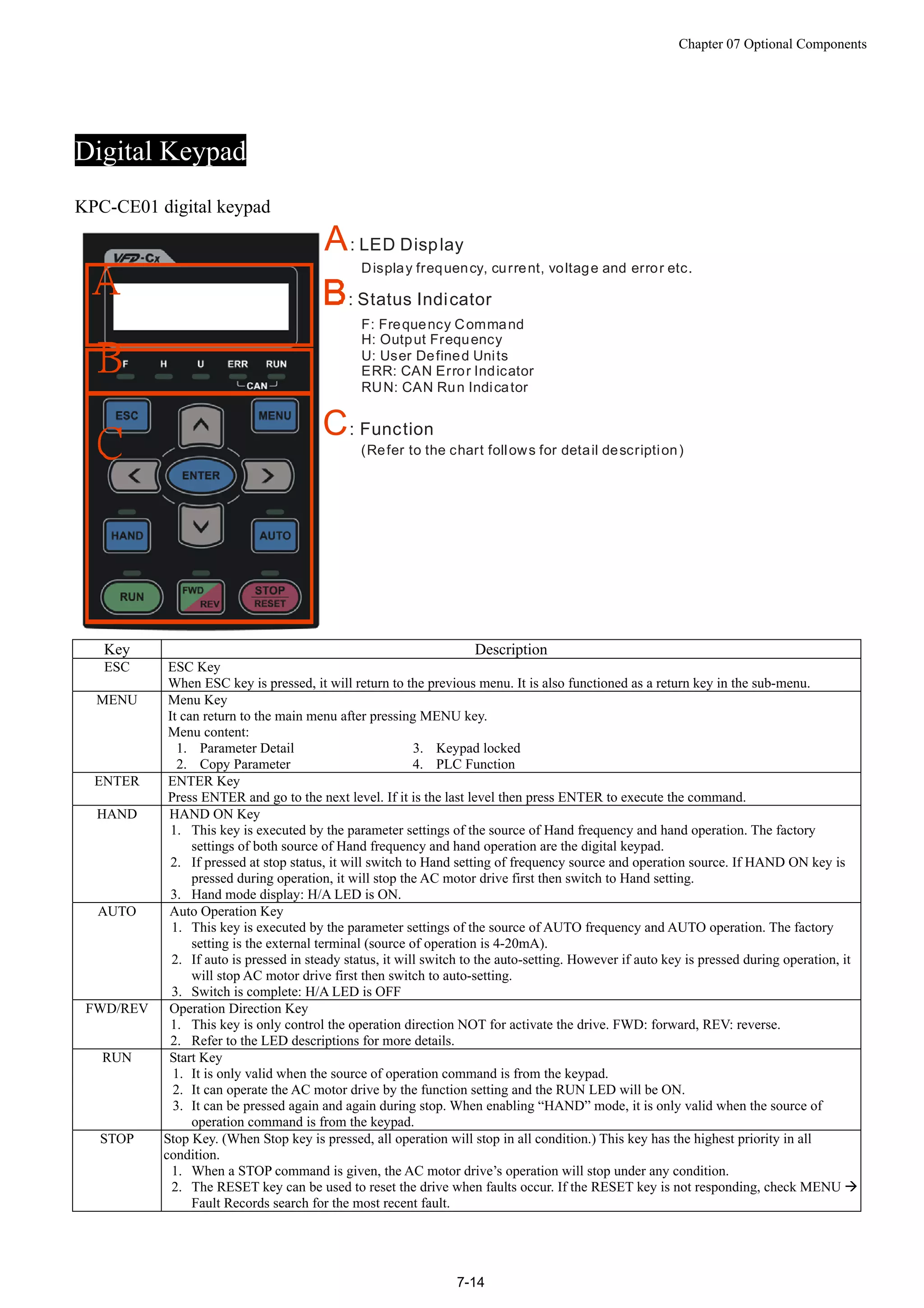
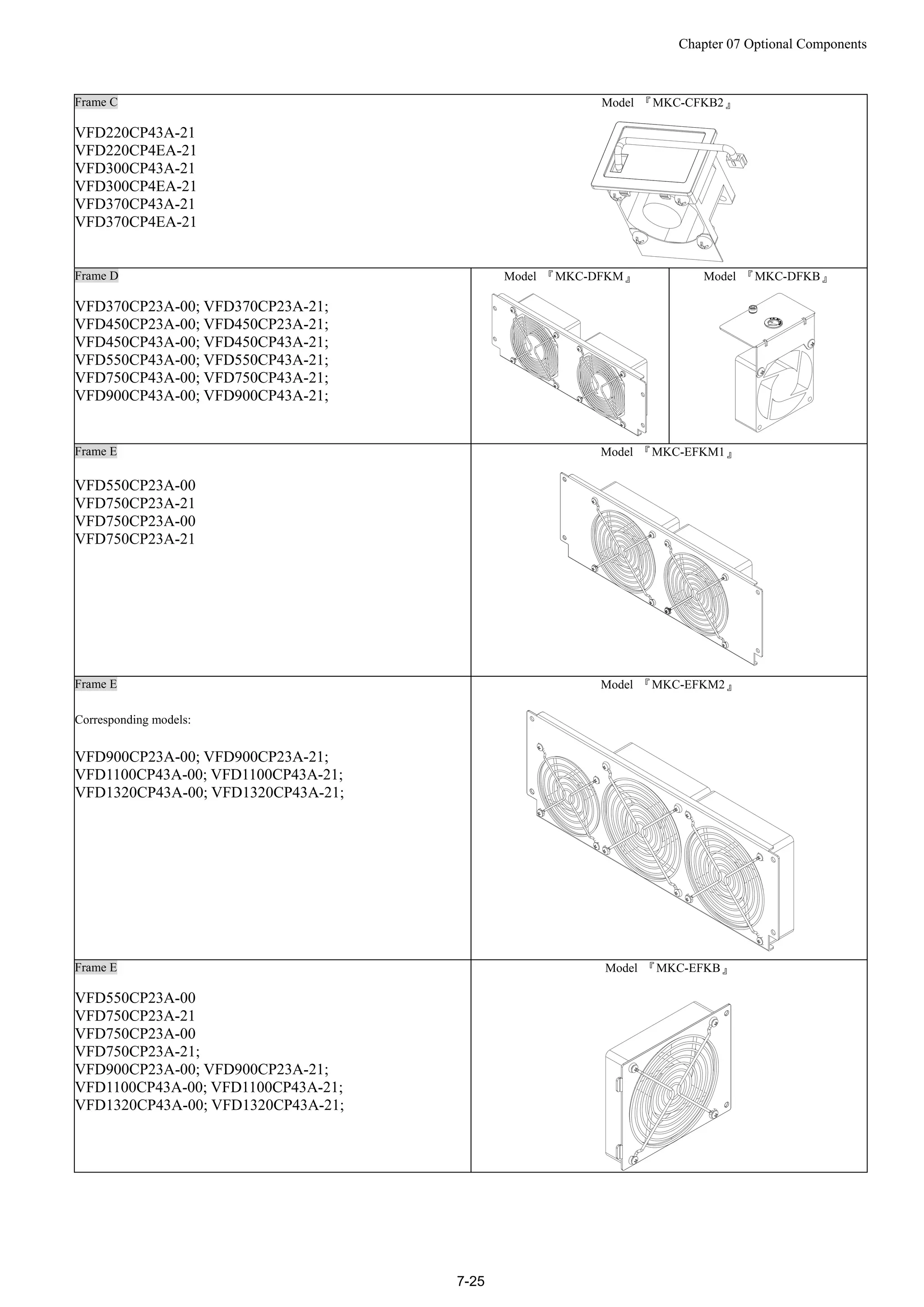
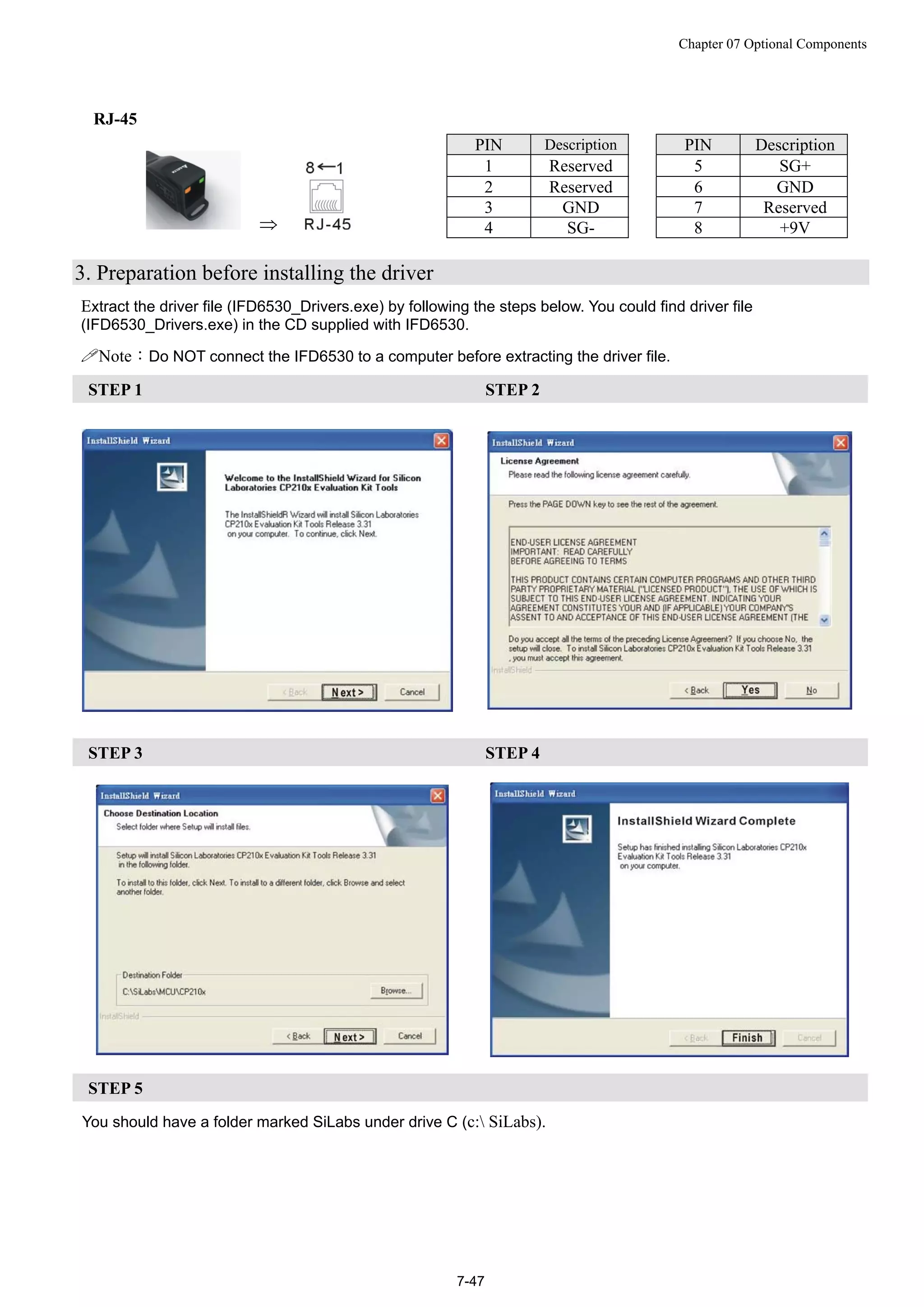
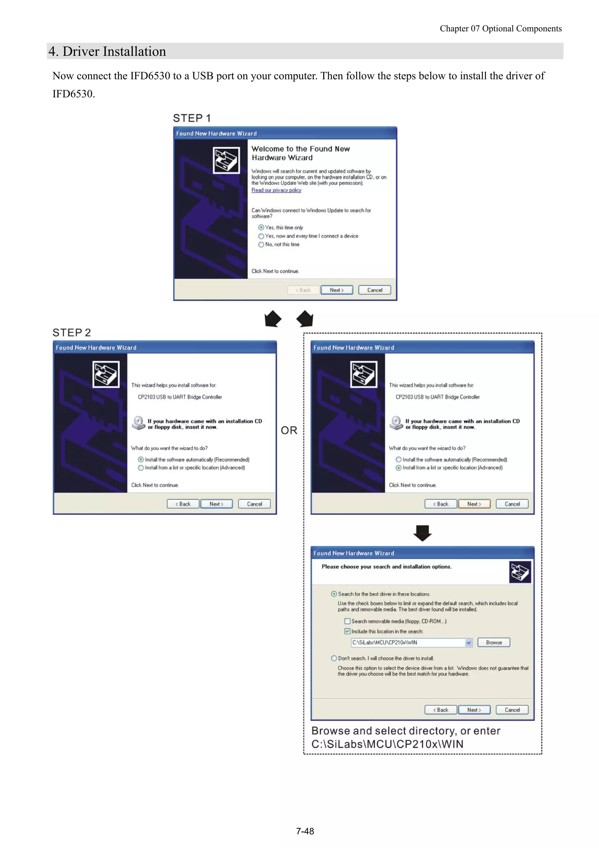
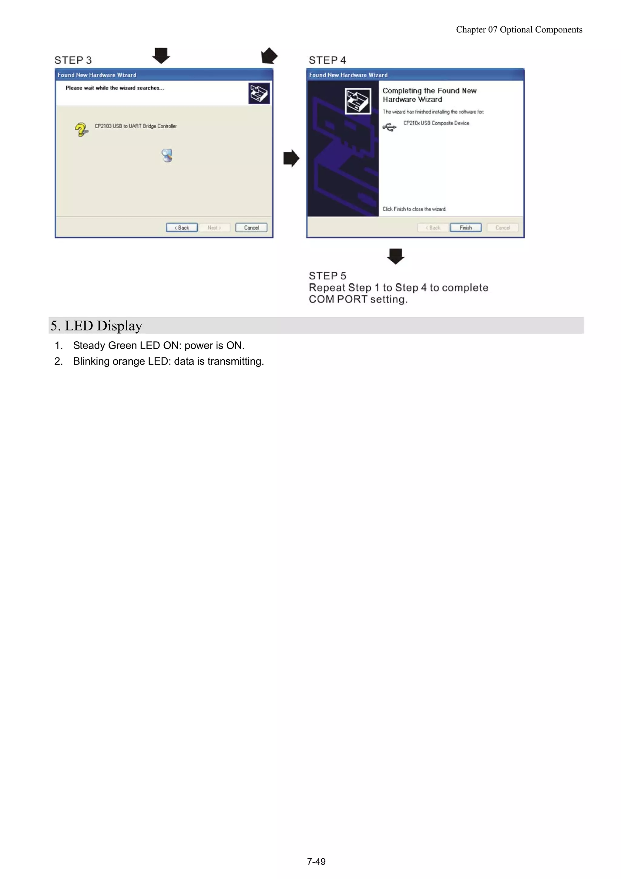
![Chapter 07 Optional Components
7-15
Dimensions: mm [inch]](https://image.slidesharecdn.com/deltacp2000men20120331-140612232906-phpapp02/75/Delta-cp2000-m_en_20120331-79-2048.jpg)
![Chapter 07 Optional Components
7-16
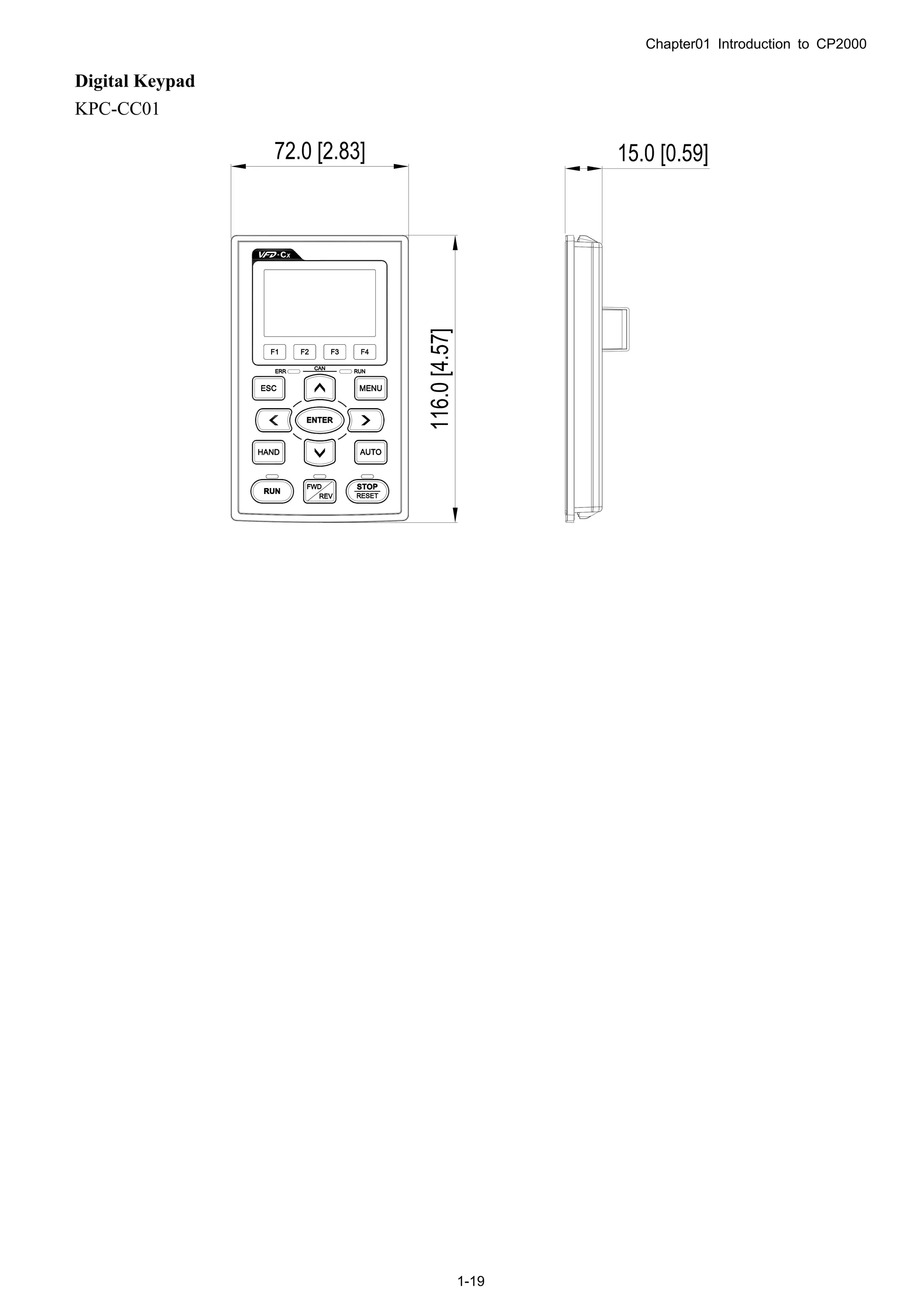
Panel Mounting Kit (MKC-KPPK)
For MKC-KPPK model, user can choose wall mounting or embedded mounting, protection level is IP56.
Applicable to the digital keypads (KPC-CC01 & KPC-CE01).
Wall Mounting Embedded Mounting
accessories*1
Screw *4 ~M4*p 0.7 *L8mm
Torque: 10-12kg-cm (8.7-10.4lb-in.)
accessories*2
Screw *4 ~M4*p 0.7 *L8mm
Torque: 10-12kg-cm (8.7-10.4lb-in.)
Panel cutout dimension Unit: mm [inch] Panel cutout dimension Unit: mm [inch]
Normal cutout dimension
Panel
thickness
1.2mm 1.6mm 2.0mm
A 66.4 [2.614]
B 110.2 [4.339] 111.3 [4.382] 112.5 [4.429]
*Deviation: ±0.15mm /±0.0059inch
Cutout dimension (Waterproof level: IP56)
Panel
thickness
1.2mm 1.6mm 2.0mm
A 66.4 [2.614]
B 110.8 [4.362]
*Deviation: ±0.15mm /±0.0059inch](https://image.slidesharecdn.com/deltacp2000men20120331-140612232906-phpapp02/75/Delta-cp2000-m_en_20120331-80-2048.jpg)

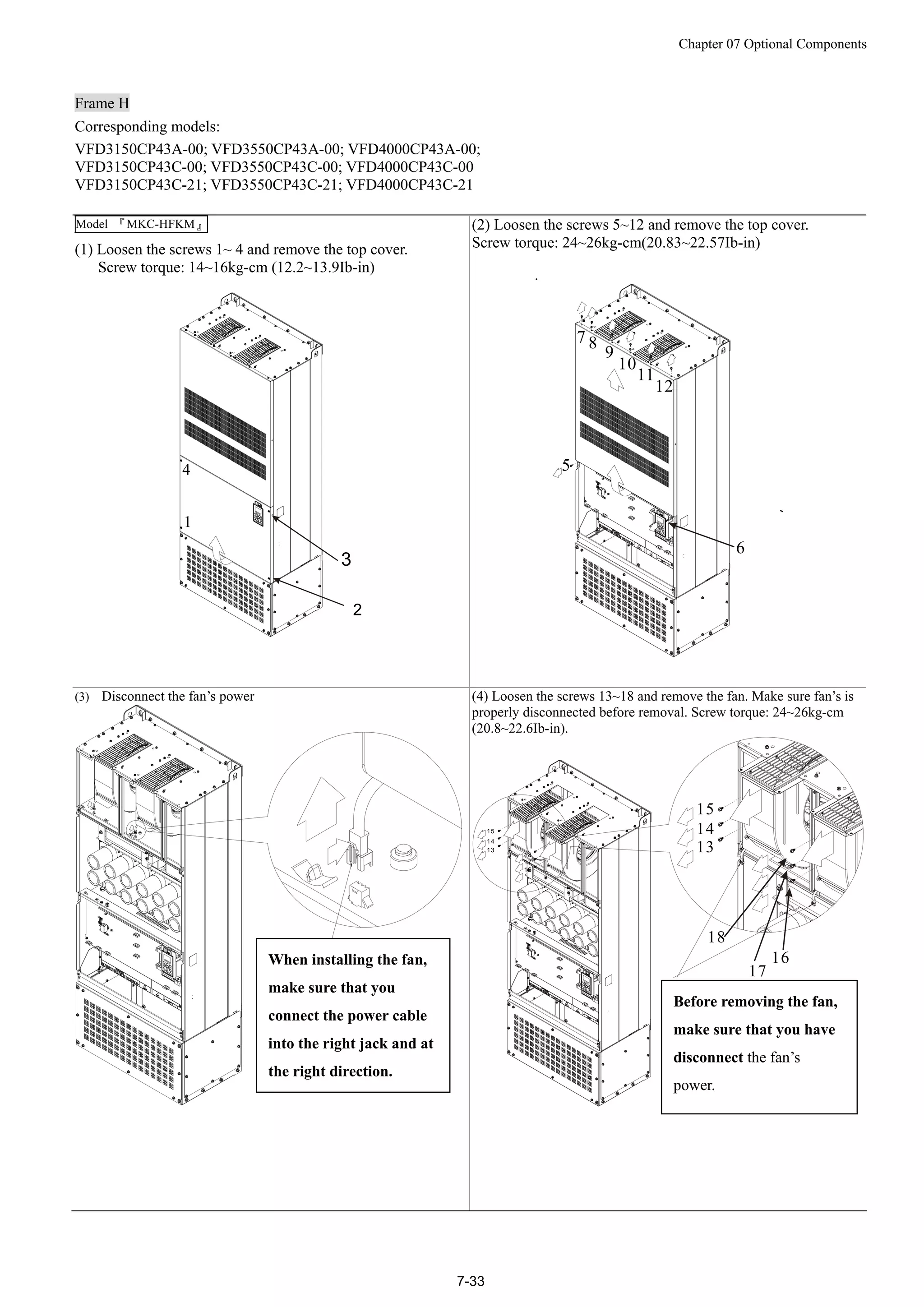
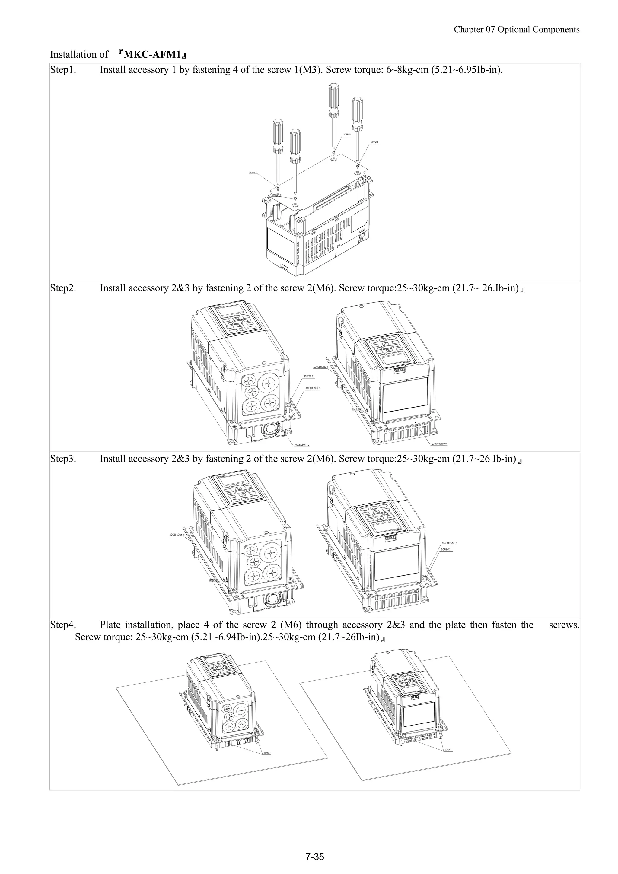
![Chapter 07 Optional Components
7-34
Flange Mounting Kit
Corresponding frames: Frames A ~F
Frame A
『MKC-AFM1』
Corresponding models: VFD022CP23A-21; VFD037CP23A-21; VFD037CP43A-21
Accessories 1*1 piece Accessories 2*2 pieces Accessories 3*2 pieces
Screw 1 *4 pieces
M3*P 0.5; L=6mm
Screws 2*8 pieces
M6*P 1.0; L=16mm
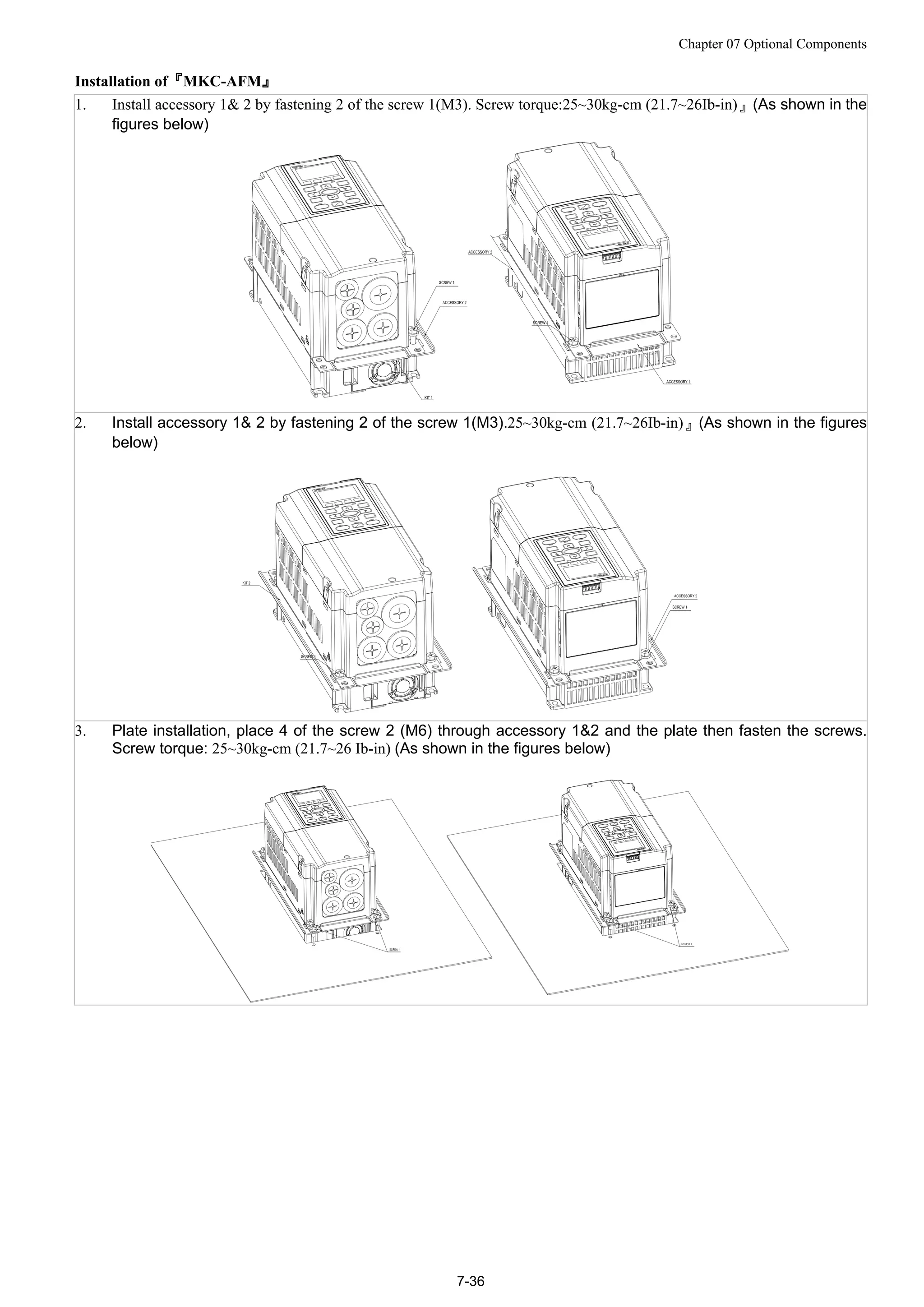
『MKC-AFM』
Corresponding models: VFD007CP23A-21; VFD015CP23A-21; VFD055CP23A-21;
VFD007CP43A/4EA-21; VFD015CP43A/4EA-21; VFD022CP43A/4EA-21;
VFD040CP43A/4EA-21; VFD055CP43A/4EA-21; VFD075CP43A/4EA-21
Accessories 1*2 pieces Accessories 2*2 pieces
Screw 1*8 pieces
M6*P 1.0; L=16mm
Panel Cutout Diagrams Unit: mm [inch]](https://image.slidesharecdn.com/deltacp2000men20120331-140612232906-phpapp02/75/Delta-cp2000-m_en_20120331-98-2048.jpg)
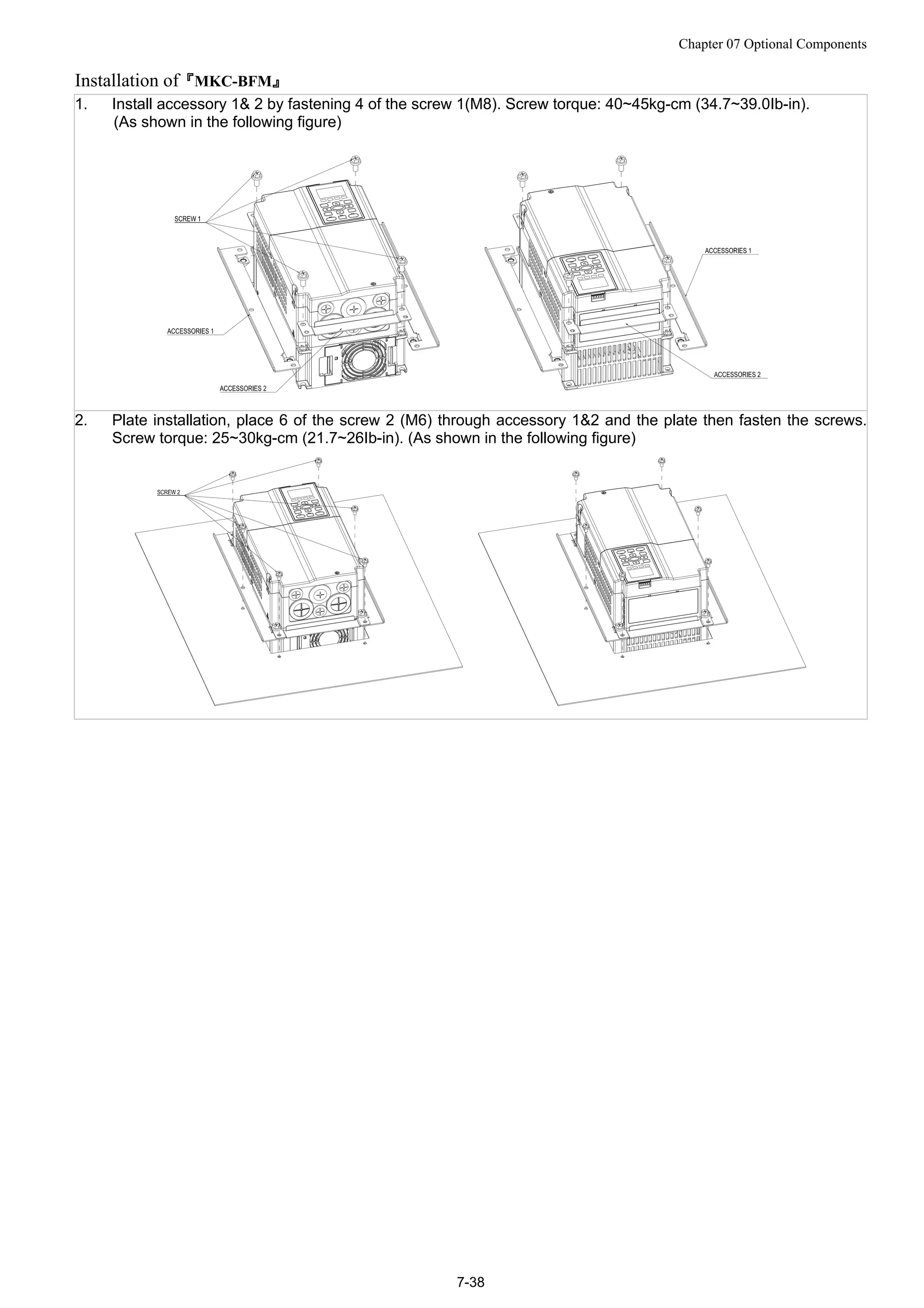
![Chapter 07 Optional Components
7-37
Frame B
『MKC-BFM』
Corresponding models: All Frame B models
Accessories 1*2 pieces Accessories 2*2pce
Screw 1 *4 pieces ~ M8*P 1.25;
Screw 2*6 pieces ~ M6*P 1.0;
Panel cutout diagram Unit : mm [inch]](https://image.slidesharecdn.com/deltacp2000men20120331-140612232906-phpapp02/75/Delta-cp2000-m_en_20120331-101-2048.jpg)
![Chapter 07 Optional Components
7-39
Frame C
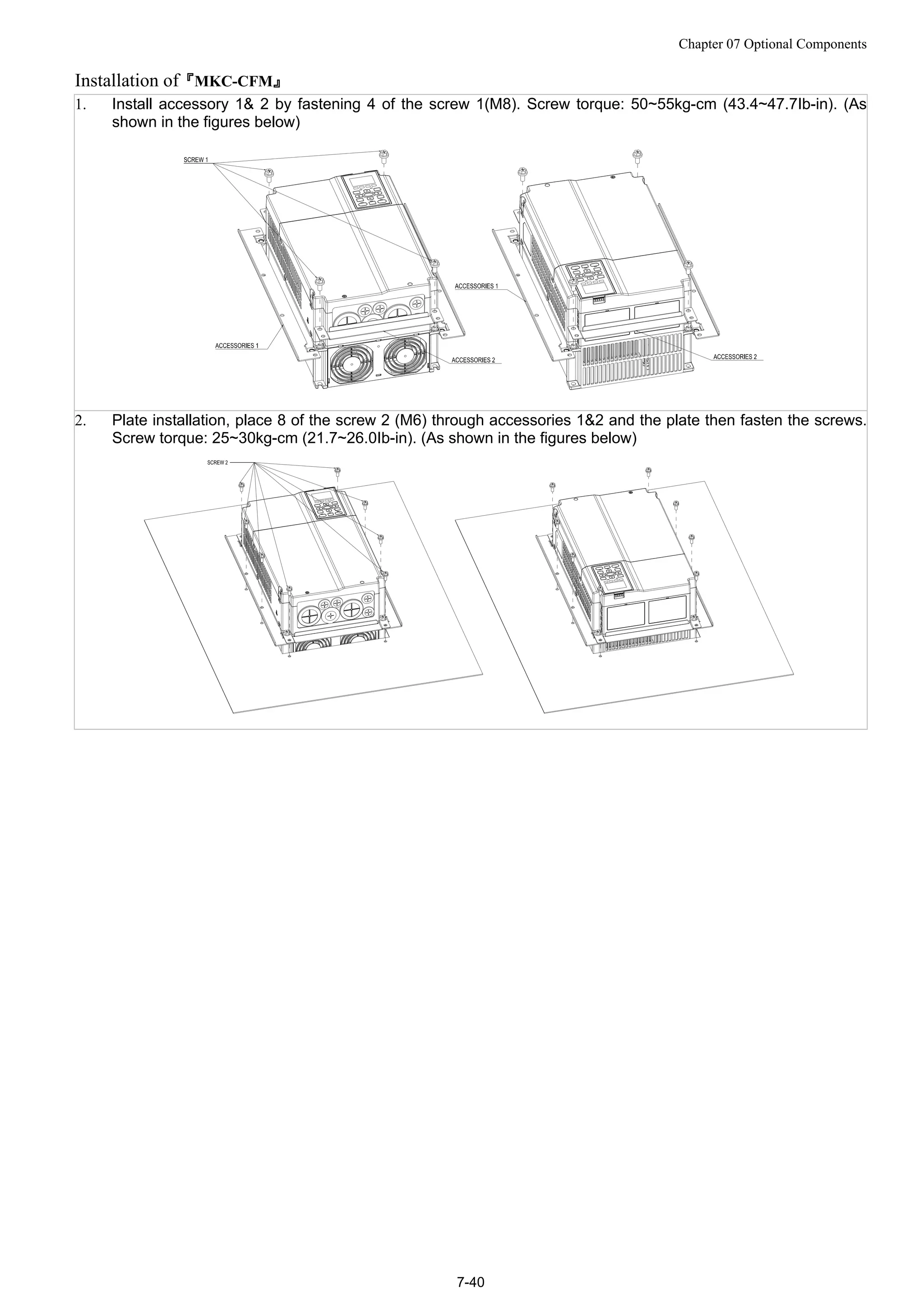
『MKC-CFM』
Corresponding models: All Frame C models.
Accessories 1*2pce Accessories 2*2pce
Screw 1*4pce ~ M8*P 1.25;
Screw 2*8 pieces~ M6*P 1.0;
Panel cutout diagram Unit: :mm [inch]](https://image.slidesharecdn.com/deltacp2000men20120331-140612232906-phpapp02/75/Delta-cp2000-m_en_20120331-103-2048.jpg)
![Chapter 07 Optional Components
7-41
Frame D
Panel Cutout Diagrams Unit: mm [inch]
M10*P1.5(4X)
OR 11.0[0.43](4X)](https://image.slidesharecdn.com/deltacp2000men20120331-140612232906-phpapp02/75/Delta-cp2000-m_en_20120331-105-2048.jpg)
![Chapter 07 Optional Components
7-42
Frame E
Panel Cutout Diagrams Unit :mm [inch]](https://image.slidesharecdn.com/deltacp2000men20120331-140612232906-phpapp02/75/Delta-cp2000-m_en_20120331-106-2048.jpg)
![Chapter 07 Optional Components
7-44
Frame F
Panel Cutout Diagram Unit: mm [inch]](https://image.slidesharecdn.com/deltacp2000men20120331-140612232906-phpapp02/75/Delta-cp2000-m_en_20120331-108-2048.jpg)
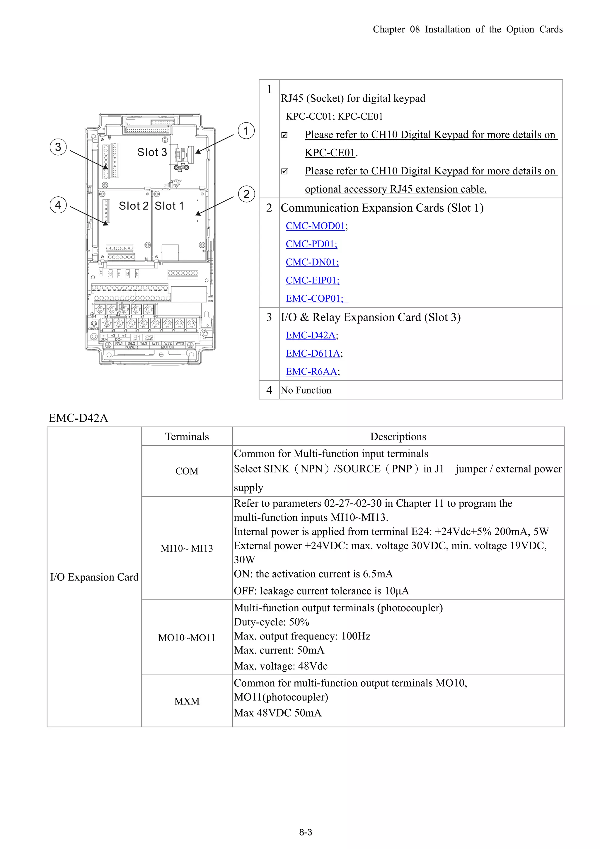
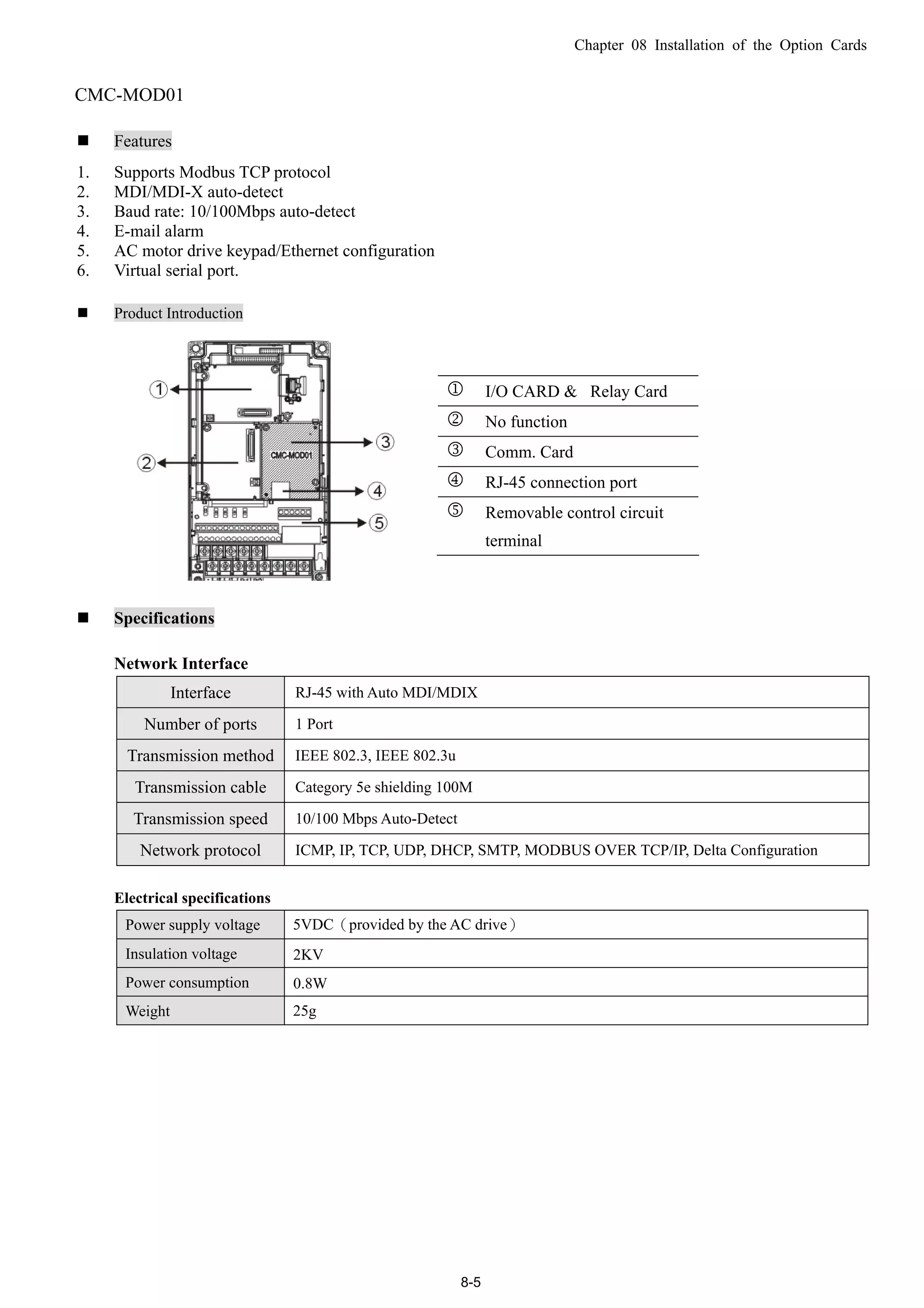
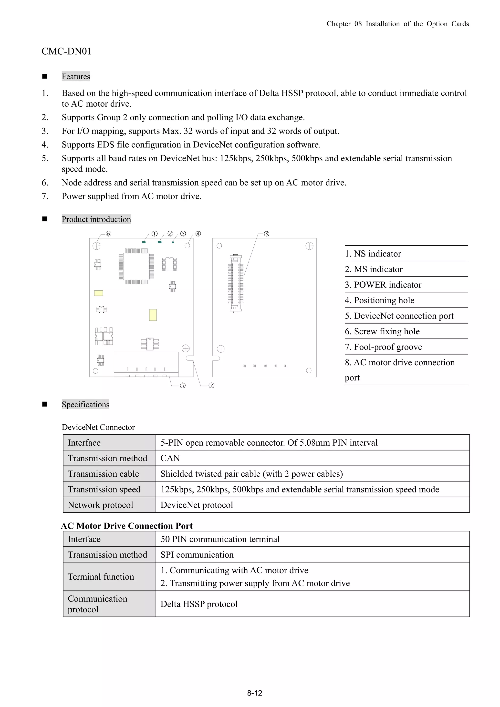
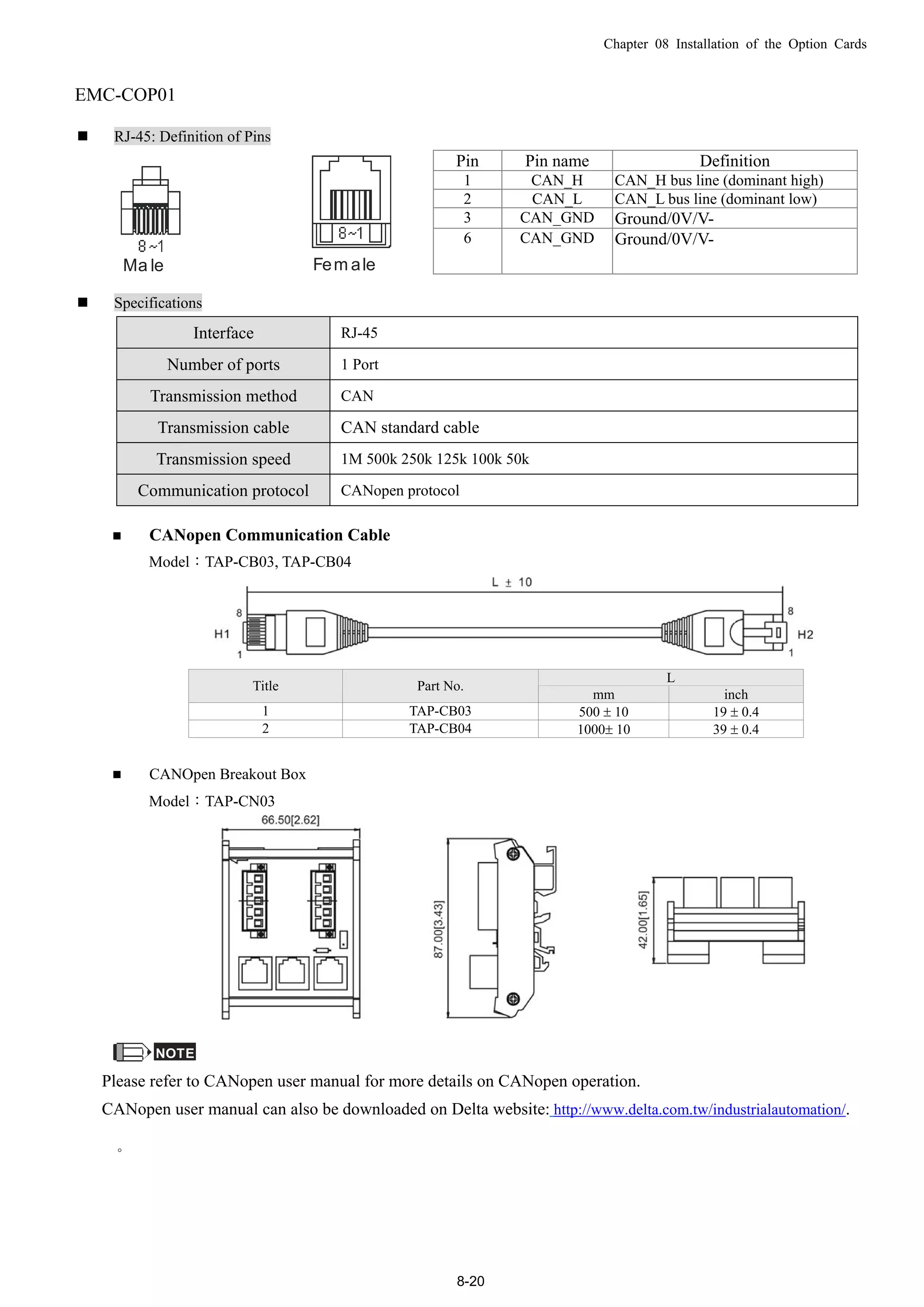
![Chapter 08 Installation of the Option Cards
8-1
08 Installation of the Option Cards(all optional)
Select applicable option cards for your drive or contact local distributor for professional advice. To prevent drive
damage during installation, please remove the digital keypad and the cover before wiring. Refer to the instructions
below.
Remove cover & keypad
Frame A, B and C: Screw Torque: 8~10Kg-cm [6.9~8.7lb-in.]
Frame D: Screw Torque: 8~10Kg-cm [6.9~8.7lb-in.]
Frame E: Screw Torque: 12~15Kg-cm [10.4~13lb-in.] As shown below, lift the cover then pull to remove it.](https://image.slidesharecdn.com/deltacp2000men20120331-140612232906-phpapp02/75/Delta-cp2000-m_en_20120331-114-2048.jpg)
![Chapter 08 Installation of the Option Cards
8-2
Frame F: Screw Torque: 12~15Kg-cm [10.4~13lb-in.] As shown below, lift the cover then pull to remove it.
Frame G: Screw Torque: 12~15Kg-cm [10.4~13lb-in.] As shown below, lift the cover then pull to remove it.
Frame H: Screw Torque: 14~16Kg-cm [12.15~13.89lb-in.]](https://image.slidesharecdn.com/deltacp2000men20120331-140612232906-phpapp02/75/Delta-cp2000-m_en_20120331-115-2048.jpg)
![Chapter 08 Installation of the Option Cards
8-4
EMC-D611A
Terminals Descriptions
AC AC power Common for multi-function input terminal (Neutral)
I/O Expansion Card
MI9~ MI14
Refer to Pr. 02.26~ Pr. 02.31 in Chapter 11for multi-function input
selection
Input voltage: 100~130VAC
Input frequency: 57~63Hz
Input impedance: 27Kohm
Terminal response time:
ON: 10ms
OFF: 20ms
EMC-R6AA
Terminals Descriptions
Relay Expansion
Card MO3 ~ MO13
Refer to Pr. 02.36~ Pr. 02.46 in Chapter 11 for multi-function output
selection
Resistive load:
5A(N.O.)/3A(N.C.) 250VAC
5A(N.O.)/3A(N.C.) 30VDC
Inductive load (COS 0.4)
2.0A(N.O.)/1.2A(N.C.) 250VAC
2.0A(N.O.)/1.2A(N.C.) 30VDC
It is used to output each monitor signal, such as drive is in operation,
frequency attained or overload indication.
Screw Specifications for Option Cards’ Terminals:
Wire Gauge 24~12AWG(0.205~3.31mm2
)
EMC-D42A
Torque 4Kg-cm [3.47Ib-in]
Wire Gauge 24~16AWG(0.205~1.31mm2
)
EMC-R6AA
Torque 6Kg-cm [5.21Ib-in]](https://image.slidesharecdn.com/deltacp2000men20120331-140612232906-phpapp02/75/Delta-cp2000-m_en_20120331-117-2048.jpg)
![Chapter 08 Installation of the Option Cards
8-6
Environment Specifications
Noise Immunity
ESD(IEC 61800-5-1,IEC 6100-4-2)
EFT(IEC 61800-5-1,IEC 6100-4-4)
Surge Teat(IEC 61800-5-1,IEC 6100-4-5)
Conducted Susceptibility Test(IEC 61800-5-1,IEC 6100-4-6)
Operation/Storage
Operation:-10°C ~ 50°C(Temperature),90%(Humidity)
Storage:-25°C ~ 70°C(Temperature),95%(Humidity)
Shock/Vibration resistance International Standard: IEC 61800-5-1,IEC 60068-2-6 / IEC 61800-5-1,IEC 60068-2-27
Install CMC-MOD01 on VFD-CP2000
1. Switch off the power supply of VFD-CP2000.
2. Open the front cover of VFD-CP2000.
3. Place the insulation spacer into the positioning pin at Slot 1 (shown in Figure 3), and aim the two holes on the
PCB at the positioning pin. Press the pin to clip the holes with the PCB (see Figure 4).
4. Screw up at torque 6 ~ 8 kg-cm (5.21 ~ 6.94 in-lbs) after the PCB is clipped with the holes (see Figure 5).
Slot 1Slot 2
Slot 3
[Figure3]
[Figure4]
[Figure5]](https://image.slidesharecdn.com/deltacp2000men20120331-140612232906-phpapp02/75/Delta-cp2000-m_en_20120331-119-2048.jpg)
![Chapter 08 Installation of the Option Cards
8-7
Communication parameter for VFD-CP2000 to connect to an Ethernet
Before VFD-CP2000 is linked to an Ethernet, set up the communication parameters shown in the table below.
Then Ethernet master will be able to read/write the frequency characters and control characters from/into
VFD-CP2000 after communication parameters are set.
CP2000 Functions Factory setting Explanation
00-20 Set up source of frequency 0 Frequency command from keypad
00-21
Set up source of operation
command
5 Operation command from communication card.
09-30
Communication decoding
method
0
The decoding method for Delta AC Motor Drive
(Delta AMD).
09-75 IP configuration 0 Static IP(0) / Dynamic IP (DHCP) (1)
09-76 IP address-1 192 IP address 192.168.1.5
09-77 IP address-2 168 IP address 192.168.1.5
09-78 IP address-3 1 IP address 192.168.1.5
09-79 IP address-4 5 IP address 192.168.1.5
09-80 Net mask-1 255 Net mask 255.255.255.0
09-81 Net mask-2 255 Net mask 255.255.255.0
09-82 Net mask-3 255 Net mask 255.255.255.0
09-83 Net mask-4 0 Net mask 255.255.255.0
09-84 Default gateway-1 192 Default gateway 192.168.1.1
09-85 Default gateway-2 168 Default gateway 192.168.1.1
09-86 Default gateway-3 1 Default gateway 192.168.1.1
09-87 Default gateway-4 1 Default gateway 192.168.1.1
Remove CMC- MOD01 from VFD-CP2000
1. Switch off the power supply of VFD-C2000.
2. Remove the two screws (see Figure 6).
3. Twist opens the card clip and inserts the slot type screwdriver to the hollow to prize the PCB off the card
clip (see Figure 7).
4. Twist opens the other card clip to remove the PCB (see Figure 8).
[Figure 6]
[Figure 7]
[Figure 8]](https://image.slidesharecdn.com/deltacp2000men20120331-140612232906-phpapp02/75/Delta-cp2000-m_en_20120331-120-2048.jpg)

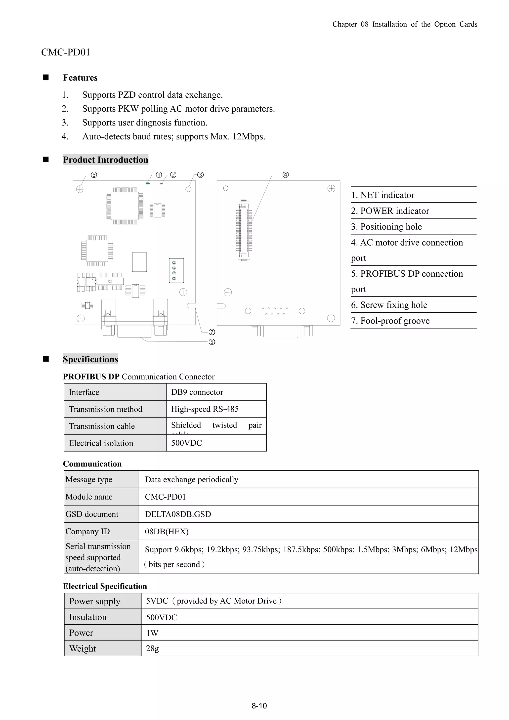
![Chapter 08 Installation of the Option Cards
8-15
CMC-EIP01
Features
1. Supports Modbus TCP and Ethernet/IP protocol
2. MDI/MDI-X auto-detect
3. Baud rate: 10/100Mbps auto-detect
4. AC motor drive keypad/Ethernet configuration
5. Virtual serial port
Product Introduction
[Figure1]
1. Screw fixing hole
2. Positioning hole
3. AC motor drive connection
port
4. LINK indicator
5. RJ-45 connection port
6. POWER indicator
7. Fool-proof groove
Specifications
Network Interface
Interface RJ-45 with Auto MDI/MDIX
Number of ports 1 Port
Transmission IEEE 802.3, IEEE 802.3u
Transmission cable Category 5e shielding 100M
Transmission speed 10/100 Mbps Auto-Detect
Network protocol
ICMP, IP, TCP, UDP, DHCP, HTTP, SMTP, MODBUS OVER TCP/IP, Ethernet/IP, Delta
Configuration
Electrical Specifications
Weight 25g
Insulation Voltage 500VDC
Power Consumption 0.8W
Power Supply Voltage 5VDC](https://image.slidesharecdn.com/deltacp2000men20120331-140612232906-phpapp02/75/Delta-cp2000-m_en_20120331-128-2048.jpg)
![Chapter 08 Installation of the Option Cards
8-16
Environment Specifications
Noise immunity
ESD (IEC 61800-5-1,IEC 61000-4-2)
EFT (IEC 61800-5-1,IEC 61000-4-4)
Surge Test (IEC 61800-5-1,IEC 61000-4-5)
Conducted Susceptibility Test (IEC 61800-5-1,IEC 61000-4-6)
Operation/storage
Operation: -10°C ~ 50°C (temperature), 90% (humidity), pollution degree 2
Storage: -25°C ~ 70°C (temperature), 95% (humidity), non-condensing
Vibration/shock
immunity
International standard: IEC 61800-5-1, IEC 60068-2-6/IEC 61800-5-1, IEC 60068-2-27
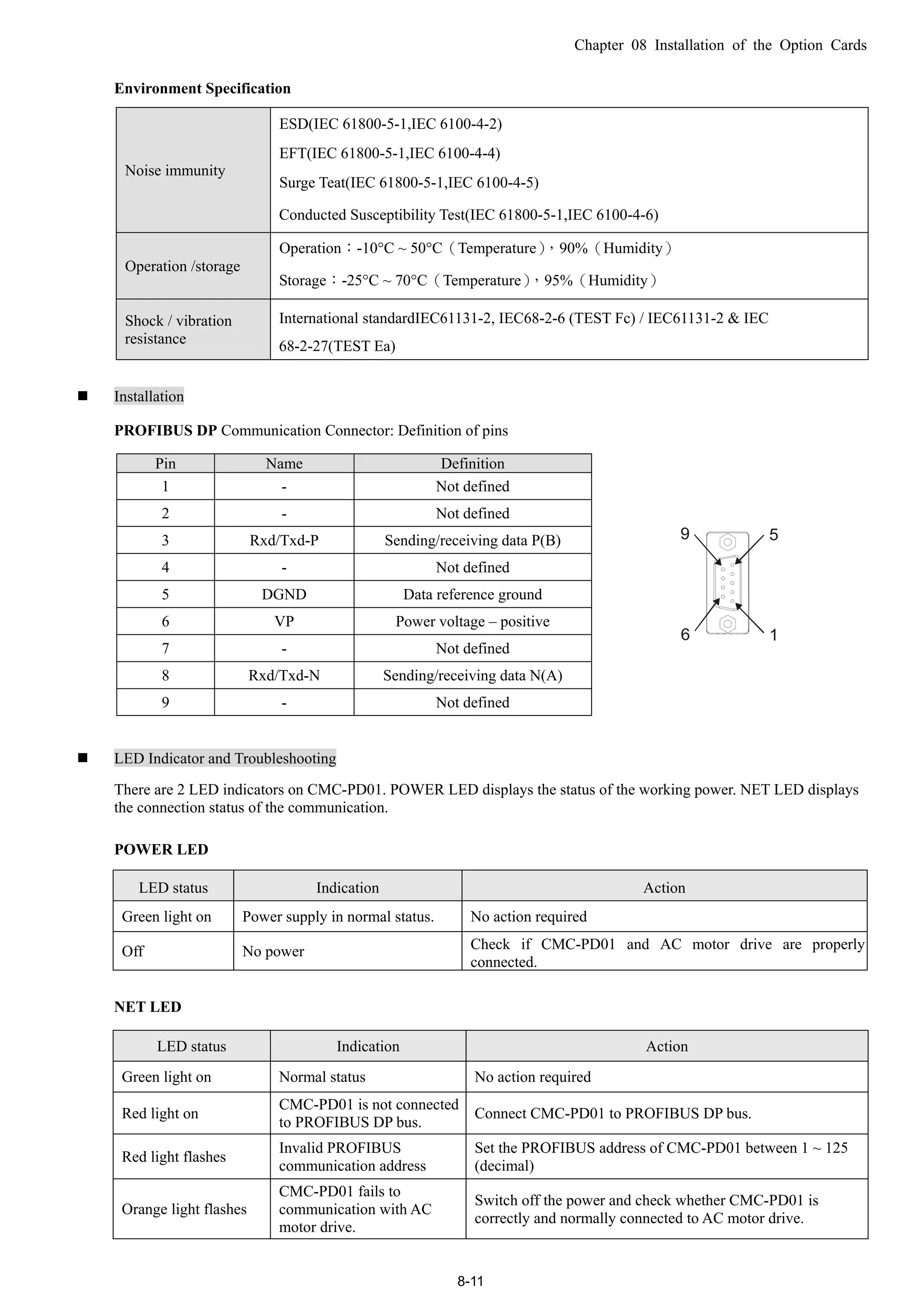
Installation
Connecting CMC-EIP01 to a Network
1. Turn off the power of AC motor drive.
2. Open the cover of AC motor drive.
3. Connect CAT-5e network cable to RJ-45 port on CMC-EIP01 (See
Figure 2).
[Figure 2]
RJ-45 connector: Definition of Pins
PIN Signal Definition PIN Signal Definition
1 Tx+
Positive pole for
data transmission
5 -- N/C
2 Tx-
Negative pole for
data transmission
6 Rx-
Negative pole for
data receiving
3 Rx+
Positive pole for
data receiving
7 -- N/C
4 -- N/C 8 -- N/C
Connecting CMC-EIP01 to VFD-CP2000
1. Switch off the power of AC motor drive.
2. Open the front cover of AC motor drive.
3. Place the insulation spacer into the positioning pin at Slot 1 (shown in Figure 3),
and aim the two holes on the PCB at the positioning pin. Press the pin to clip the holes
with the PCB (see Figure 4).
4. Screw up at torque 6 ~ 8 kg-cm (5.21 ~ 6.94 in-lbs) after the PCB is clipped with the holes
(see Figure 5).
Slot 1Slot 2
Slot 3
[Figure 3] [Figure 4]](https://image.slidesharecdn.com/deltacp2000men20120331-140612232906-phpapp02/75/Delta-cp2000-m_en_20120331-129-2048.jpg)
![Chapter 08 Installation of the Option Cards
8-17
[Figure 5]
Communication parameter for VFD-CP2000 to connect to an Ethernet
Before VFD-CP2000 is linked to an Ethernet, set up the communication parameters shown in the table below.
Then Ethernet master will be able to read/write the frequency characters and control characters from/into
VFD-CP2000 after communication parameters are set.
CP2000 Parameters Functions
Factory setting
(Dec)
Explanation
00-20
Set up source of
frequency command
0 Frequency command from keypad
00-21
Set up source of
operation command
5
Operation command from communication
card.
09-30
Communication
decoding method
0
The decoding method for Delta AC Motor
Drive (Delta AMD).
09-75 IP configuration 0 Static IP(0) / Dynamic IP
09-76 IP address-1 192 IP address 192.168.1.5
09-77 IP address-2 168 IP address 192.168.1.5
09-78 IP address-3 1 IP address 192.168.1.5
09-79 IP address-4 5 IP address 192.168.1.5
09-80 Net mask-1 255 Net mask 255.255.255.0
09-81 Net mask-2 255 Net mask 255.255.255.0
09-82 Net mask-3 255 Net mask 255.255.255.0
09-83 Net mask-4 0 Net mask 255.255.255.0
09-84 Default gateway-1 192 Default gateway 192.168.1.1
09-85 Default gateway-2 168 Default gateway 192.168.1.1
09-86 Default gateway-3 1 Default gateway 192.168.1.1
09-87 Default gateway-4 1 Default gateway 192.168.1.1](https://image.slidesharecdn.com/deltacp2000men20120331-140612232906-phpapp02/75/Delta-cp2000-m_en_20120331-130-2048.jpg)
![Chapter 08 Installation of the Option Cards
8-18
Remove CMC-EIP01 from VFD-CP2000
1.Switch off the power supply of VFD-CP2000.
2.Remove the two screws (see Figure 6).
3.Twist opens the card clip and inserts the slot type screwdriver to the hollow to prize the PCB off the card
clip (see Figure 7).
4.Twist opens the other card clip to remove the PCB (see Figure 8).
[Figure 6] [Figure 7]
[Figure 8]
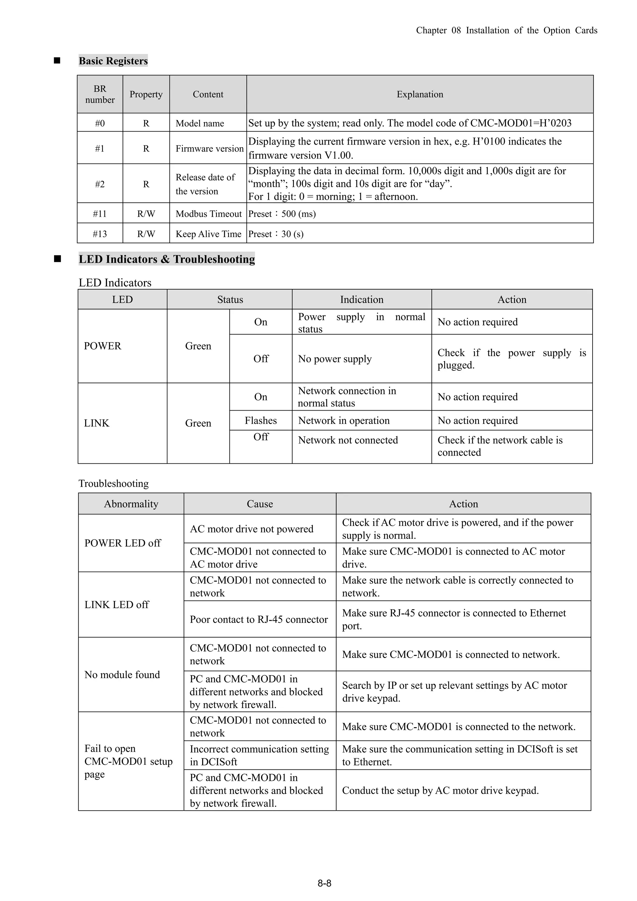
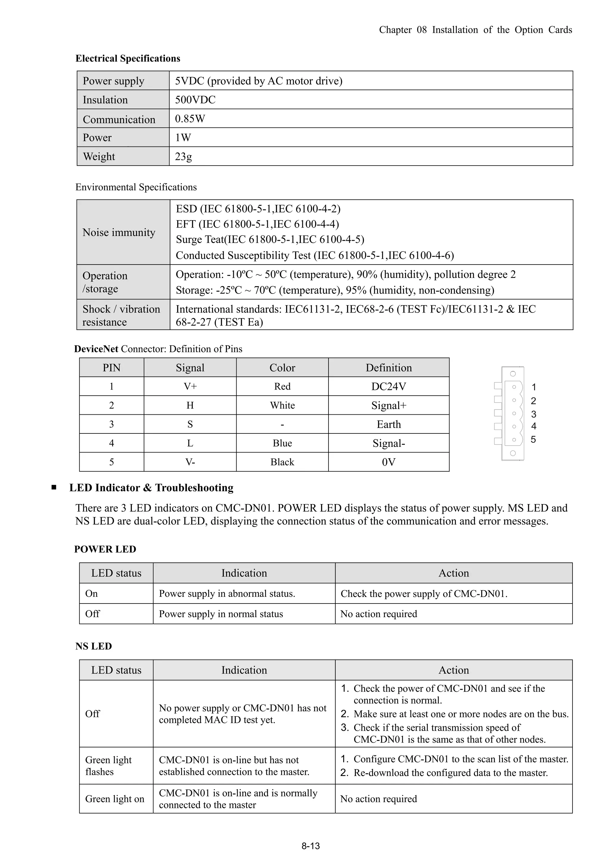
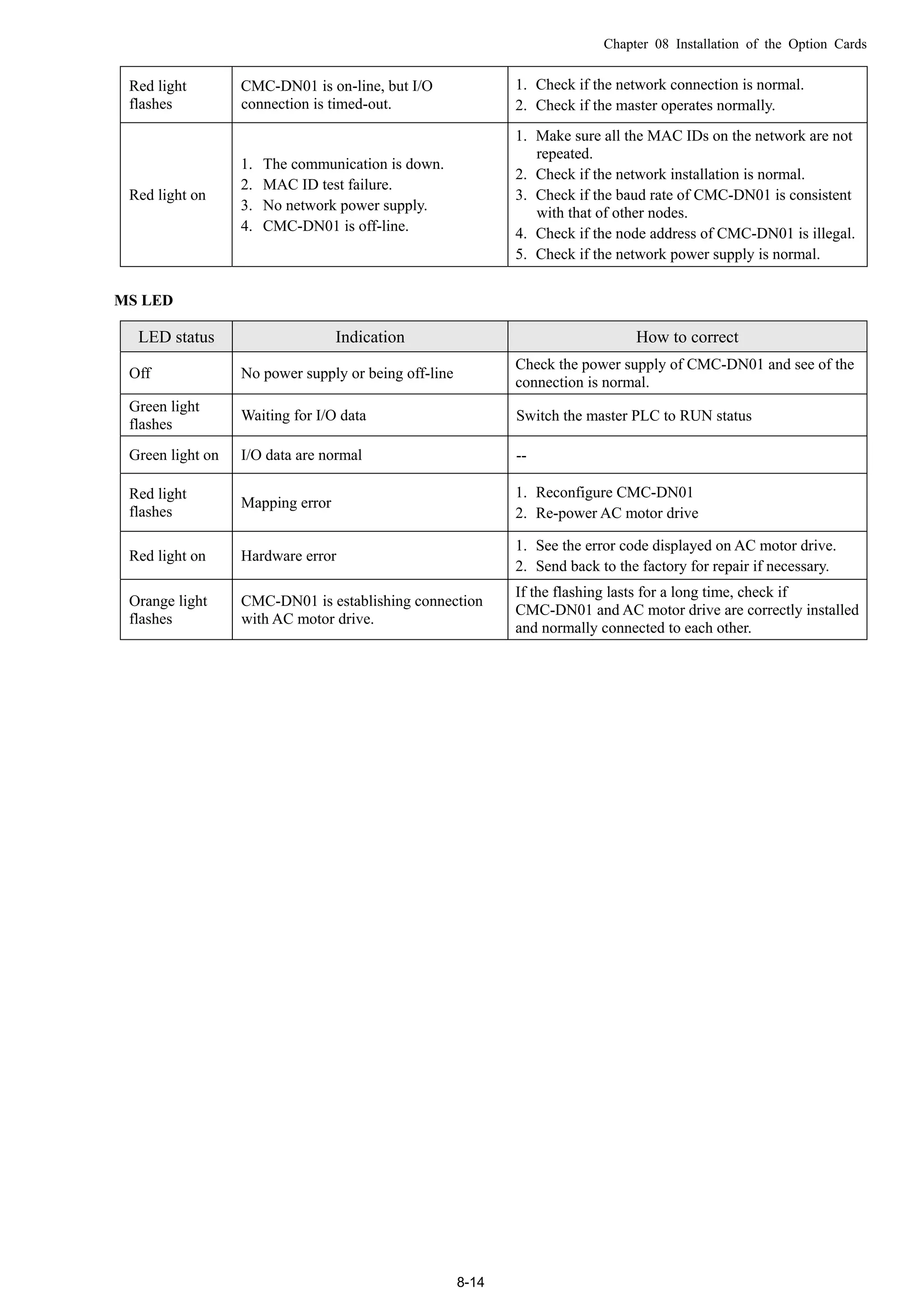
LED Indicators & Troubleshooting
There are 2 LED indicators on CMC-EIP01. The POWER LED displays the status of power supply, and the
LINK LED displays the connection status of the communication.
LED Indicators
LED Status Indication Action
On Power supply in normal status No action required
POWER Green
Off No power supply Check the power supply.
On Network connection in normal status No action required
Flashes Network in operation No action requiredLINK Green
Off Network not connected
Check if the network cable is
connected.
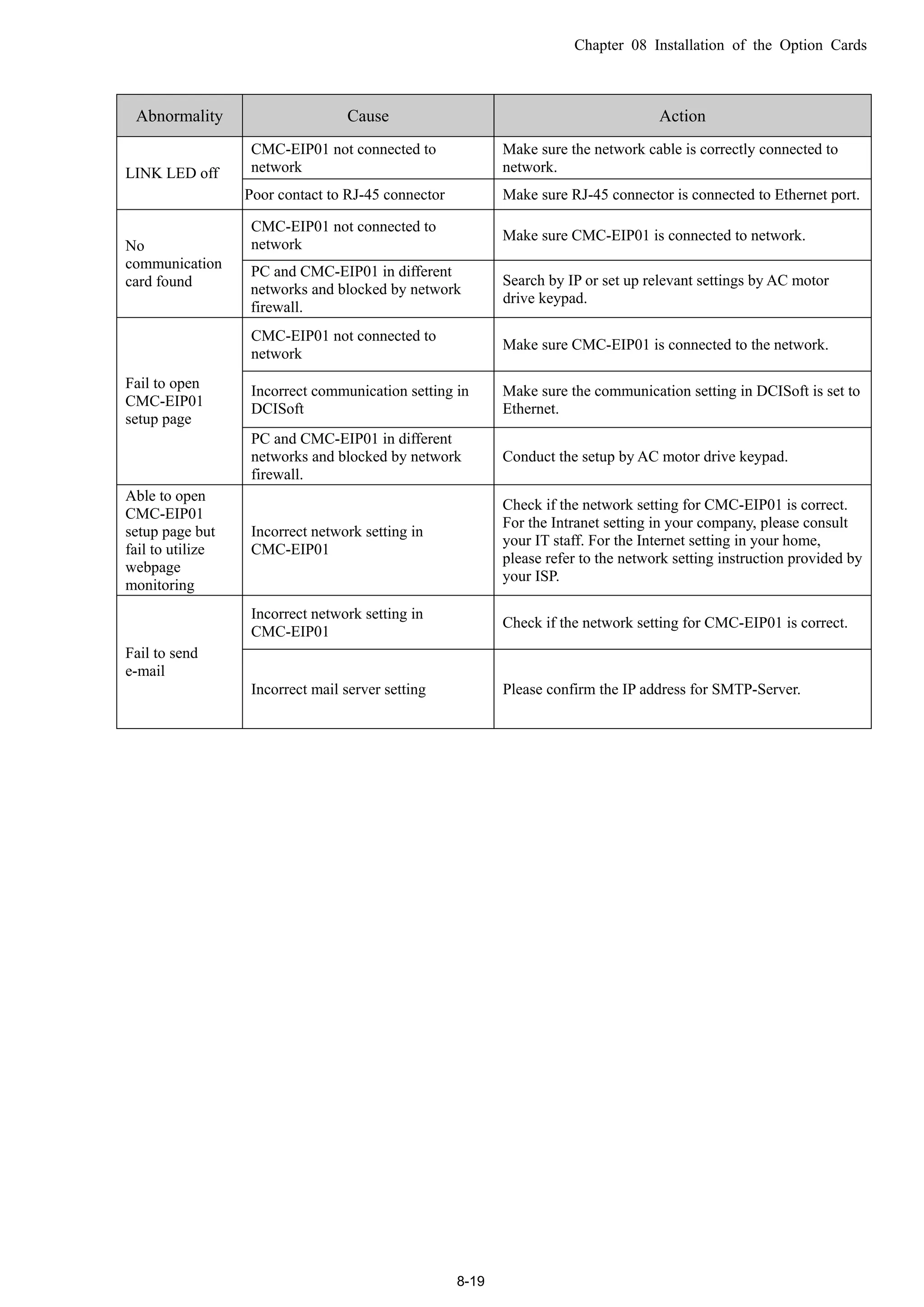
Troubleshooting
Abnormality Cause Action
AC motor drive not powered
Check if AC motor drive is powered, and if the power
supply is normal.POWER LED
off CMC-EIP01 not connected to AC
motor drive
Make sure CMC-EIP01 is connected to AC motor drive.](https://image.slidesharecdn.com/deltacp2000men20120331-140612232906-phpapp02/75/Delta-cp2000-m_en_20120331-131-2048.jpg)


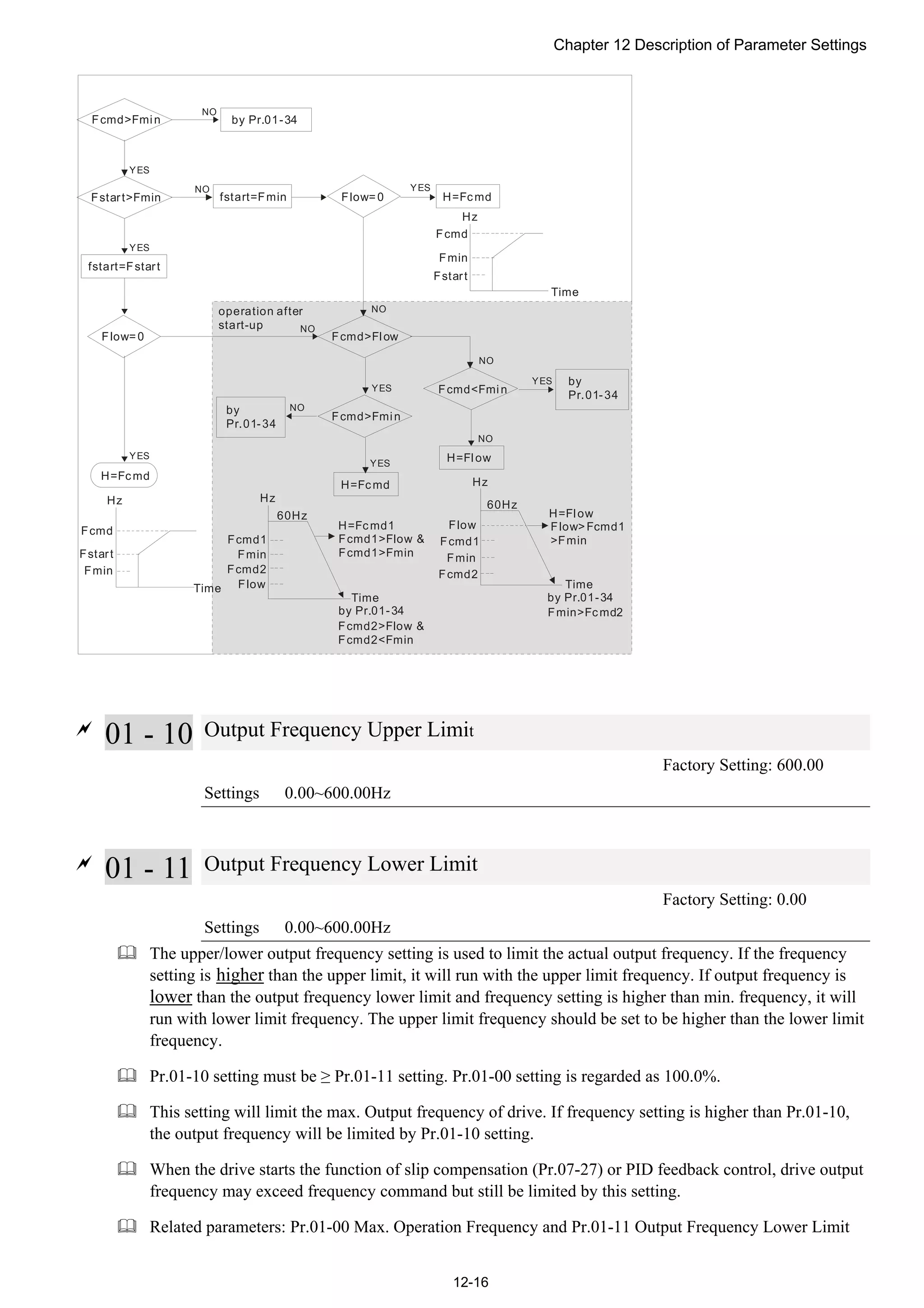
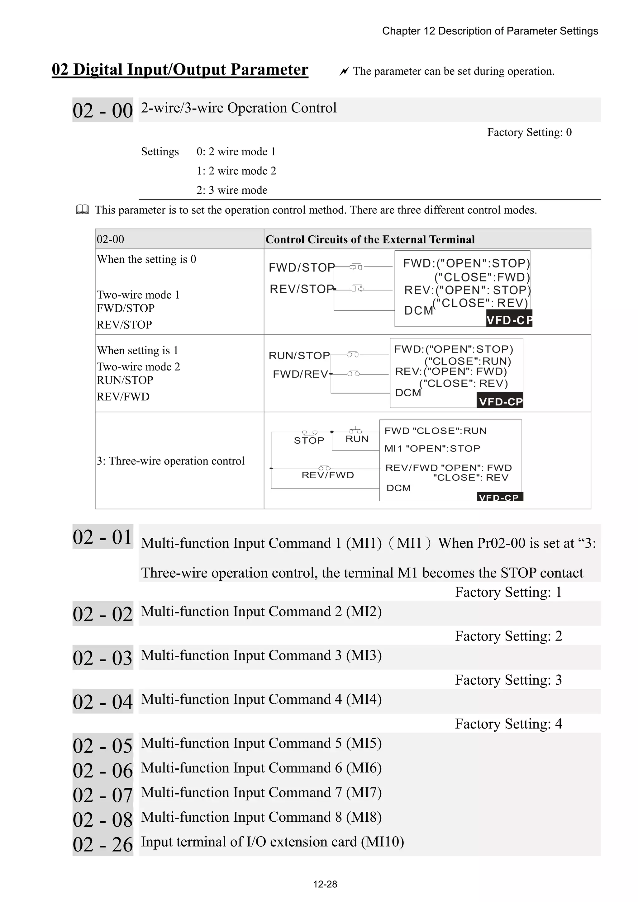
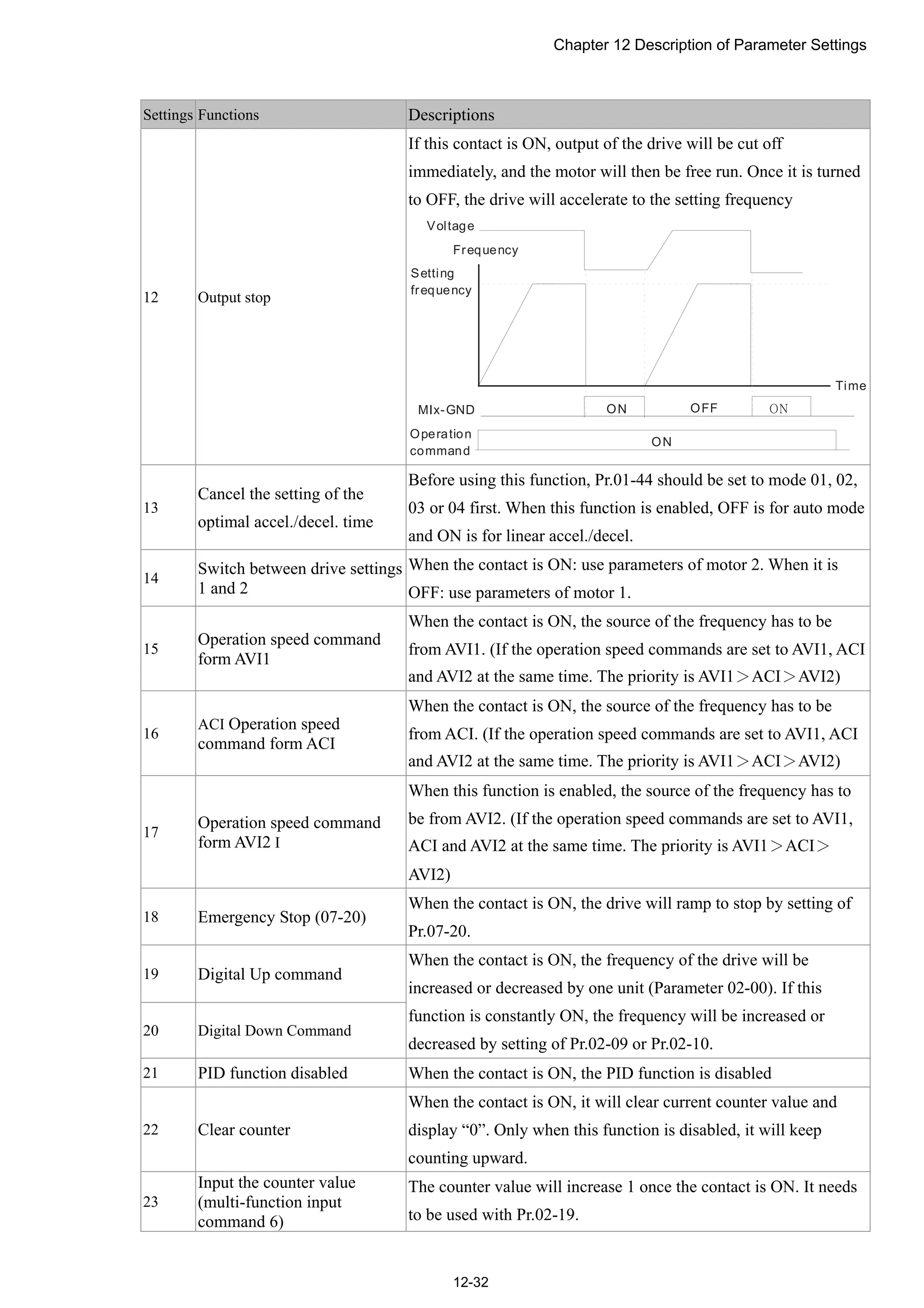
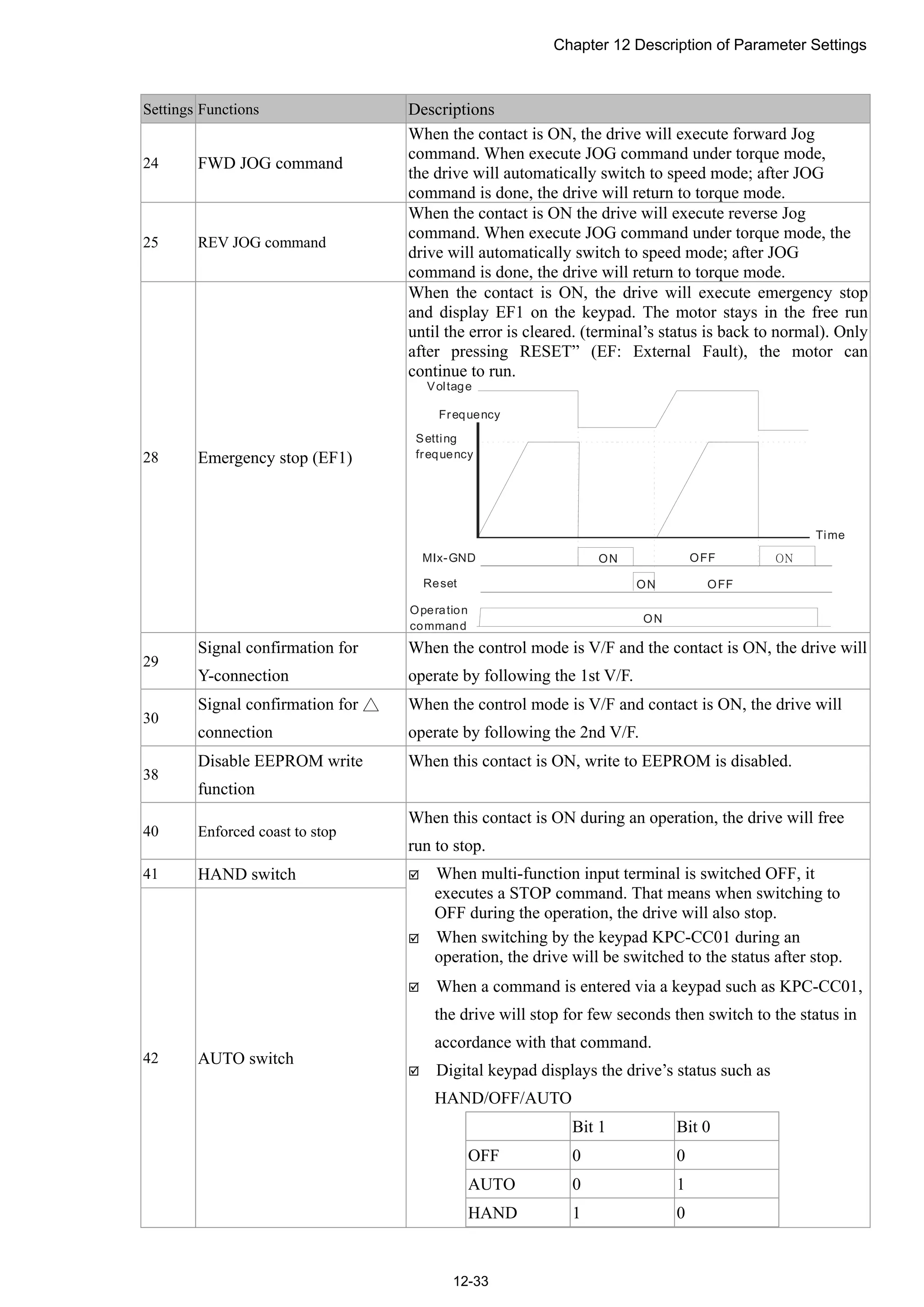
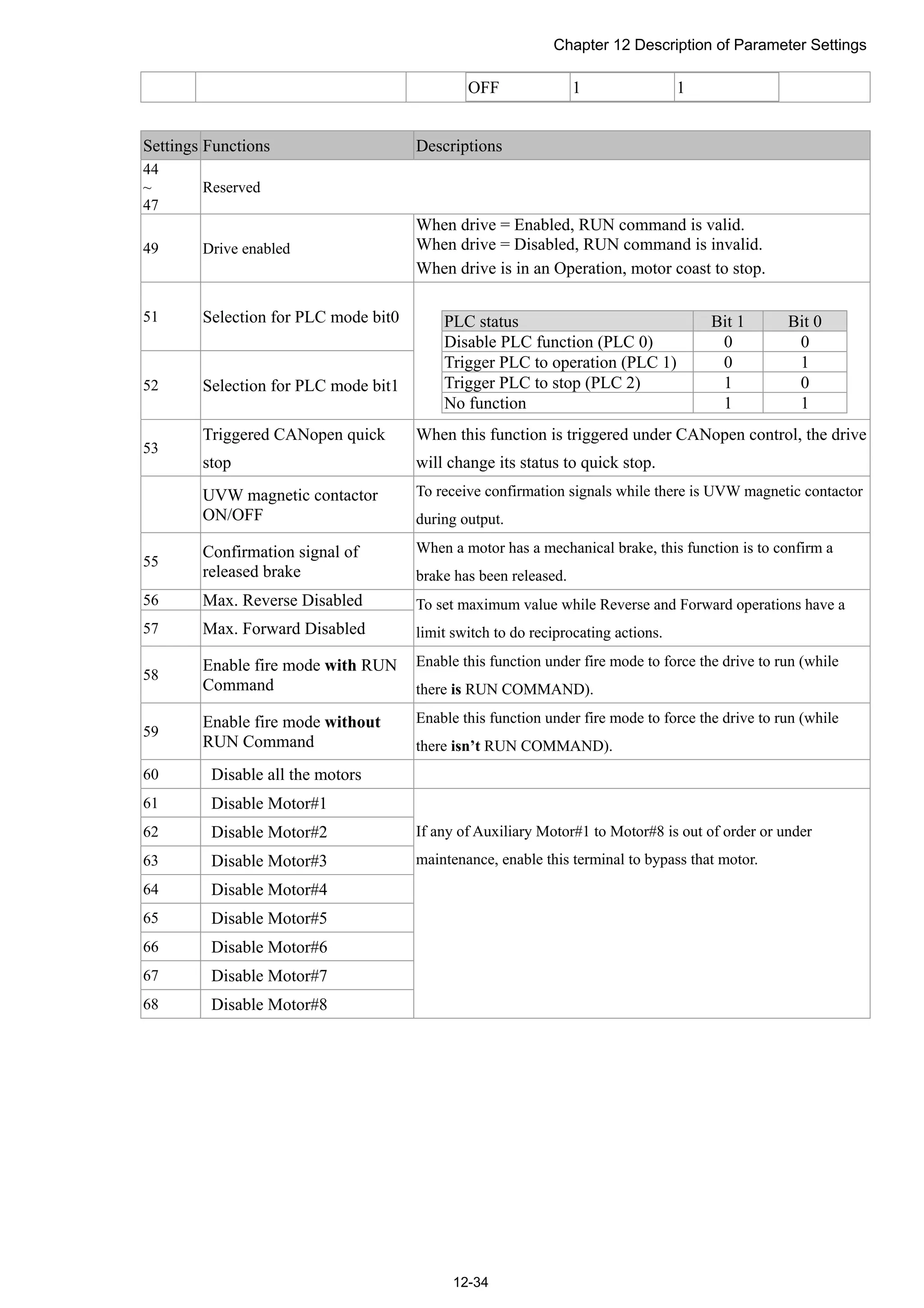
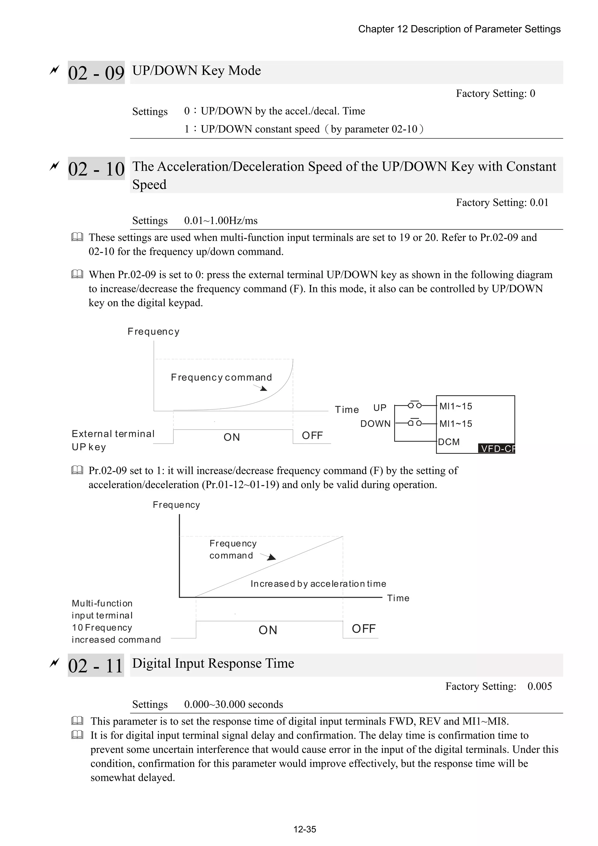
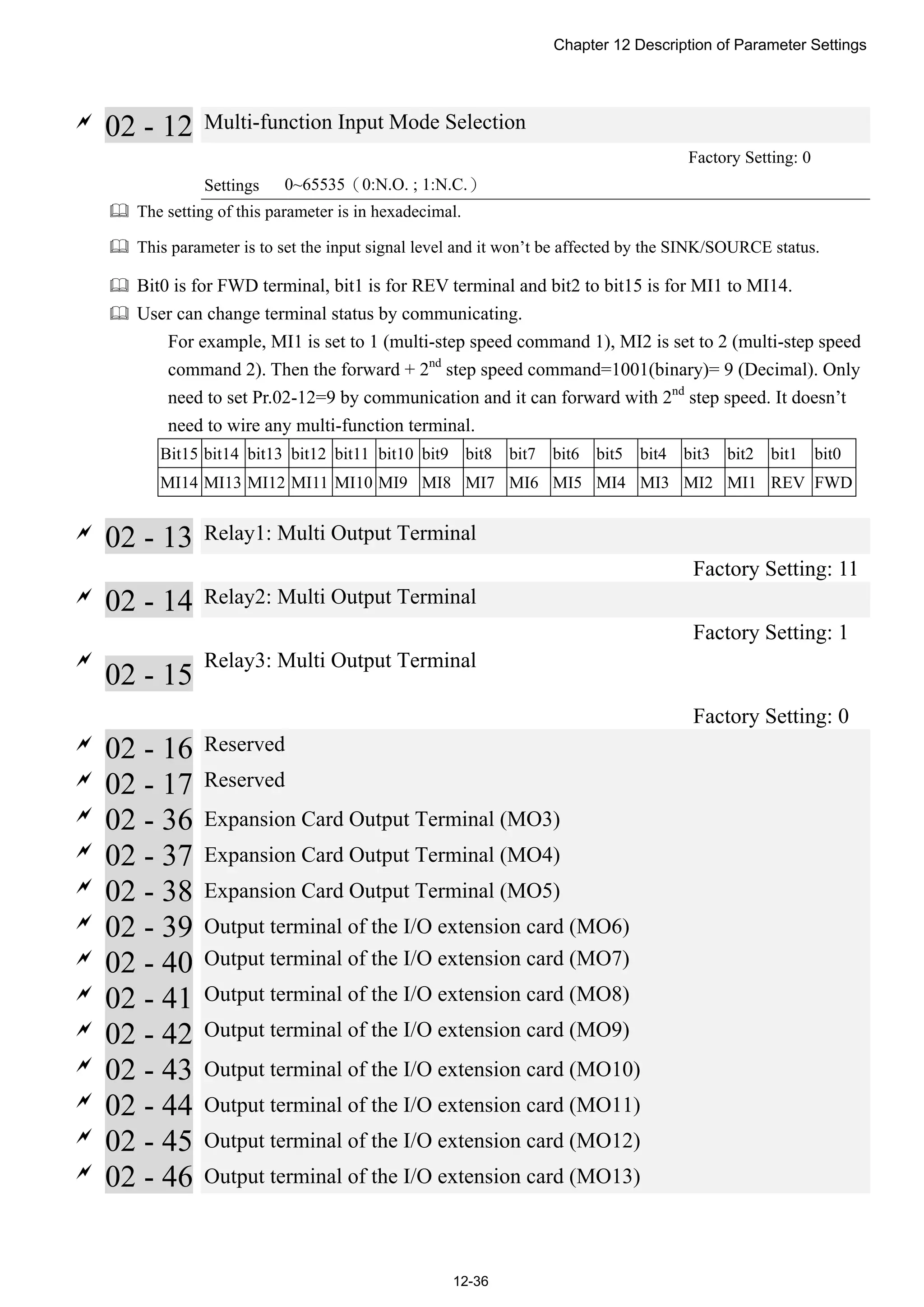
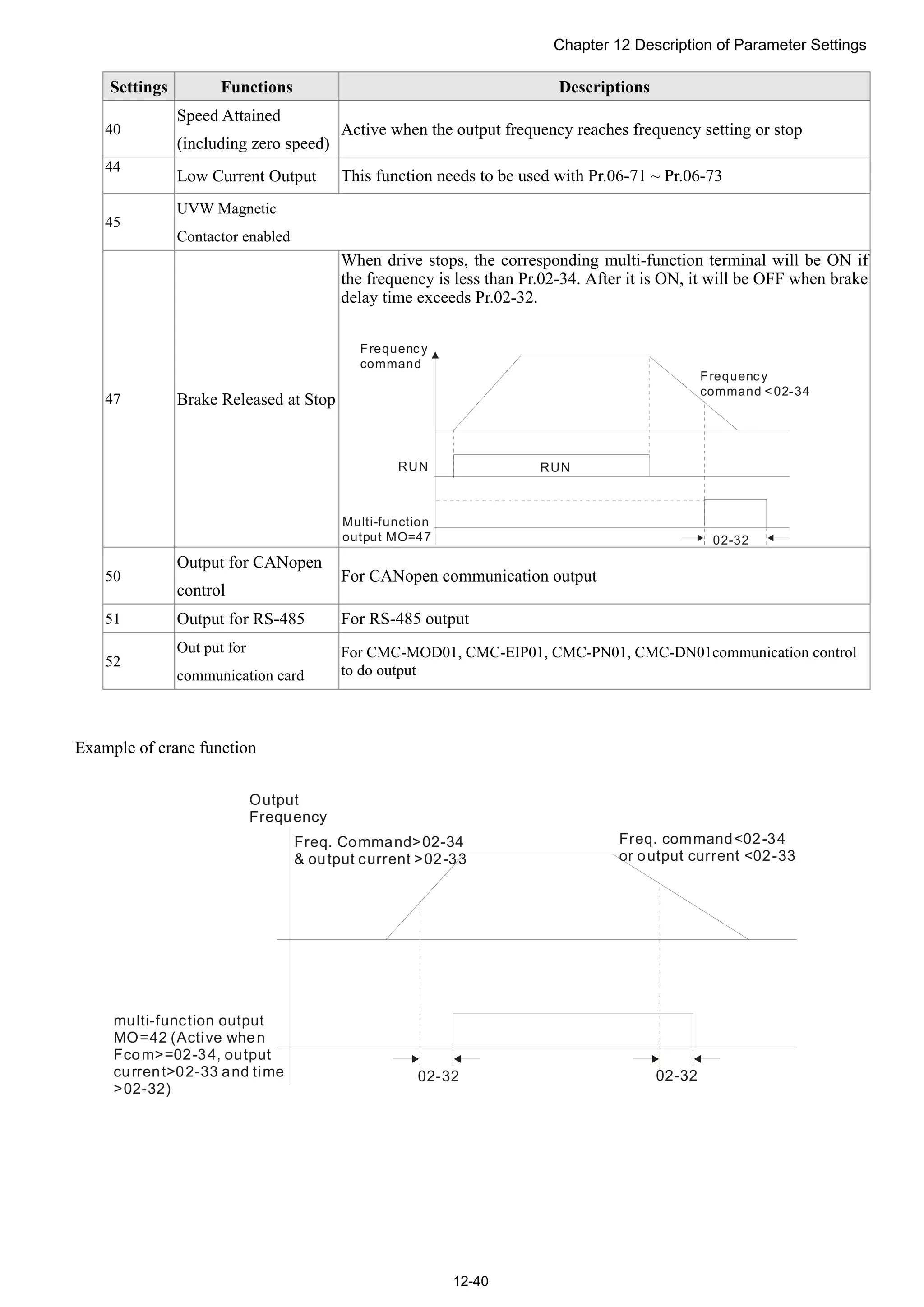
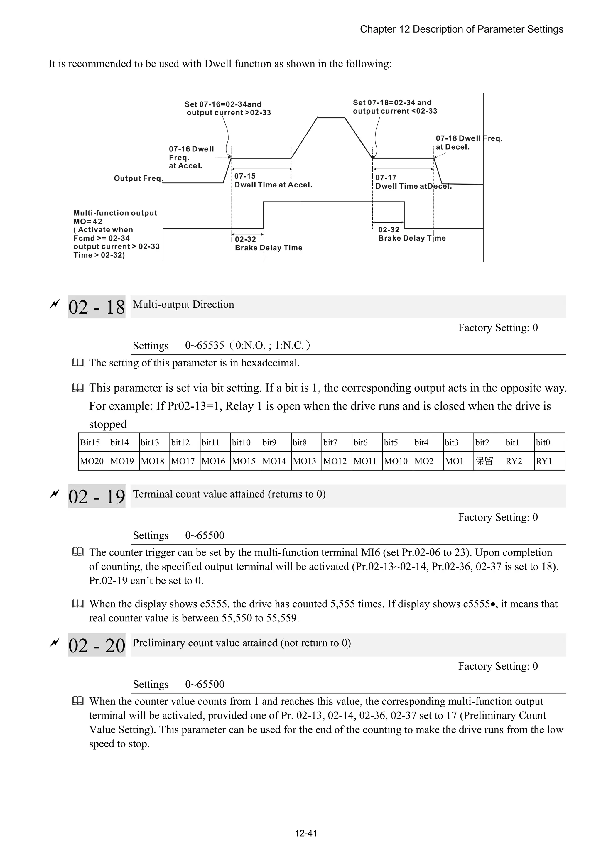
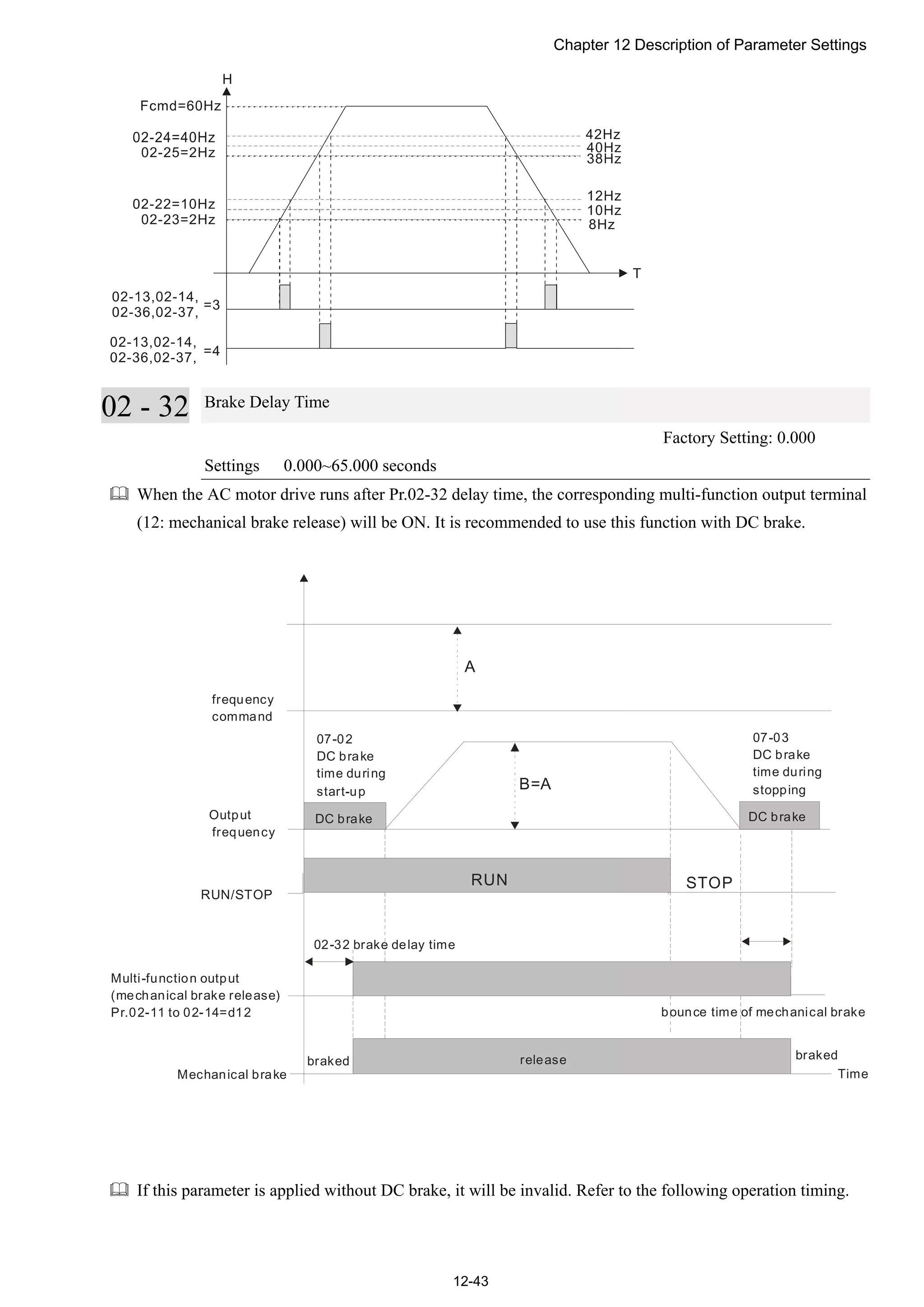
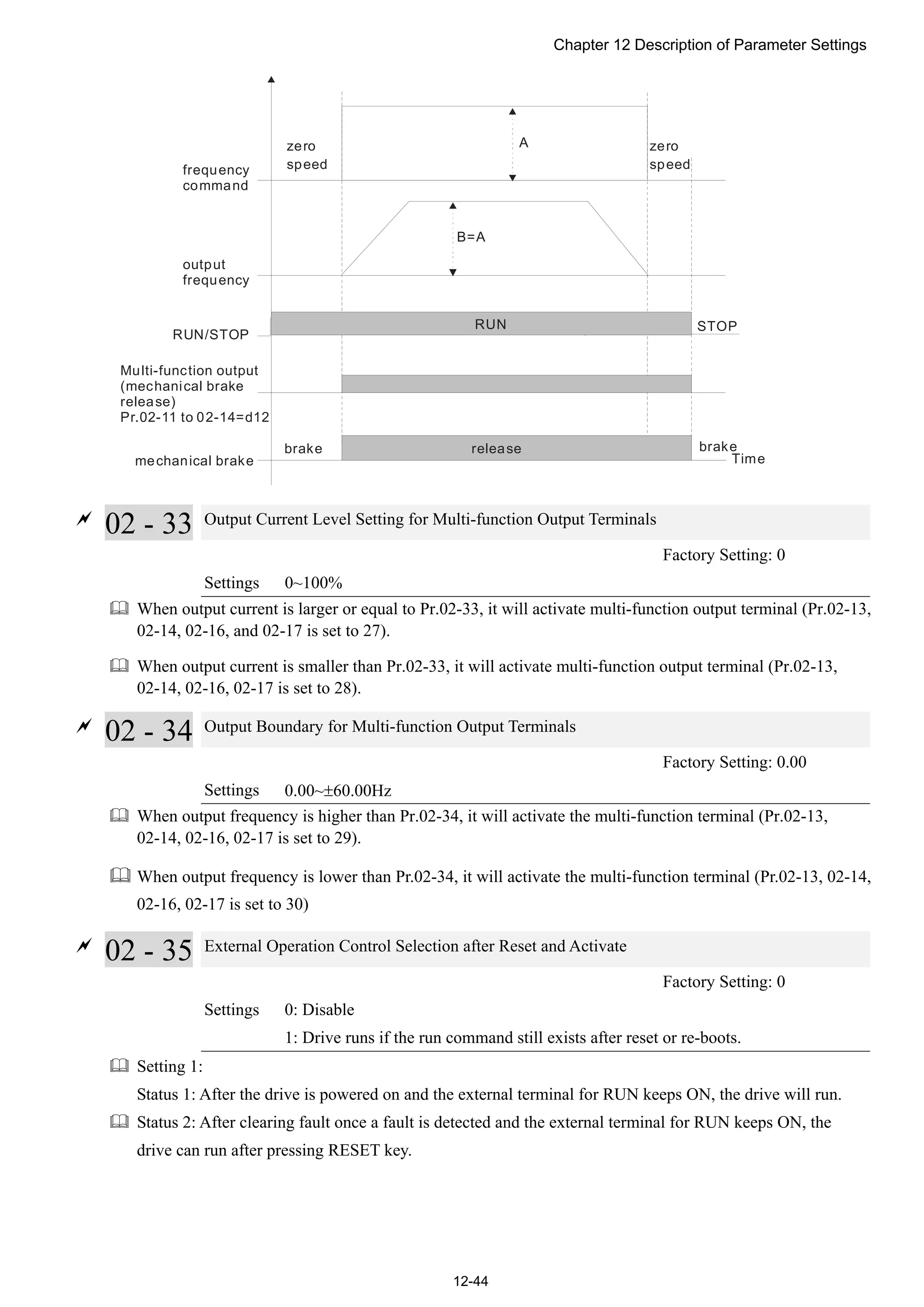
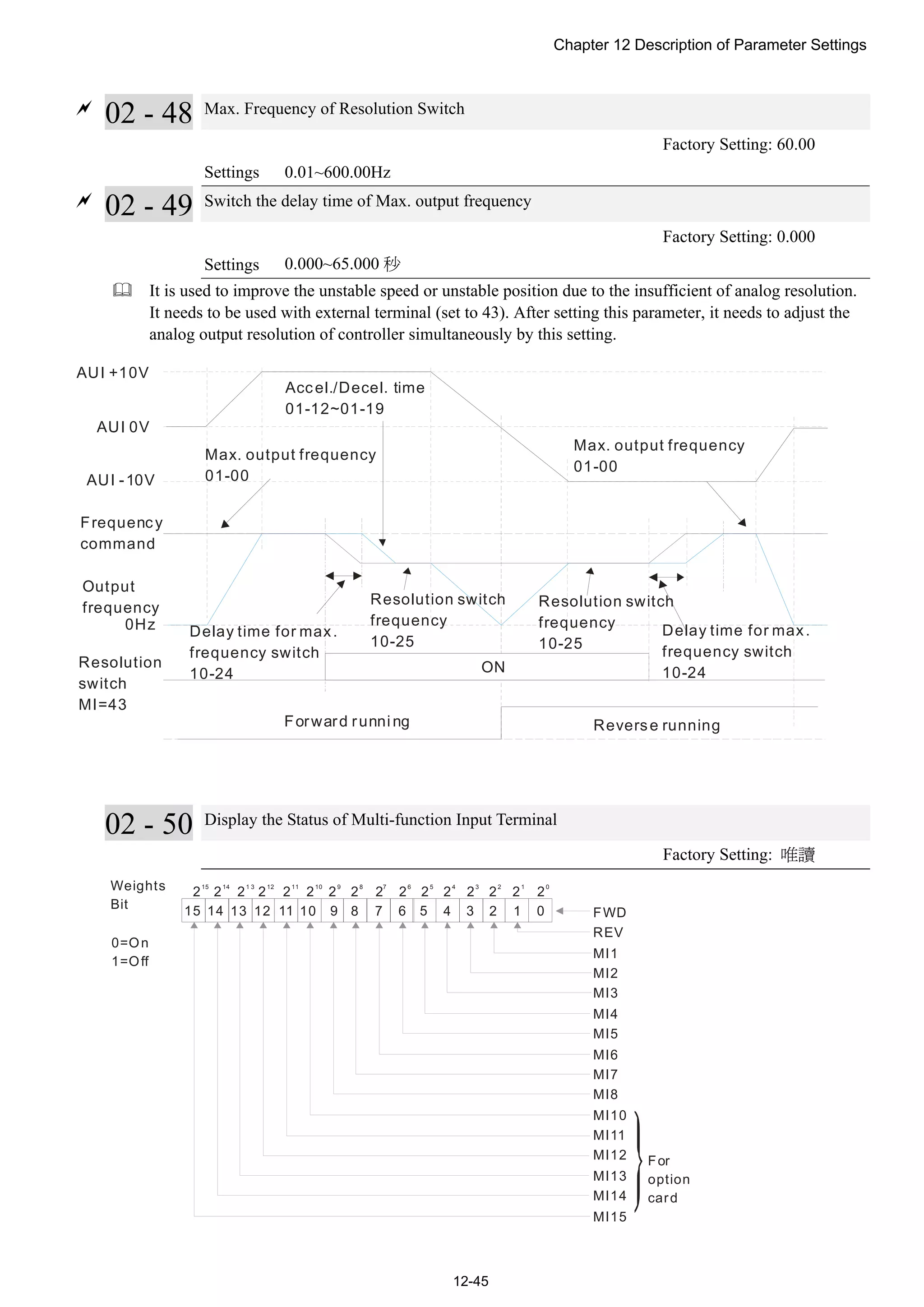
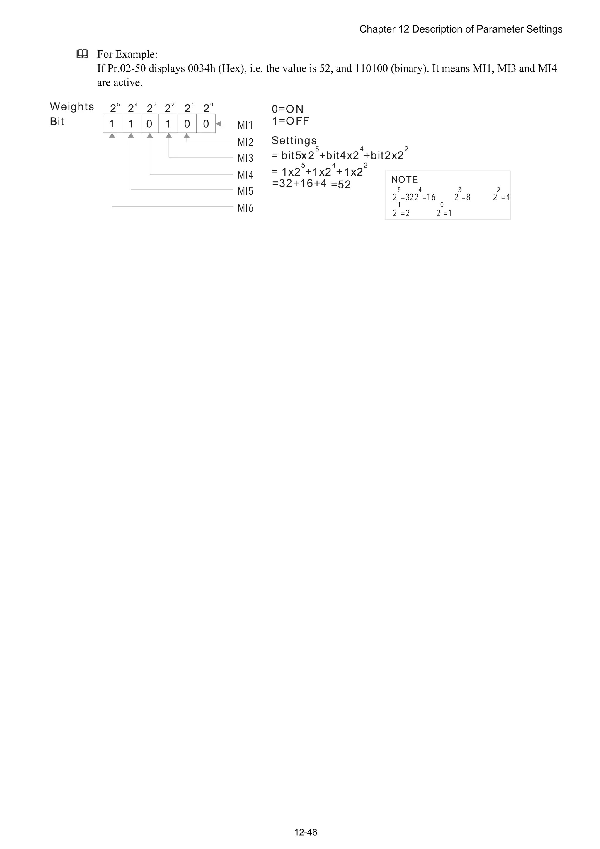
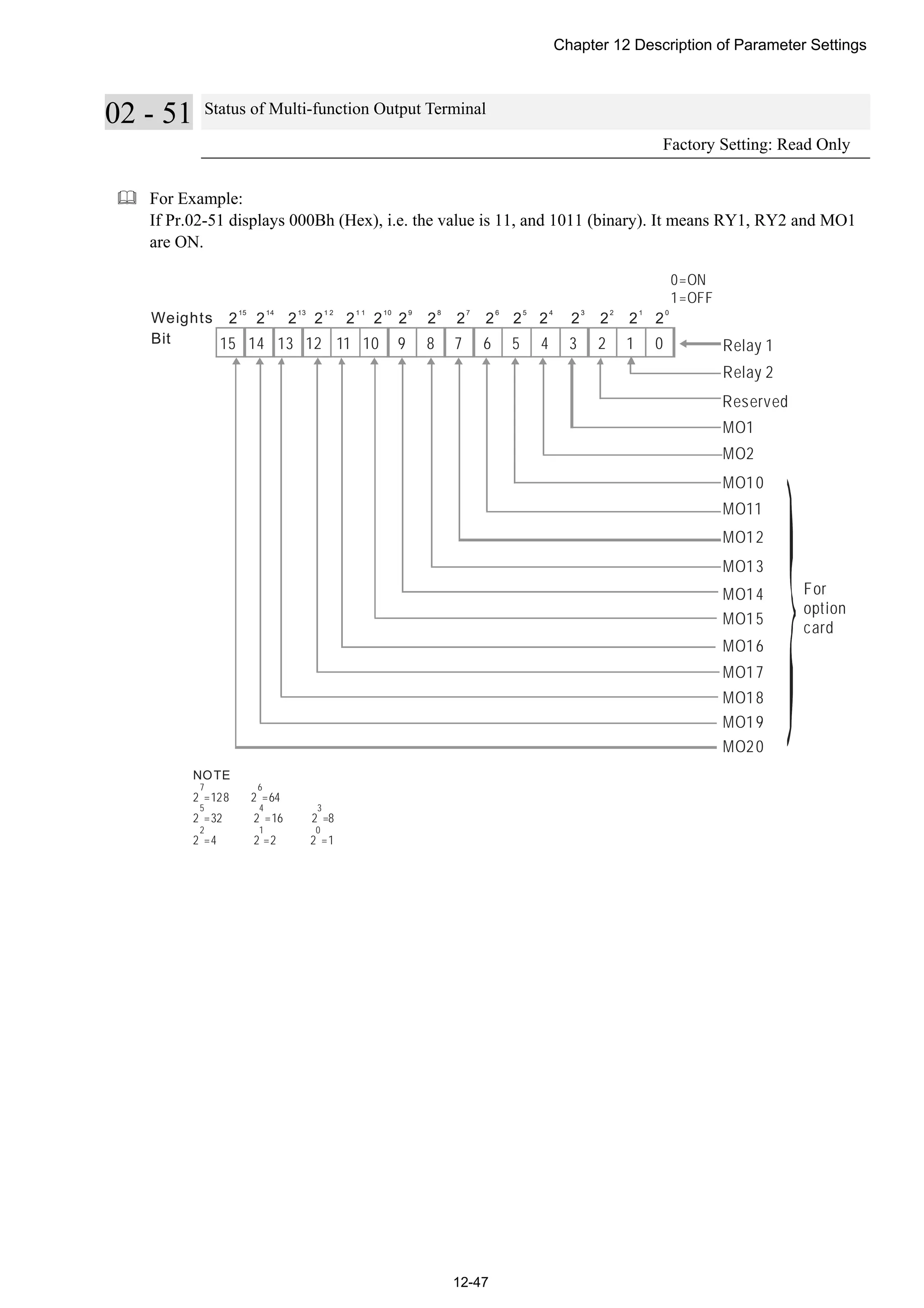
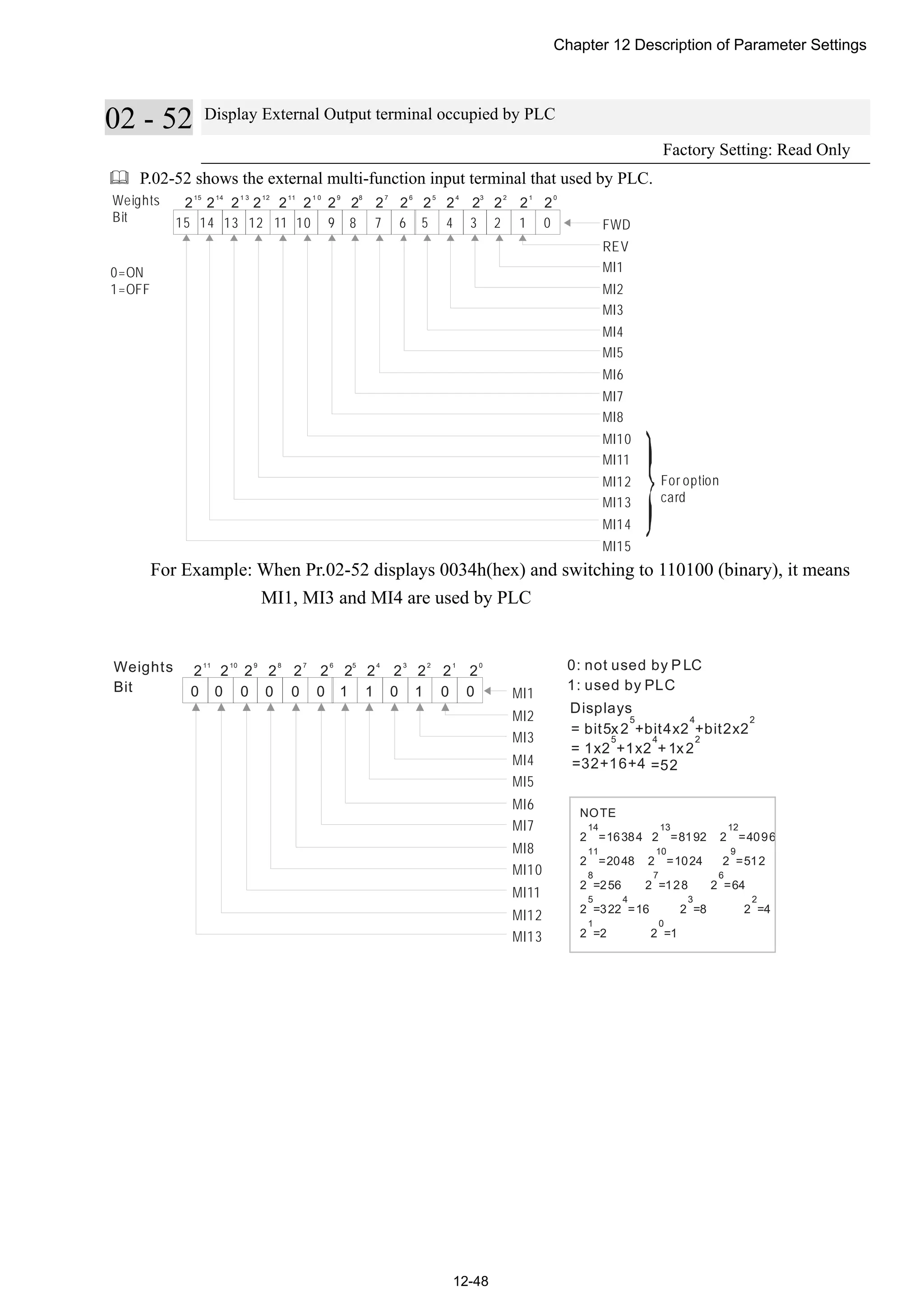
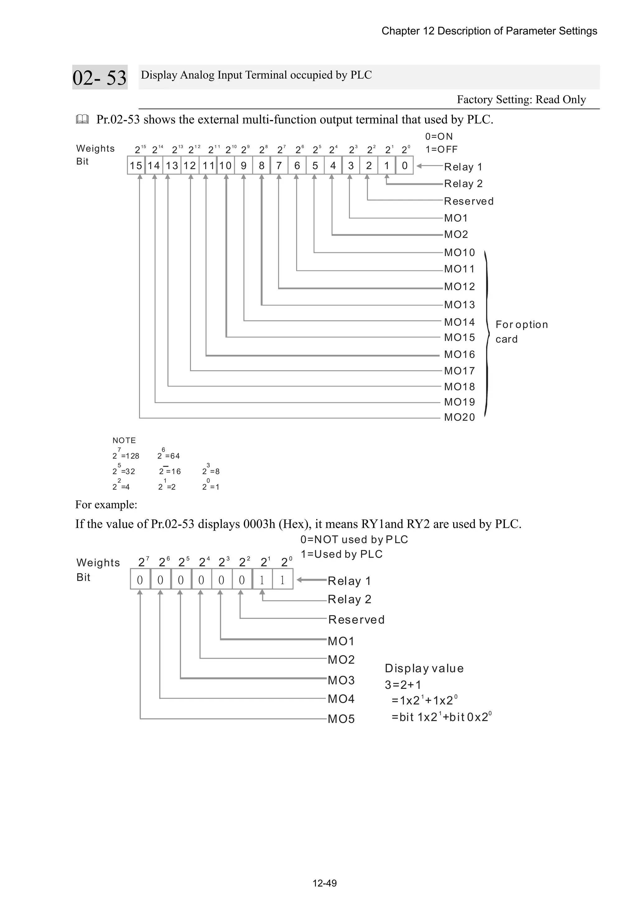
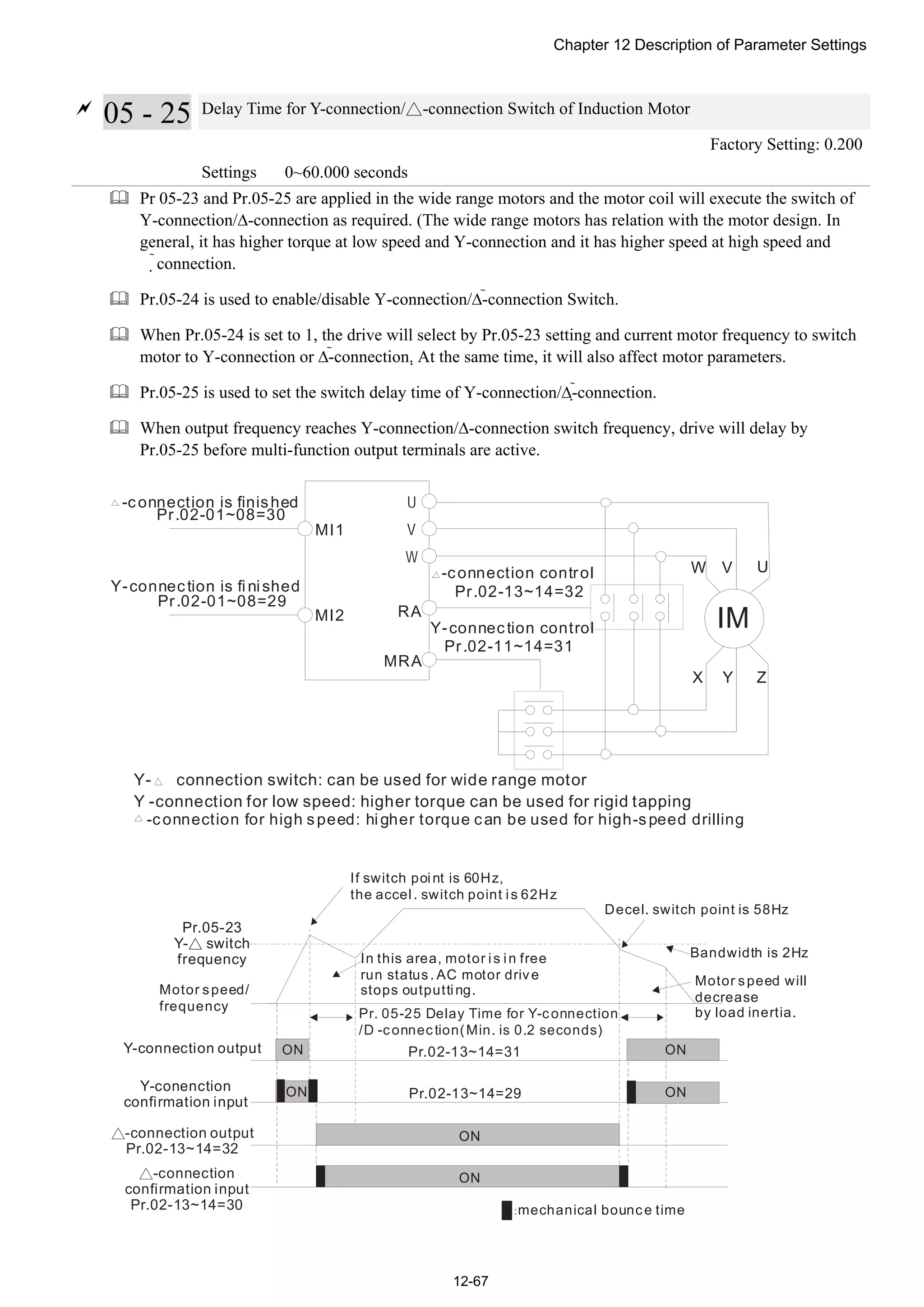
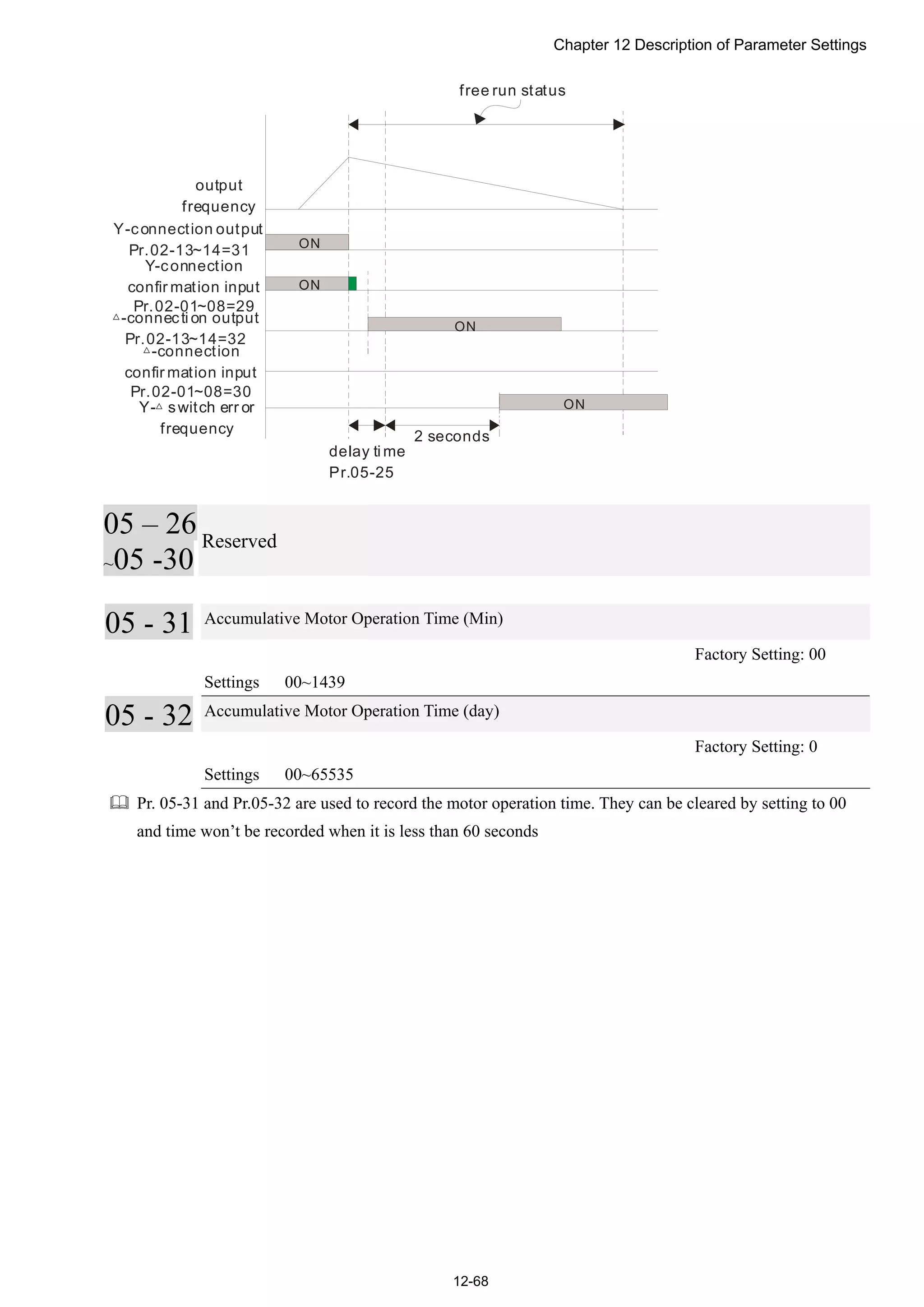
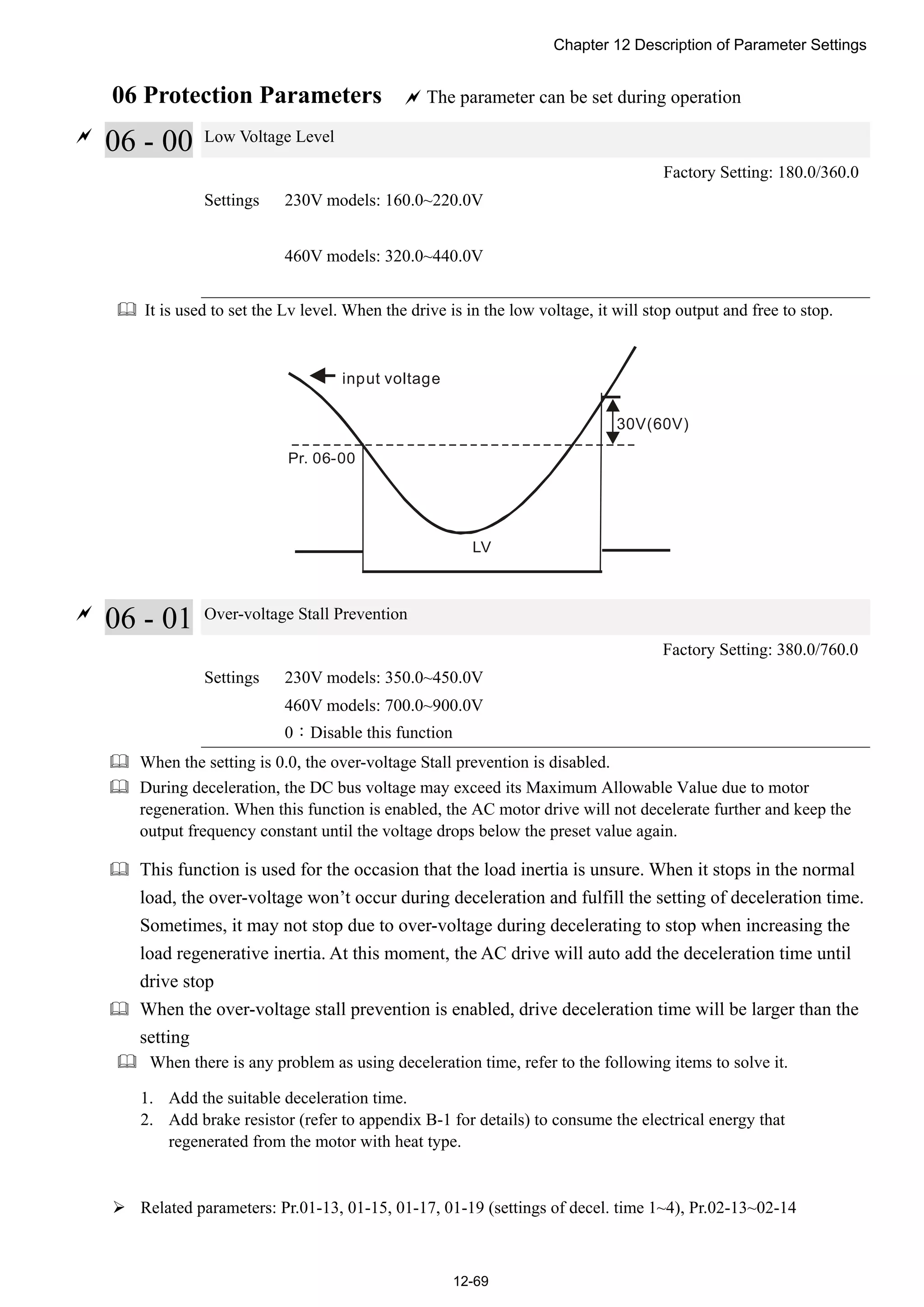
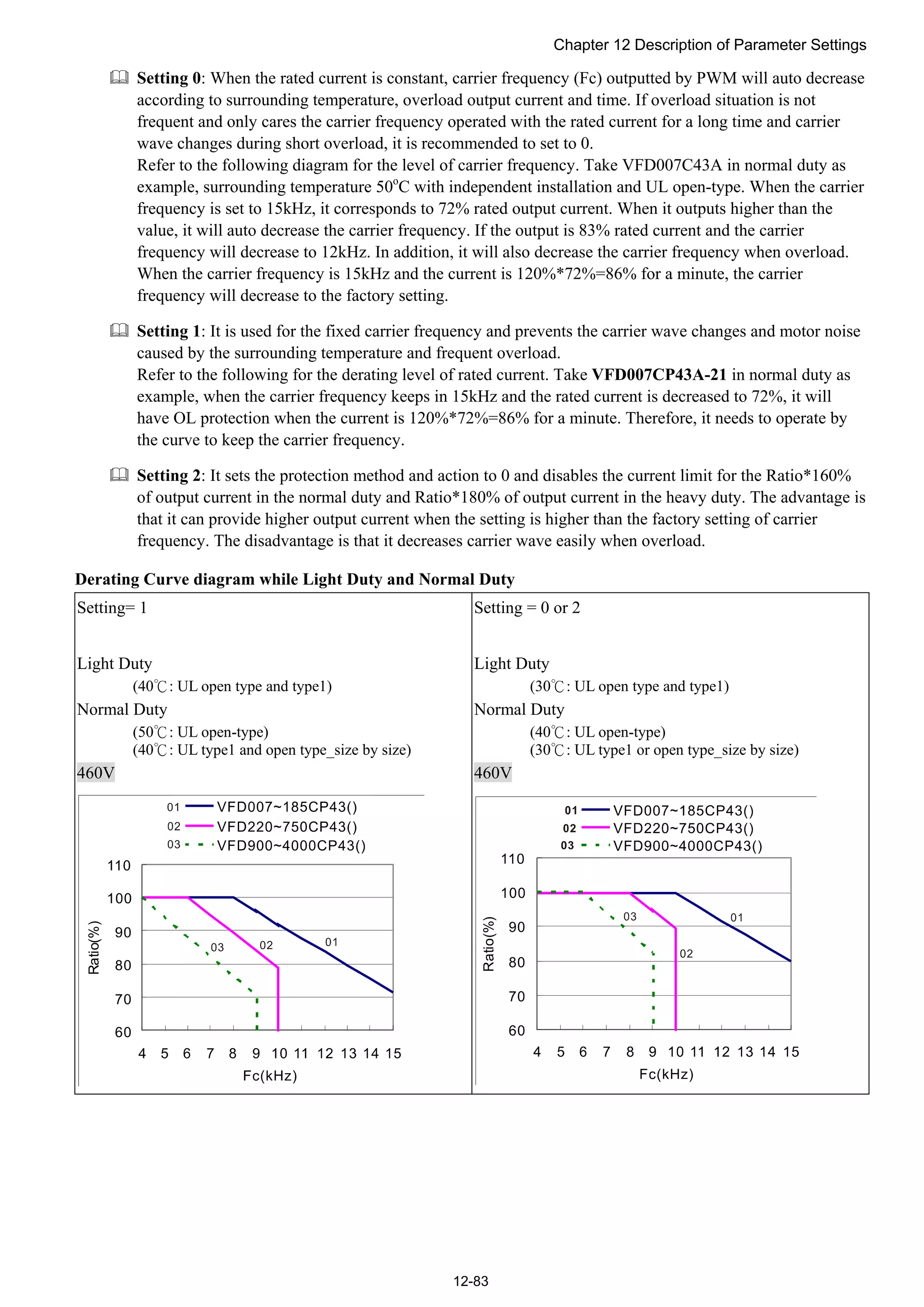
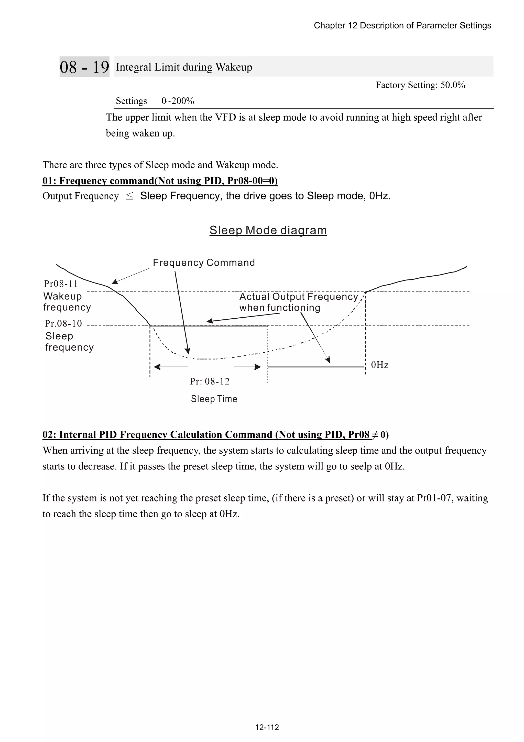
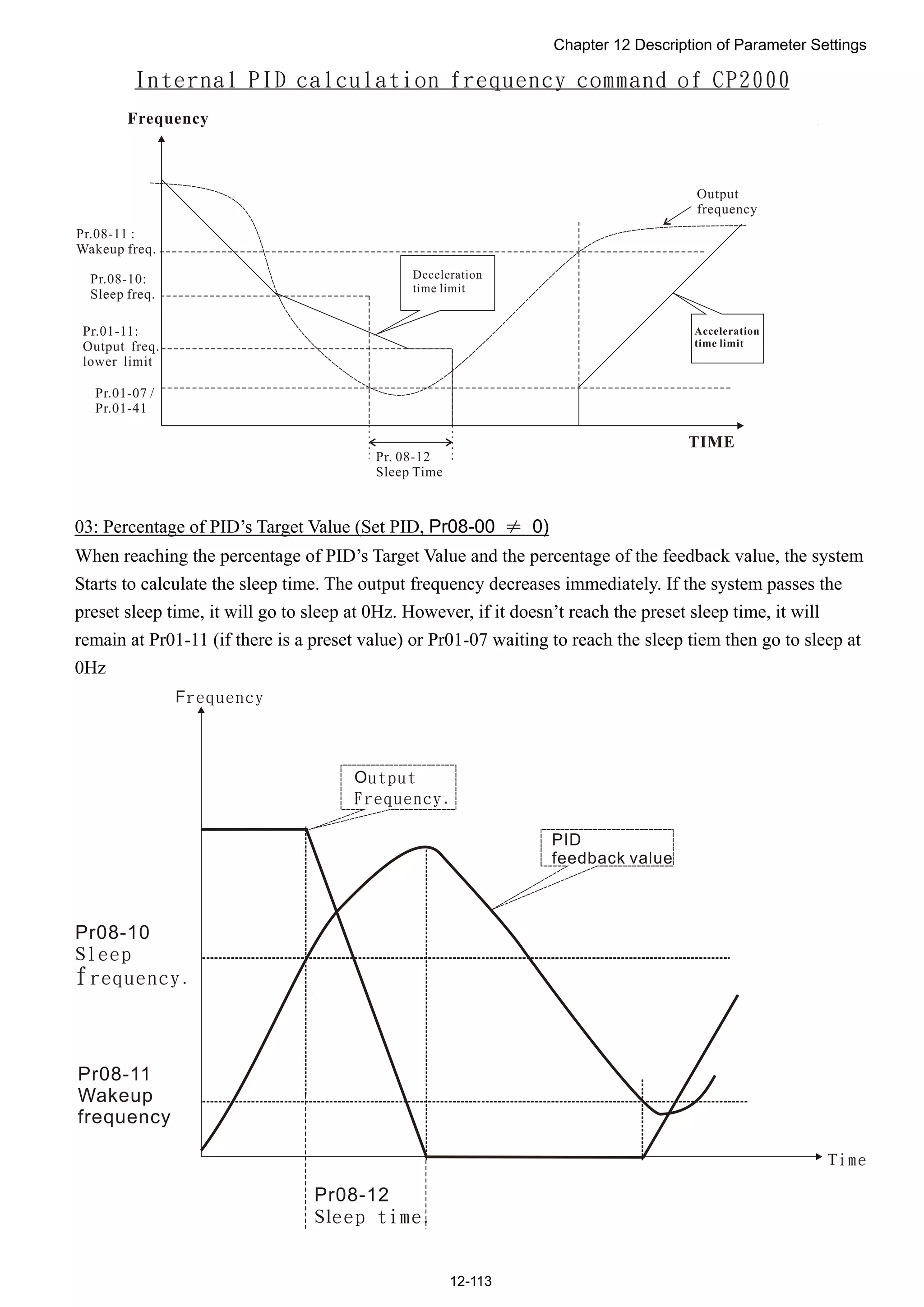
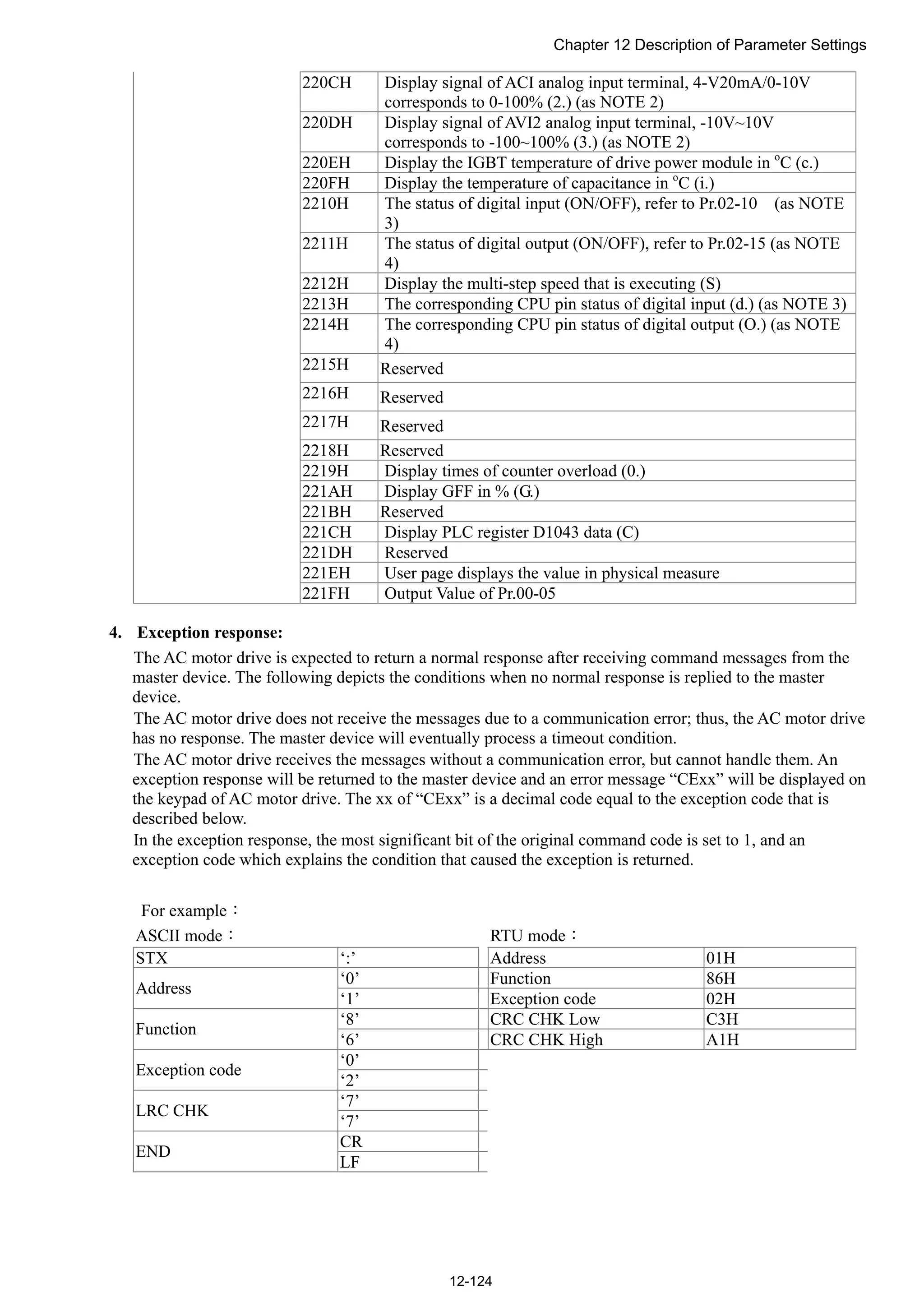
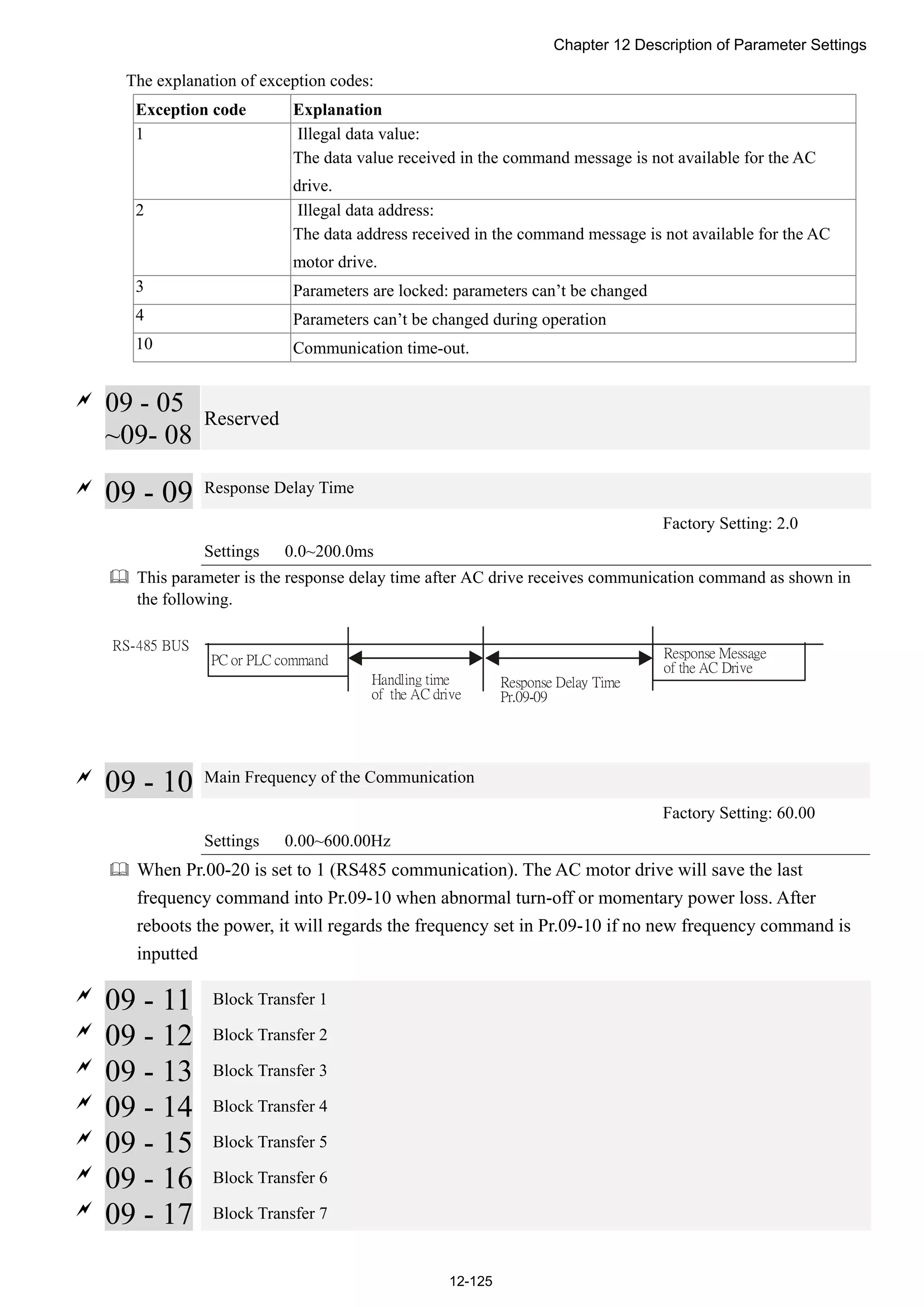
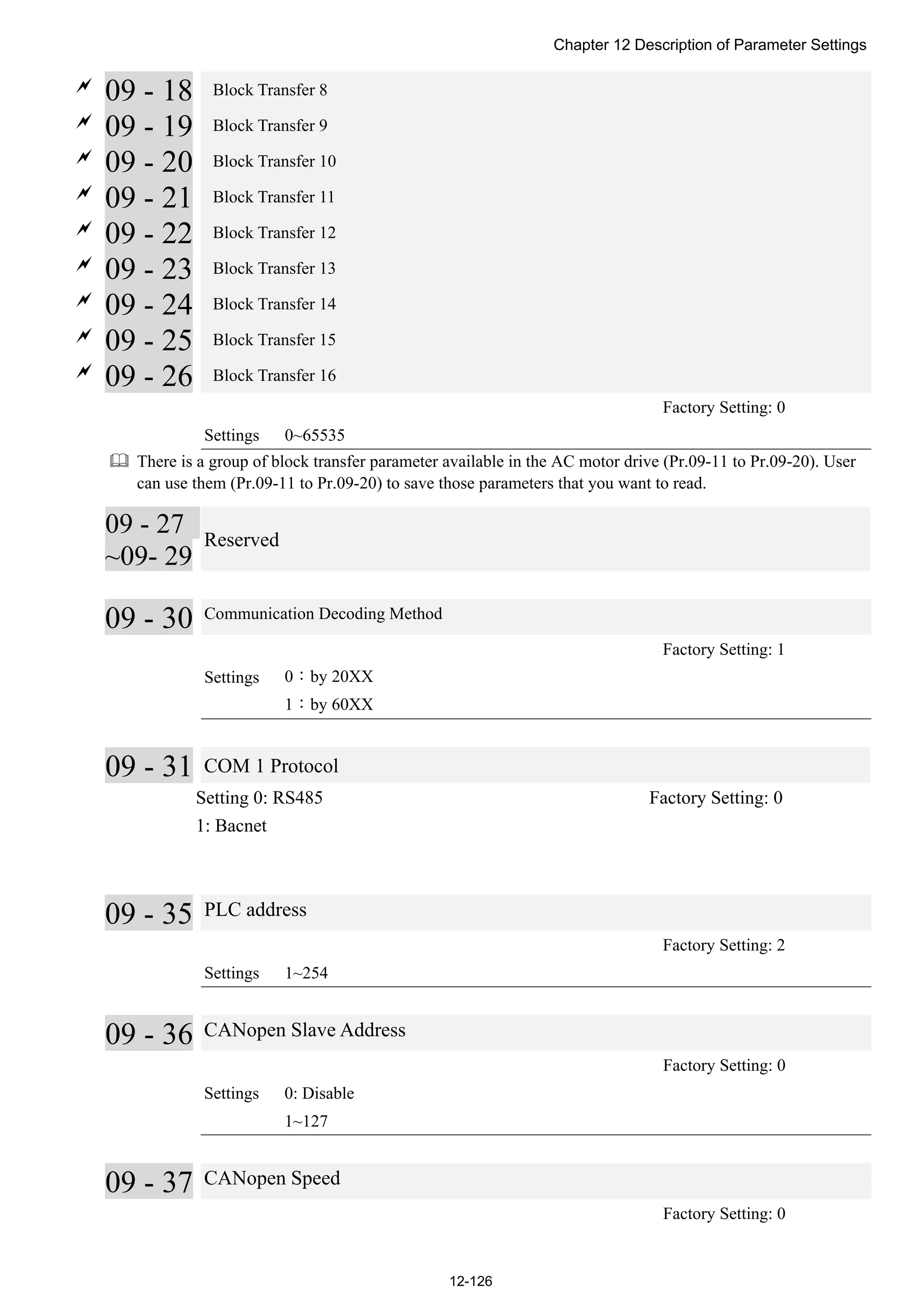
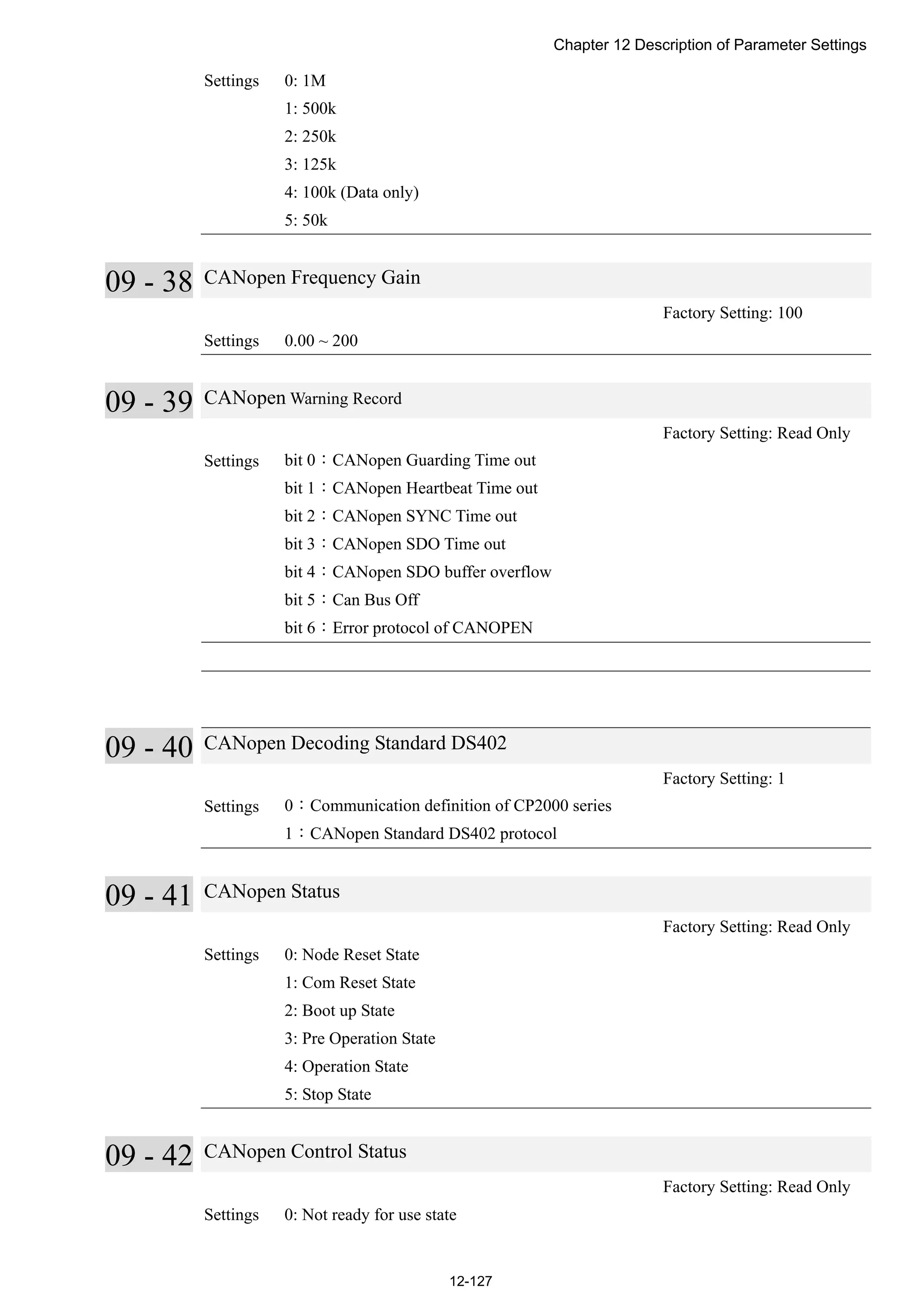
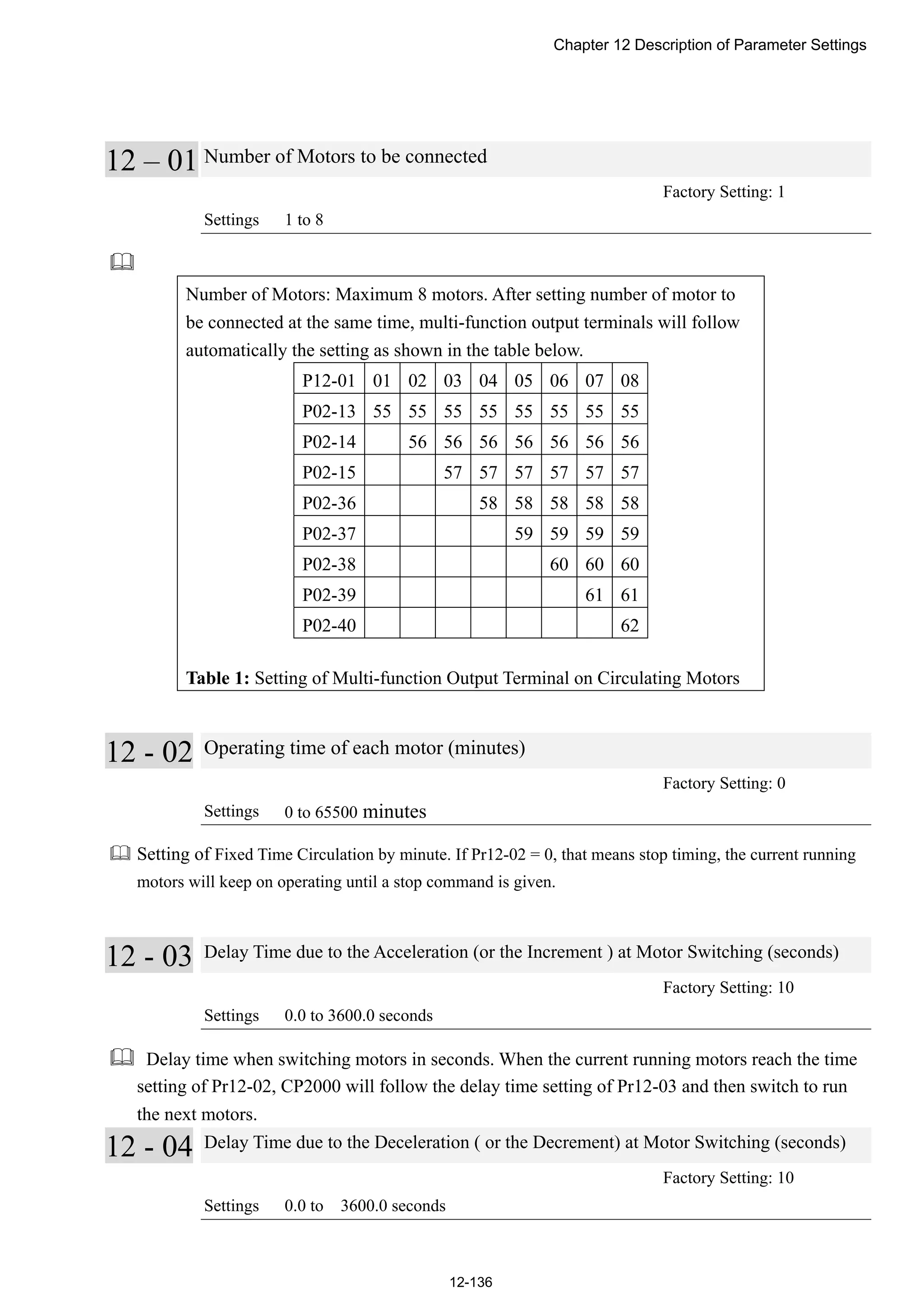
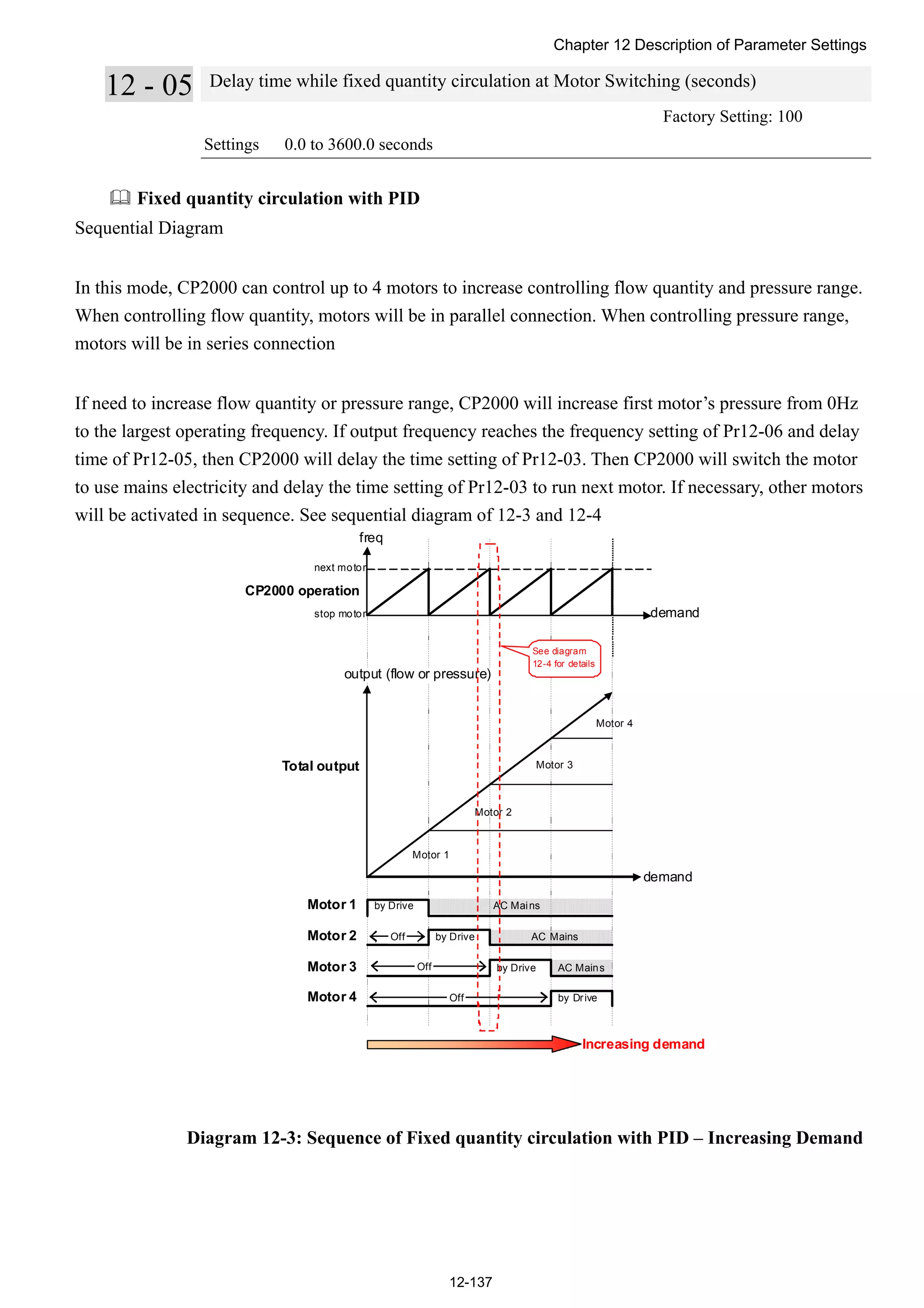
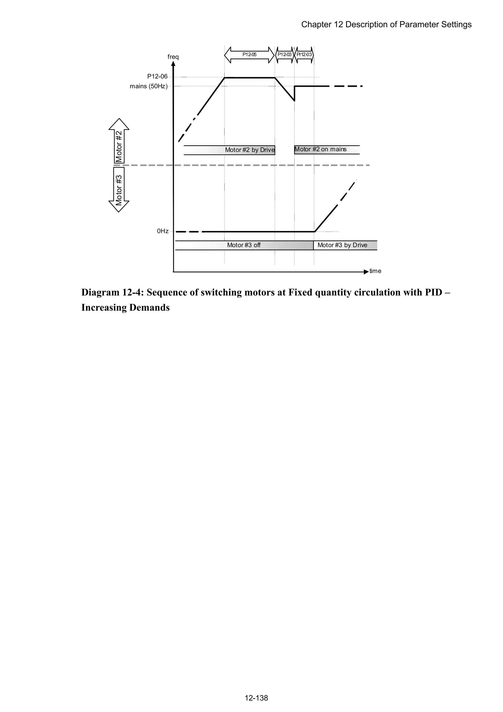
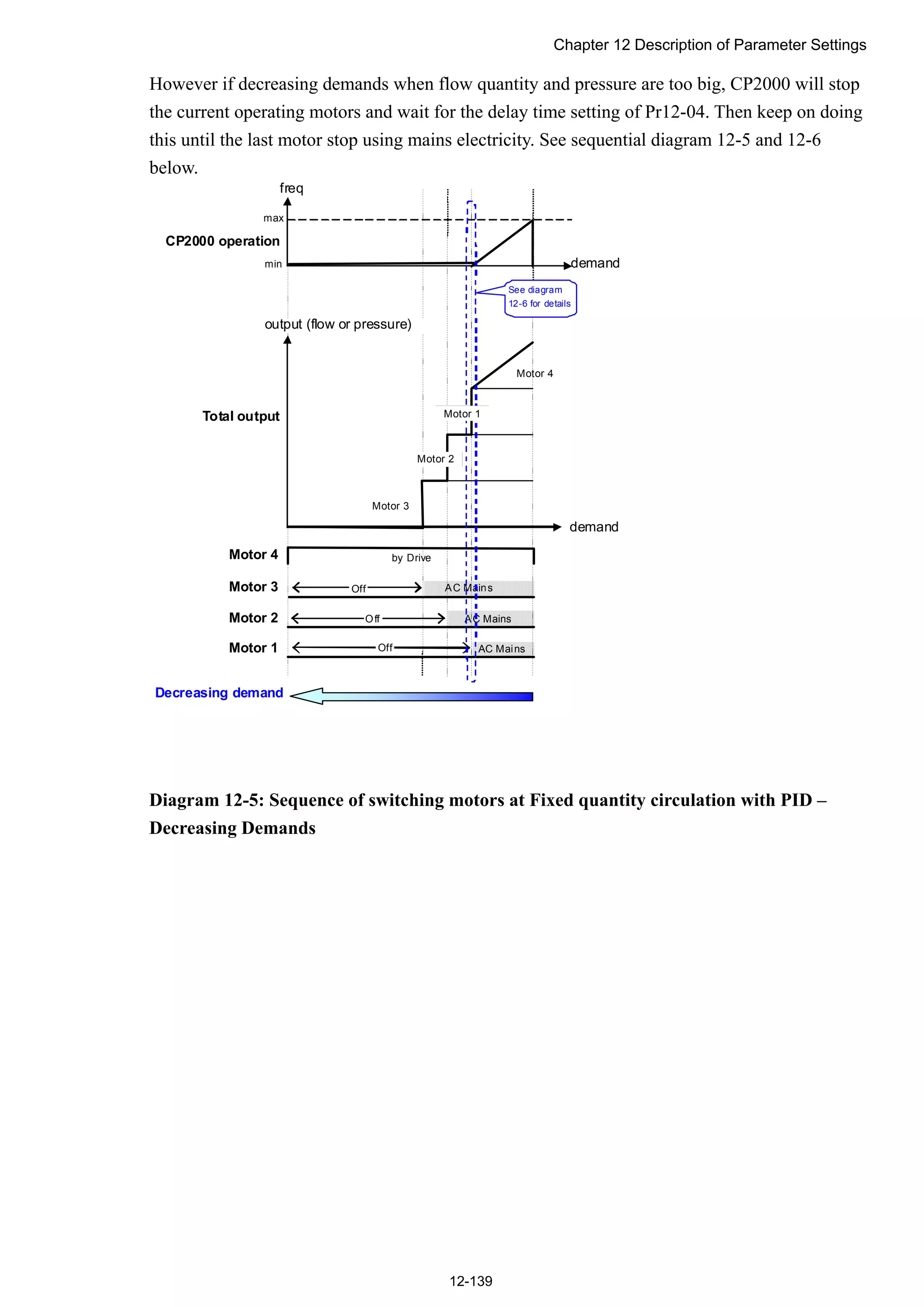
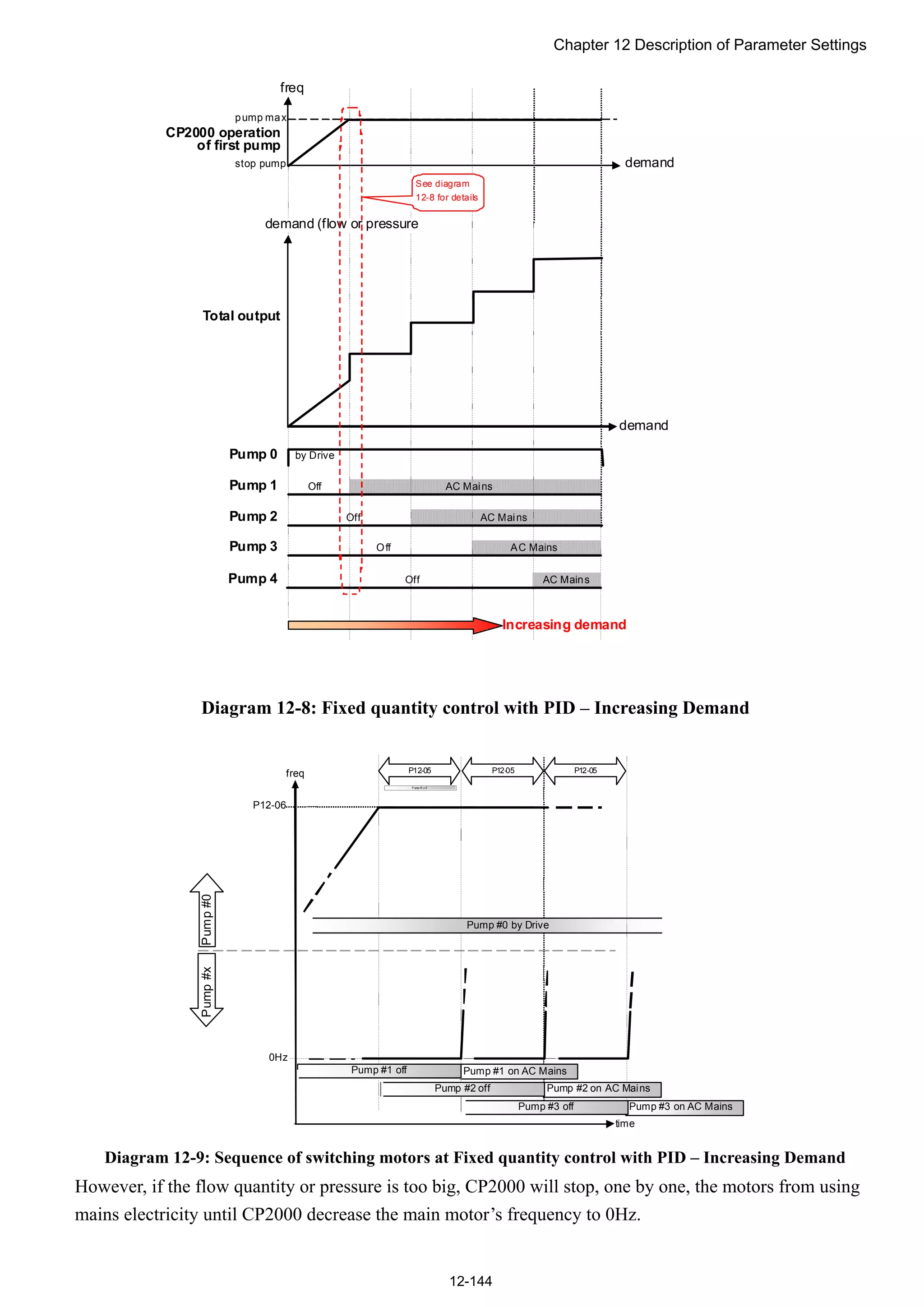
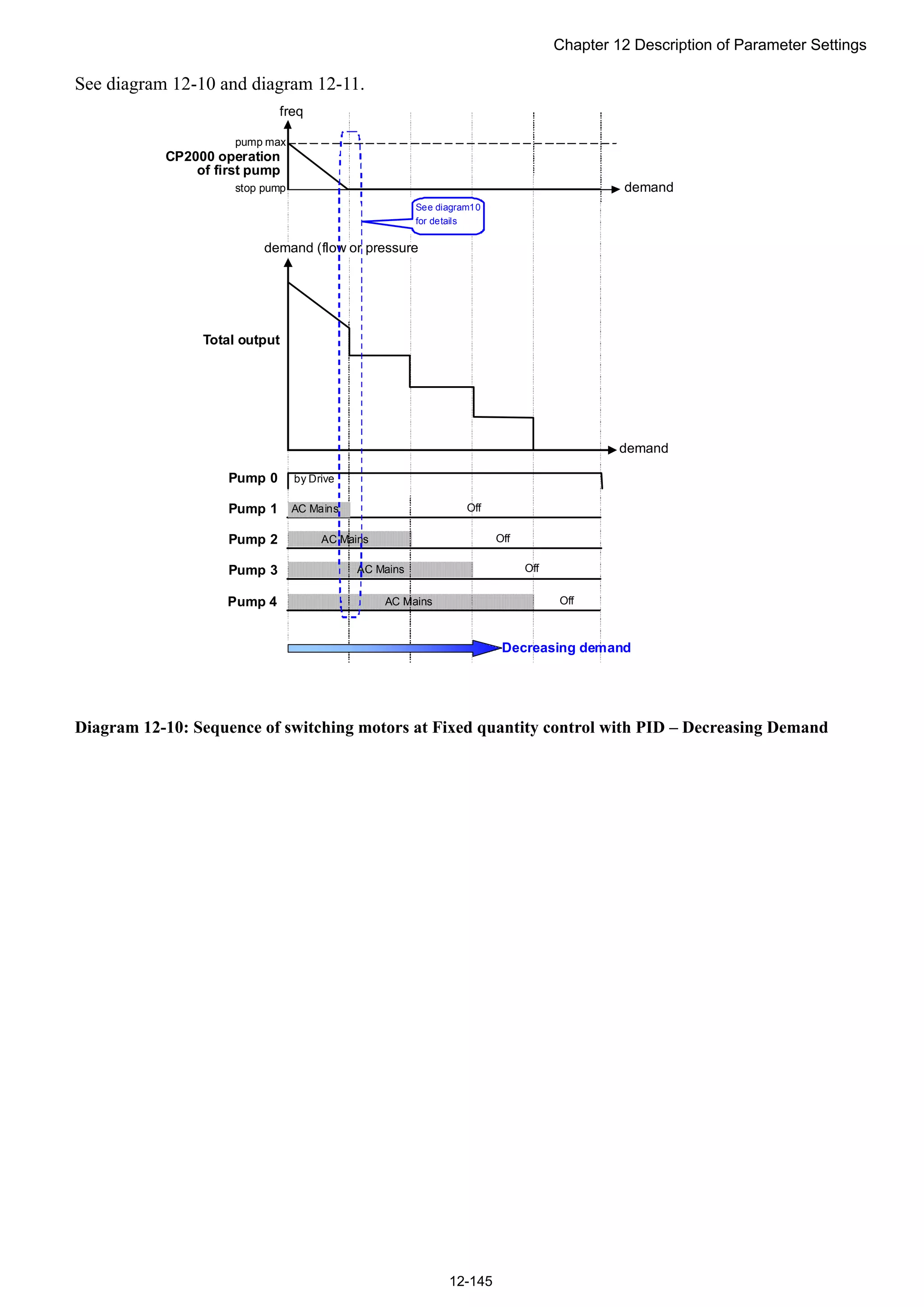
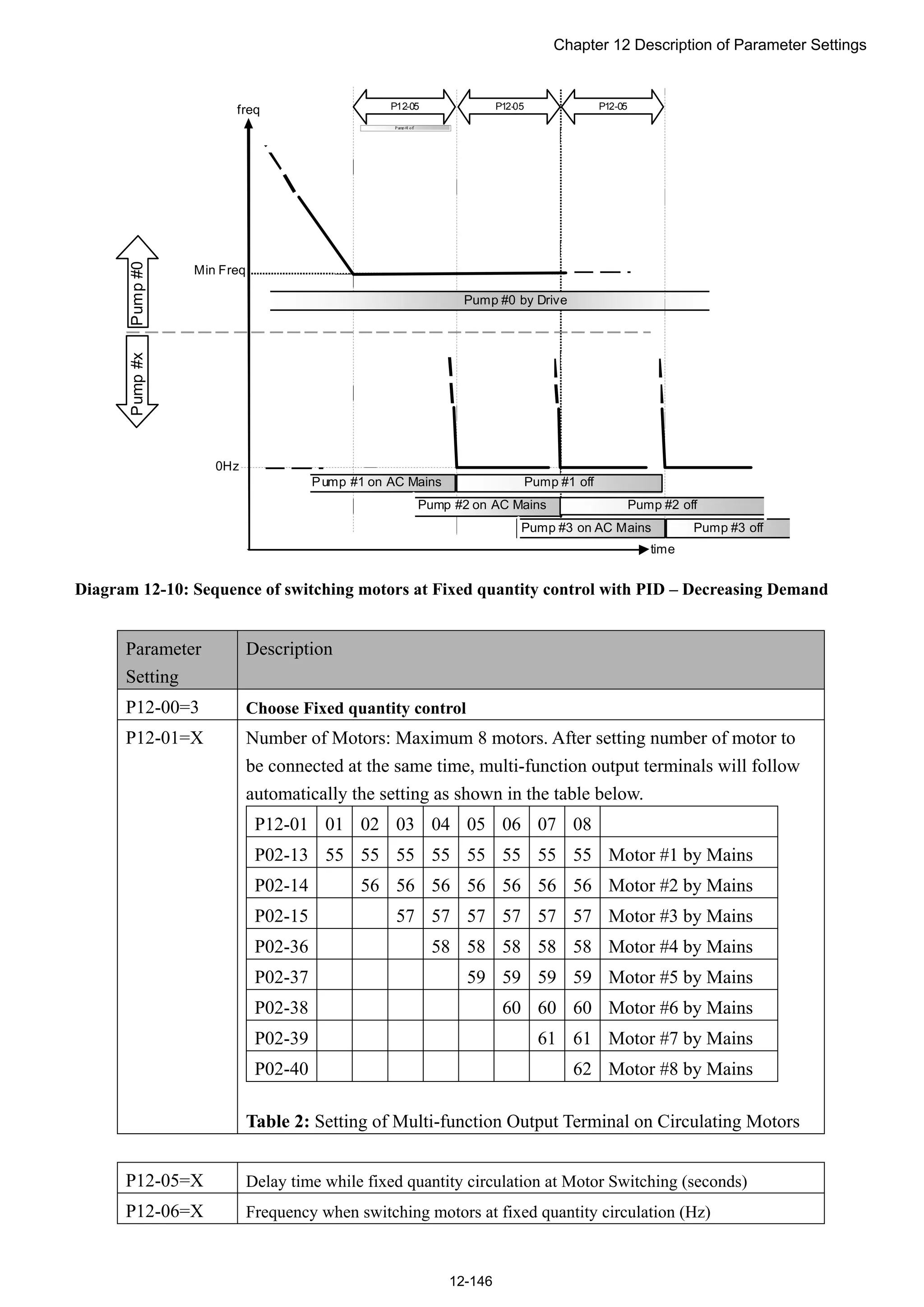
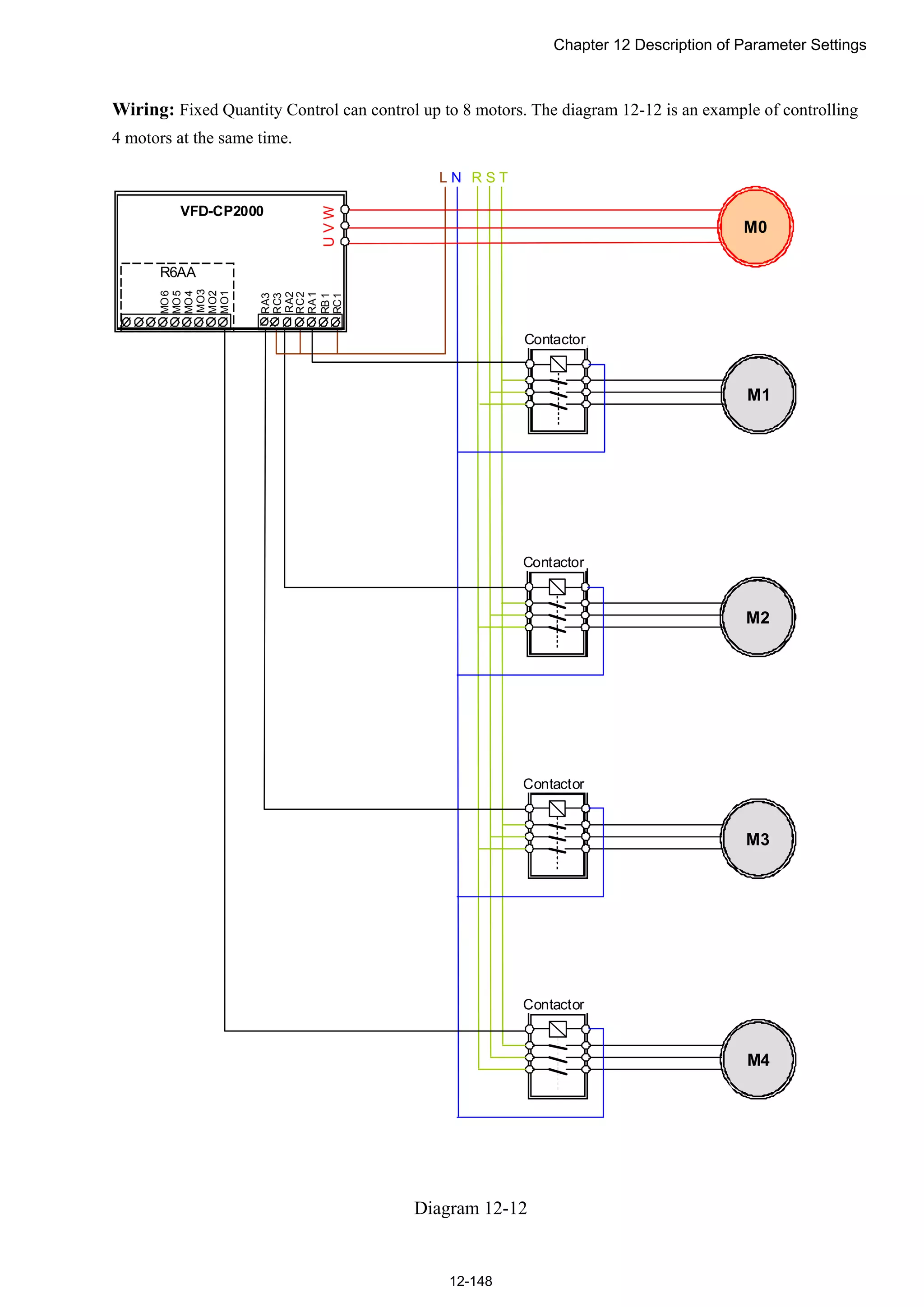
![Chapter 12 Description of Parameter Settings
12-8
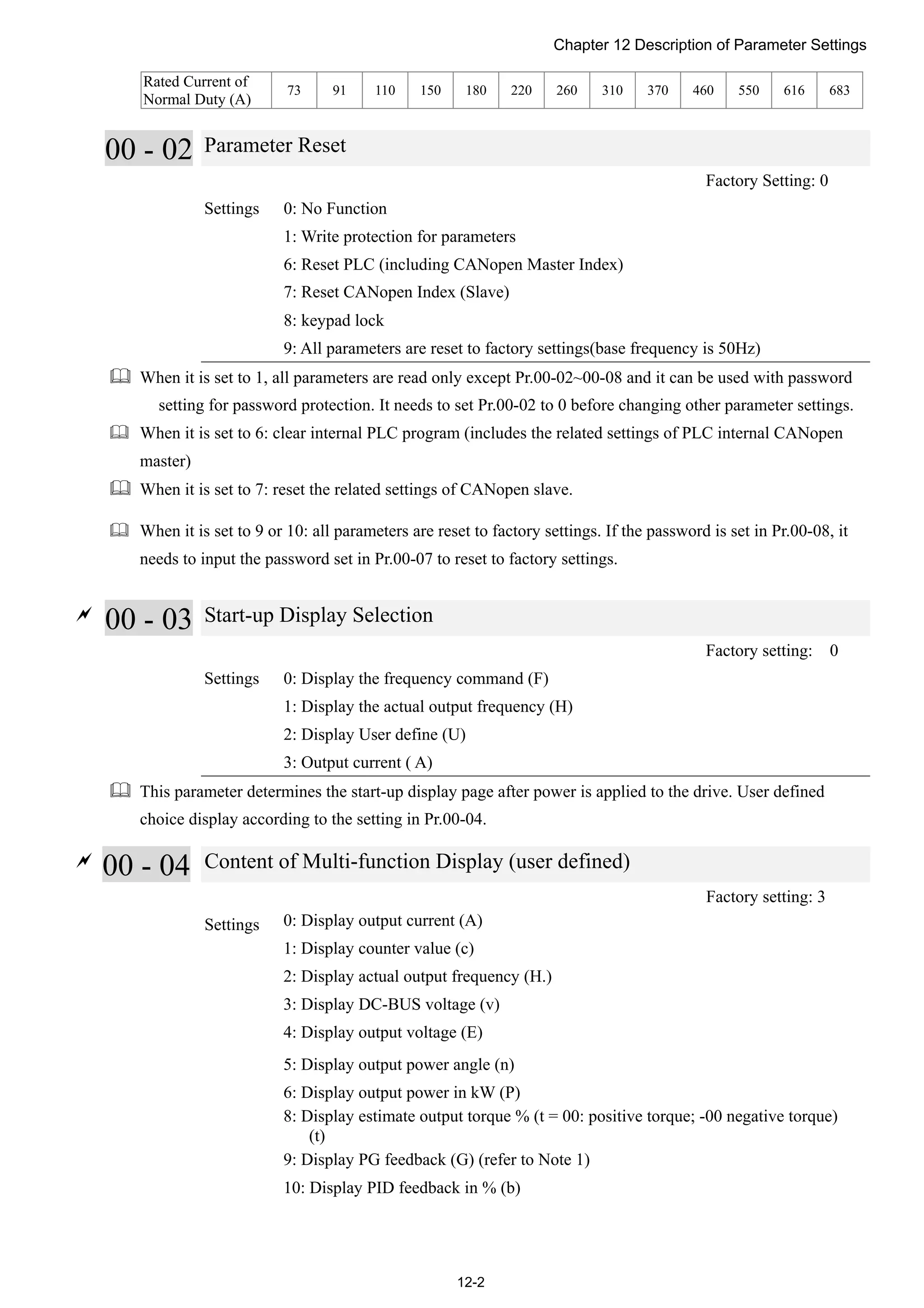
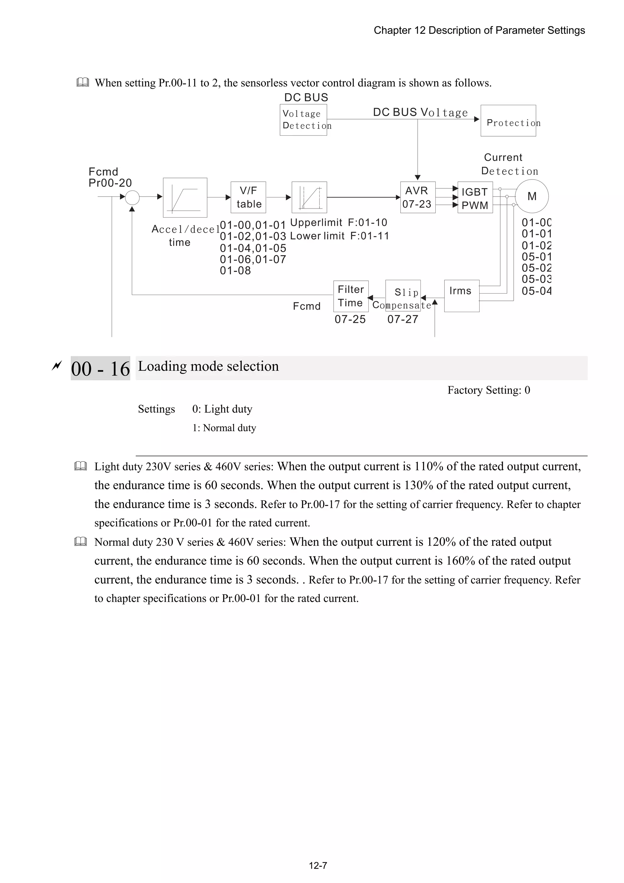
00 - 17 Carrier Frequency
Factory Setting: As shown in table below
Settings 2~15kHz
This parameter determinates the PWM carrier frequency of the AC motor drive.
230V series
Models 1-20HP [0.75-15kW] 25-60HP [18.5-45kW] 75-125HP [55-90kW]
Settings 2~15kHz 2~10kHz 2~9kHz
Light Duty Factory Setting 8kHz 6kHz 4kHz
Normal Duty Factory Setting 8 kHz 6 kHz 4 kHz
460V series
Models
1-25HP
[0.75-18.5kW]
30-100HP [22-75kW] 125-536HP [90-400kW]
Settings 2~15kHz 2~10kHz 2~9kHz
Light Duty Factory Setting 8kHz 6kHz 4kHz
Normal Duty Factory Setting 8 kHz 6 kHz 4 kHz
1kHz
8kHz
15kHz
Carrier
Frequency
Acoustic
Noise
Electromagnetic
Noise or Leakage
Current
Heat
Dissipation
Current
Wave
Significant
Minimal
Minimal Minimal
Significant Significant
由 From the table, we see that the PWM carrier frequency has a significant influence on the
electromagnetic noise, AC motor drive heat dissipation, and motor acoustic noise. Therefore, if the
surrounding noise is greater than the motor noise, lower the carrier frequency is good to reduce the
temperature rise. Although it is quiet operation in the higher carrier frequency, the entire wiring and
interference resistance should be considerate.
When the carrier frequency is higher than the factory setting, it needs to protect by decreasing the carrier
frequency. See Pr.06-55 for the related setting and details.
00 - 18 Reserved
00 - 19 PLC Command Mask
Factory Setting: Read Only
Settings Bit 0: Control command controls by PLC
Bit 1: Frequency command controls by PLC
Bit 2: Reserved
Bit 3: Reserved](https://image.slidesharecdn.com/deltacp2000men20120331-140612232906-phpapp02/75/Delta-cp2000-m_en_20120331-196-2048.jpg)
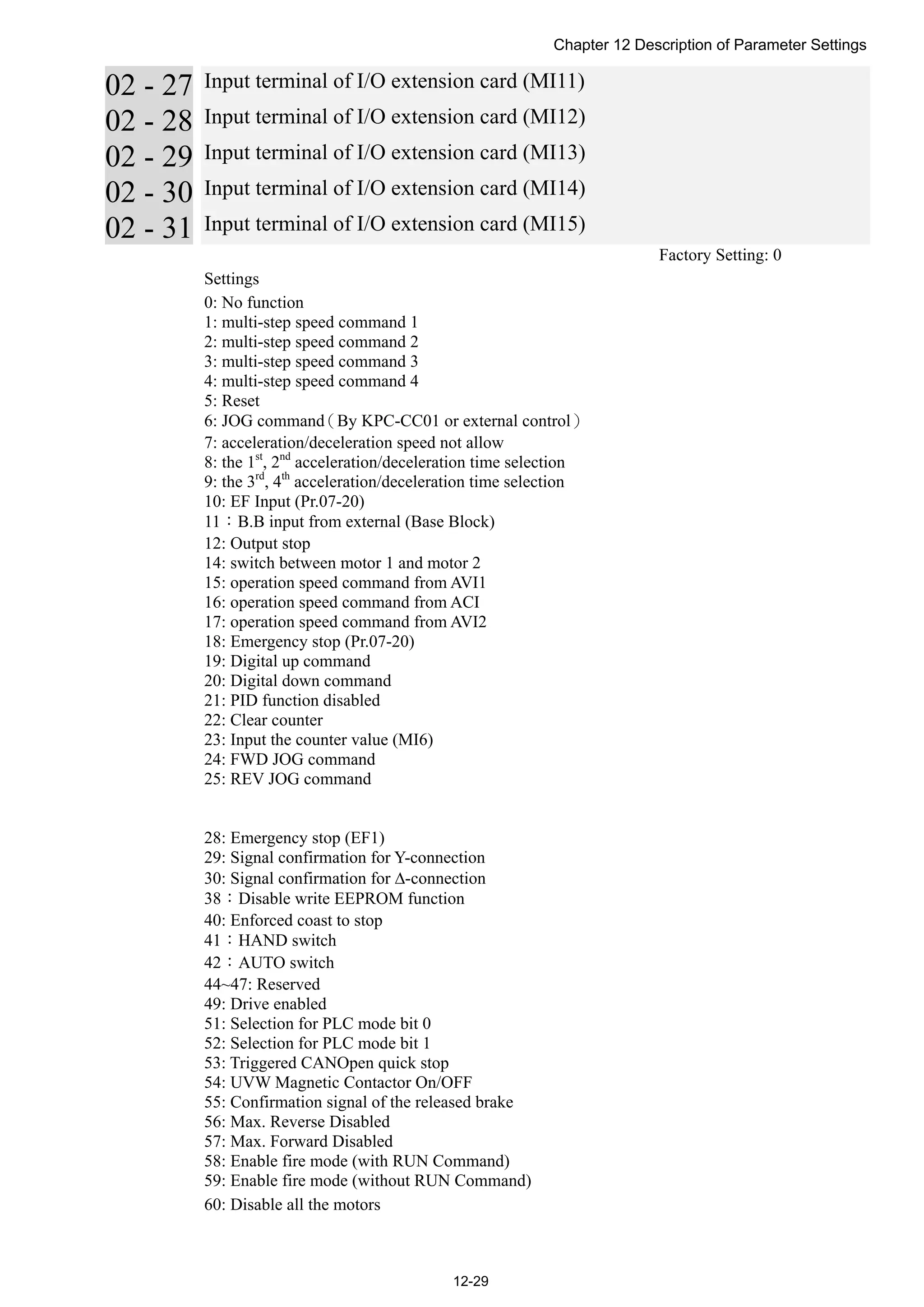
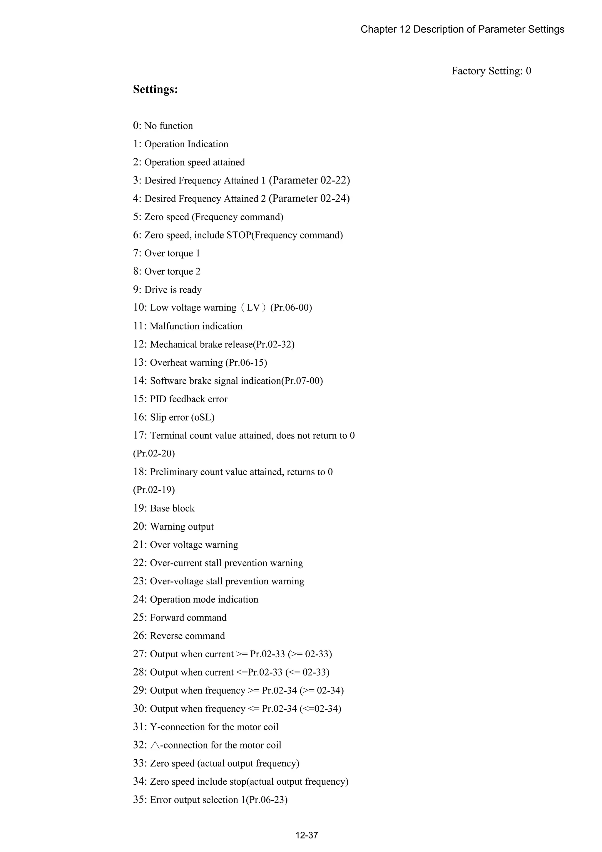
![Chapter 12 Description of Parameter Settings
12-42
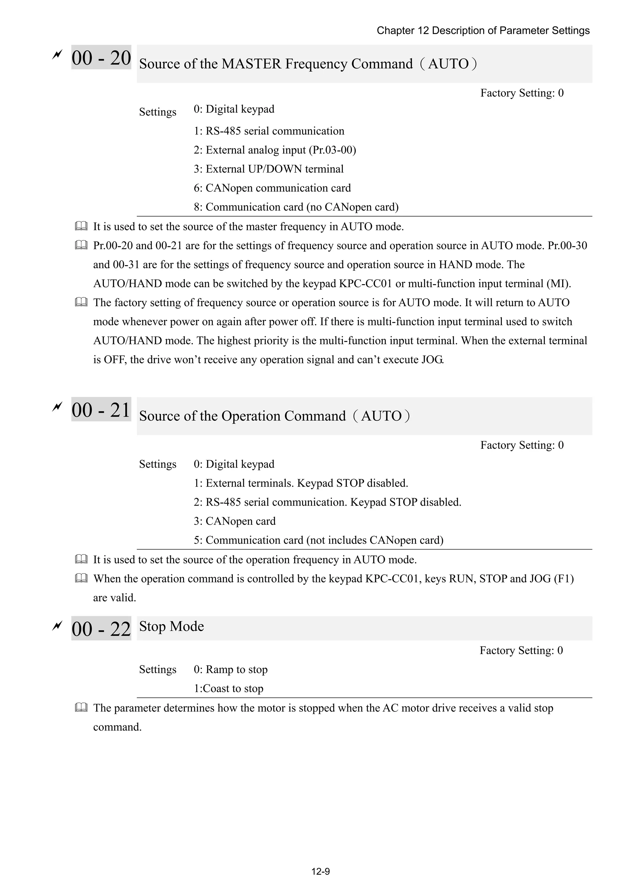
See the sequence diagram below:
1.0msec
TRG
[00-04=01]
02-14=17
02-19=5
02-20=3
[02-06=23]
Display value
Counter Trigger
(output signal)
Preliminary Counter Value
RY1 Pr.02-13=17
Terminal Counter Value
RY2 Pr.02-14=18
The width of trigger signal
02-13, 02-14, 02-36, 02-37
1.0msec
02 - 21 Digital Output Gain(DFM)
Factory Setting: 1
Settings 1~166
It is used to set the signal for the digital output terminals (DFM-DCM) and digital frequency output (pulse
X work period=50%). Output pulse per second = output frequency X Pr.02-21.
02 - 22 Desired Frequency Attained 1
Factory Setting: 60.00/50.00
Settings 0.00~600.00Hz
02 - 24 Desired Frequency Attained 2
Factory Setting: 60.00/50.00
Settings 0.00~600.00Hz
02 - 23 The Width of the Desired Frequency Attained 1
Factory Setting: 2.00
Settings 0.00~600.00Hz
02 - 25 The Width of the Desired Frequency Attained 2
Factory Setting: 2.00
Settings 0.00~600.00Hz
Once output frequency reaches desired frequency and the corresponding multi-function output terminal is
set to 3 or 4 (Pr.02-13, 02-14, 02-36, and 02-37), this multi-function output terminal will be ON.](https://image.slidesharecdn.com/deltacp2000men20120331-140612232906-phpapp02/75/Delta-cp2000-m_en_20120331-230-2048.jpg)

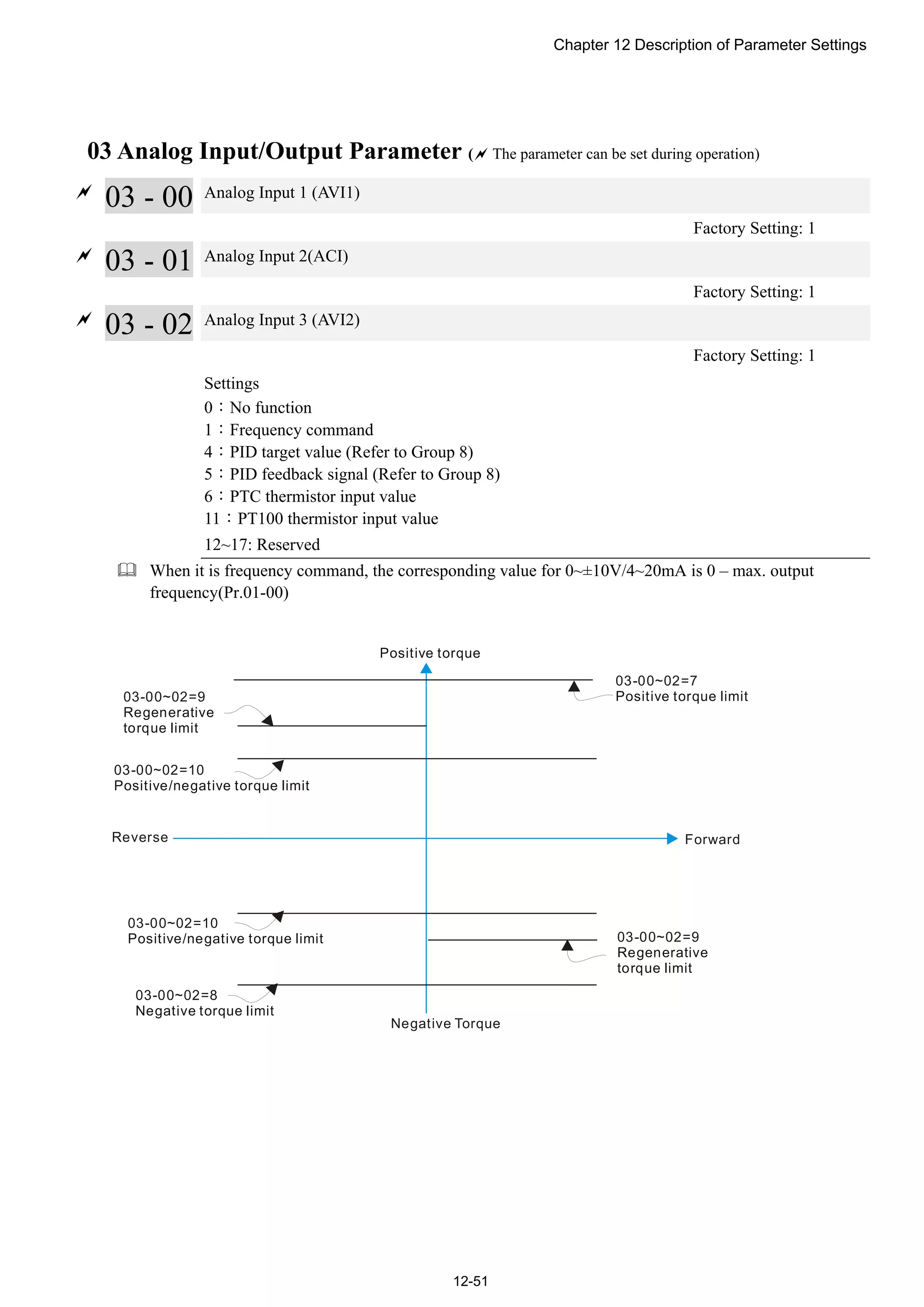
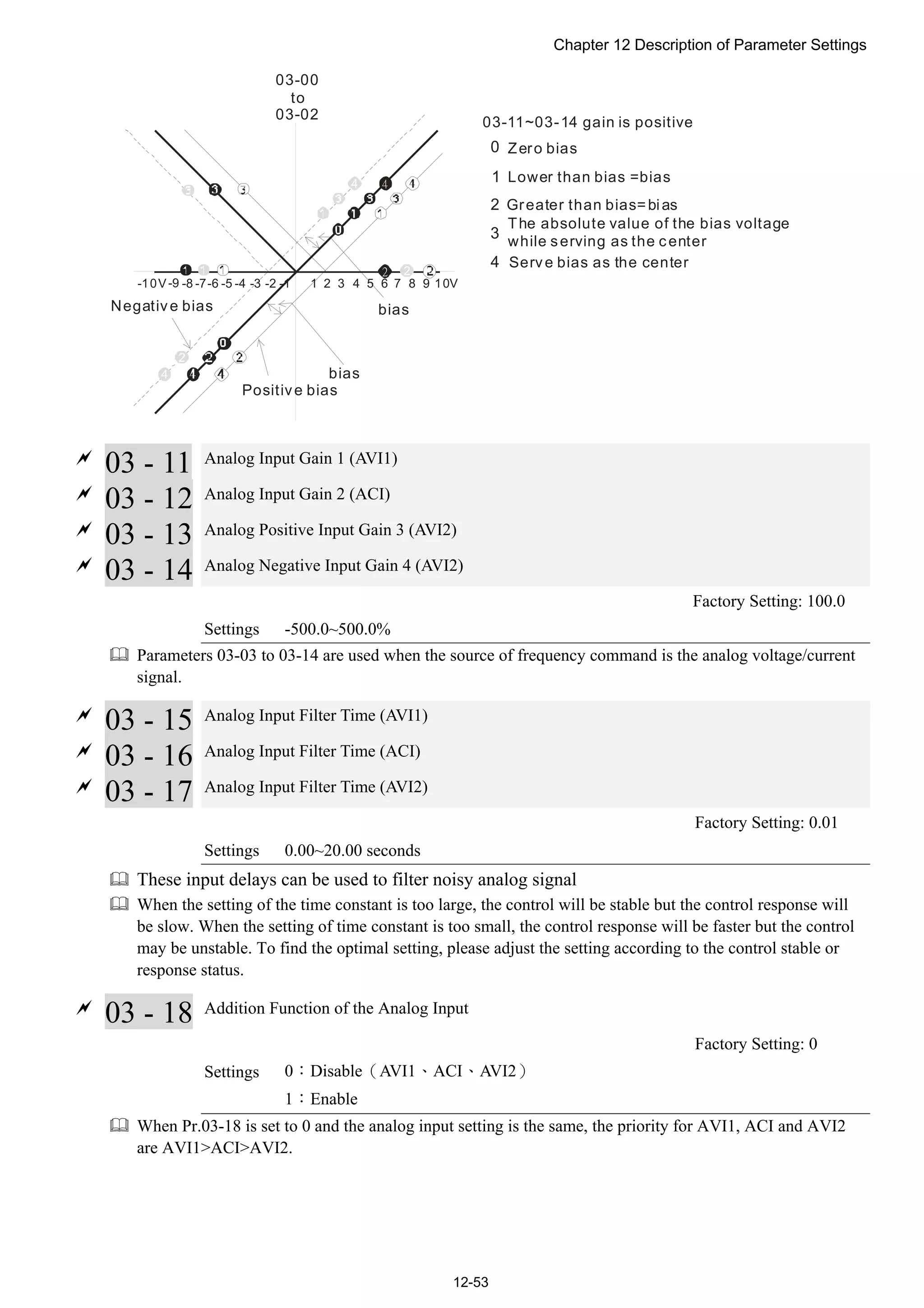
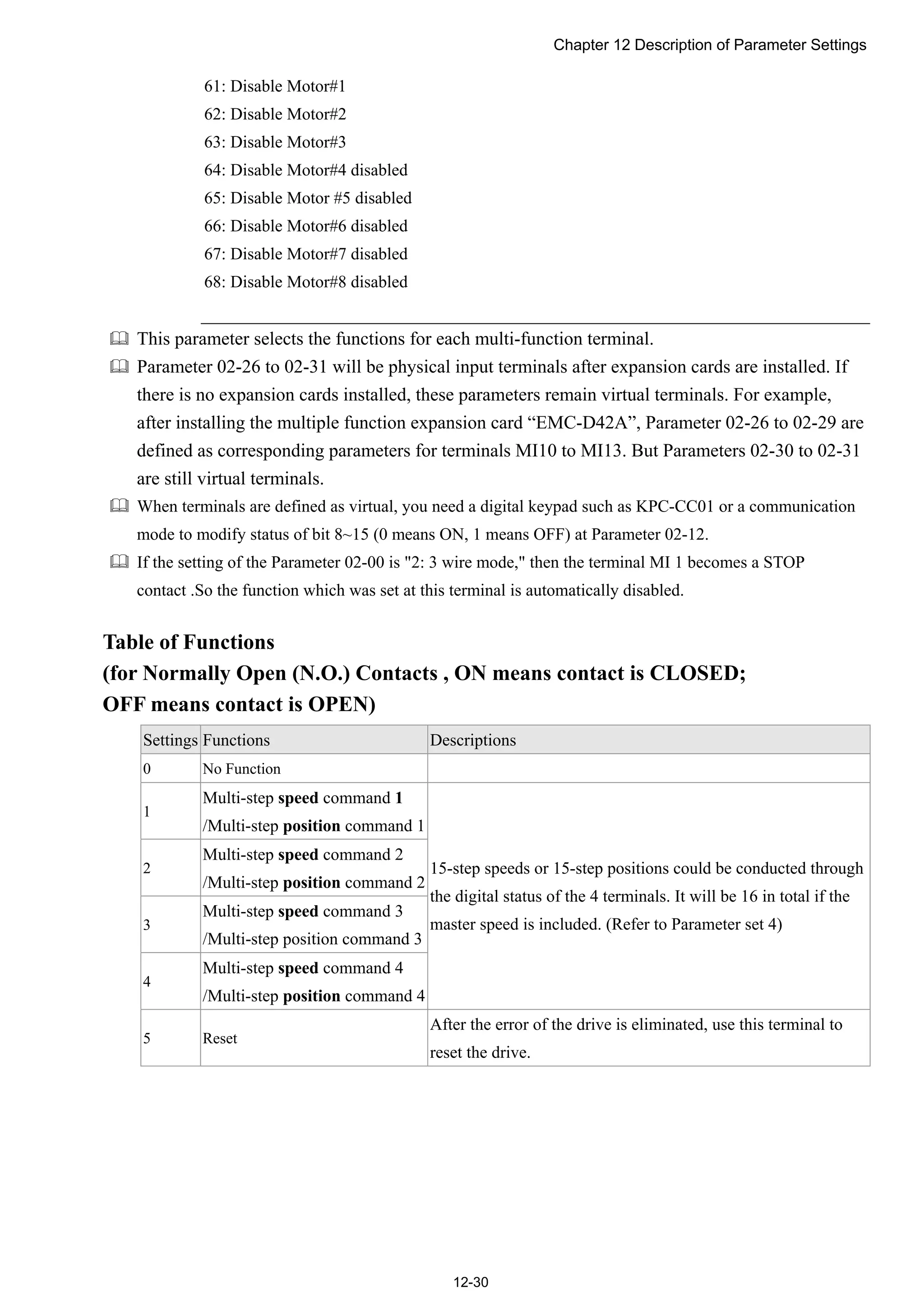
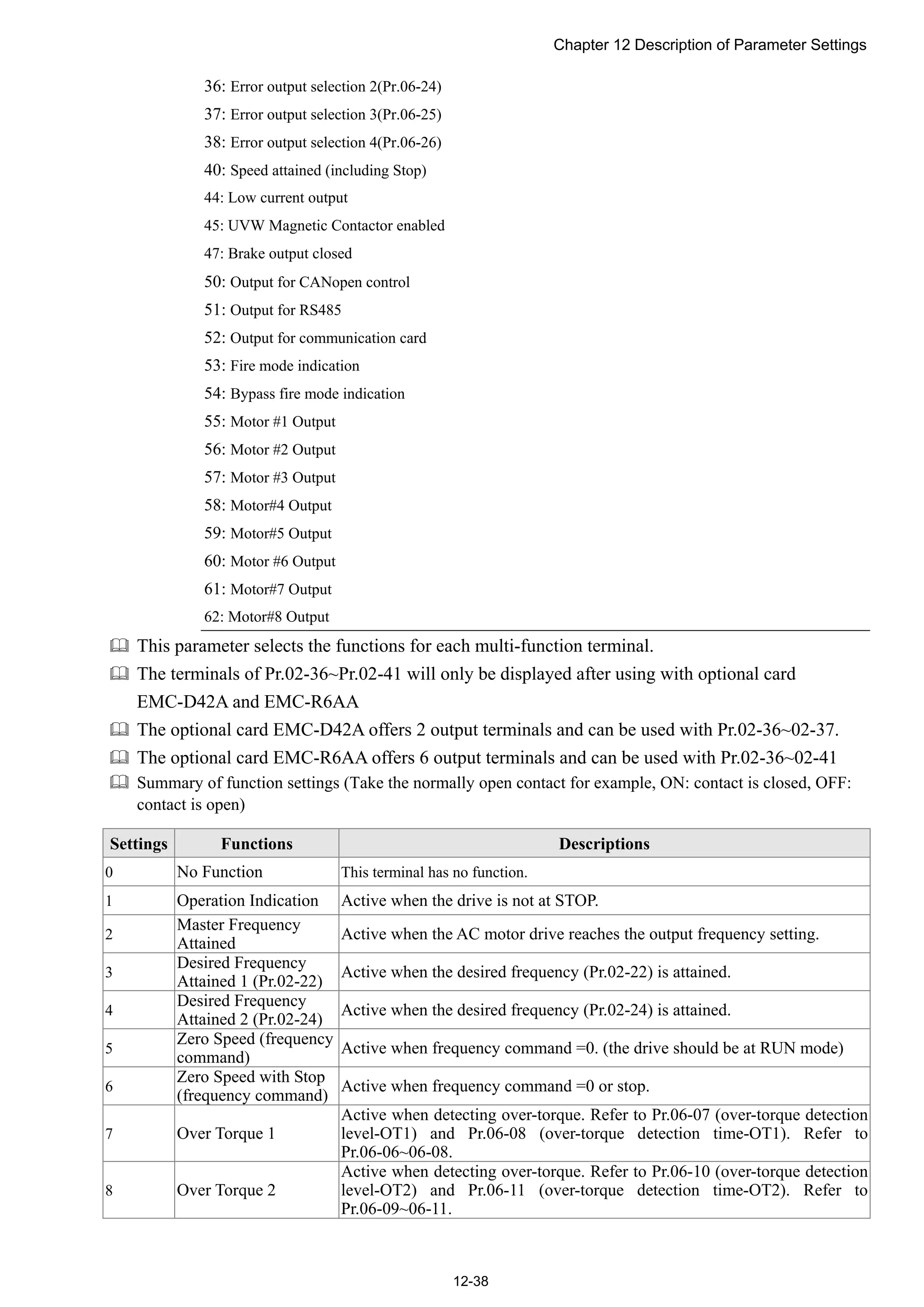
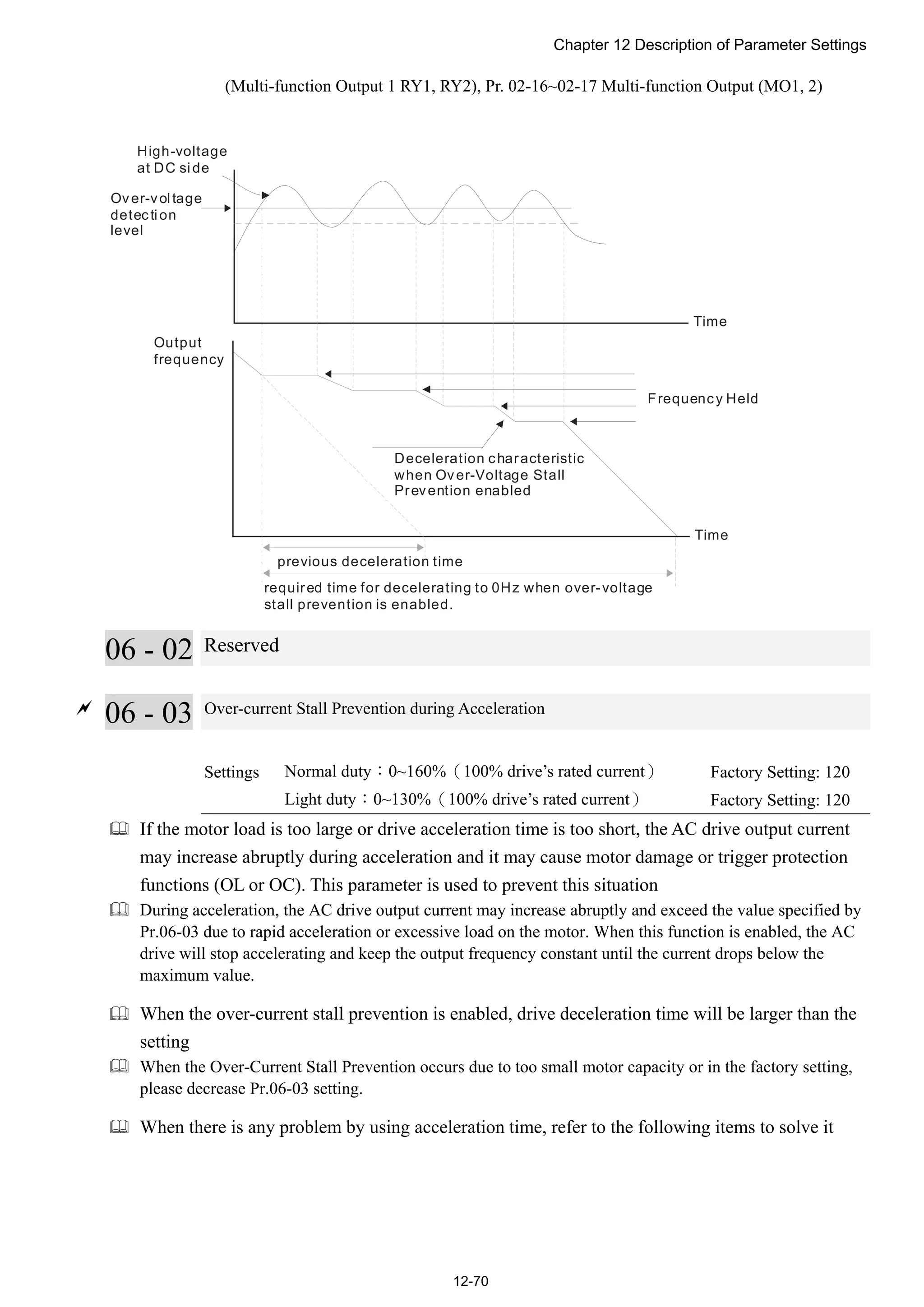
![Chapter 12 Description of Parameter Settings
12-54
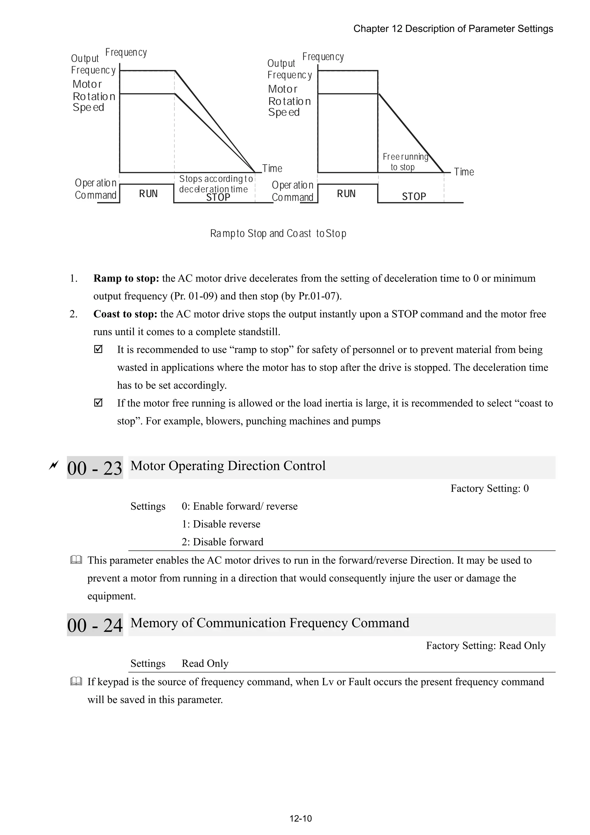
Fco mmand=[(ay bias)*gain]* Fma x(01-00)
10V or 16mA
ay : 10 or 16mA
bias : Pr.03-03,Pr. 0 3-04 , Pr.03-05
gain : Pr.03-11, Pr.03-12, Pr.0 3-13 , Pr.03-14
Freque ncy
Voltage
Fcomman d: t he corresp onding
frequen cy for 10V or 20mA
03 - 19 Loss of the ACI Signal
Factory Setting: 0
Settings 0: Disable
1: Continue operation at the last frequency
2: Decelerate to stop
3: top immediately and display ACE
This parameter determines the behAVI1or when ACI is lost.
When Pr.03-29 is set to 1, it means ACI terminal is for 0-10V voltage input. At this moment, Pr.03-19 will
be invalid.
When setting is 1 or 2, it will display warning code “AnL” on the keypad. It will be blinking until
the loss of the ACI signal is recovered or drive is stop
03 - 20 Multi-function Output 1 (AFM1)
Factory Setting: 0
03 - 23 Multi-function Output 2 (AFM2)
Factory Setting: 0
Settings 0~23
Function Chart
Settings Functions Descriptions
0 Output frequency (Hz) Max. frequency Pr.01-00 is regarded as 100%.
1 Frequency command (Hz) Max. frequency Pr.01-00 is regarded as 100%.
2 Motor speed (Hz) 600Hz is regarded as 100%
3 Output current (rms) (2.5 X rated current) is regarded as 100%
4 Output voltage (2 X rated voltage) is regarded as 100%
5 DC Bus Voltage 450V (900V)=100%
6 Power factor -1.000~1.000=100%
7 Power Rated power is regarded as 100%
8 Output torque Full-load torque is regarded as 100%](https://image.slidesharecdn.com/deltacp2000men20120331-140612232906-phpapp02/75/Delta-cp2000-m_en_20120331-242-2048.jpg)


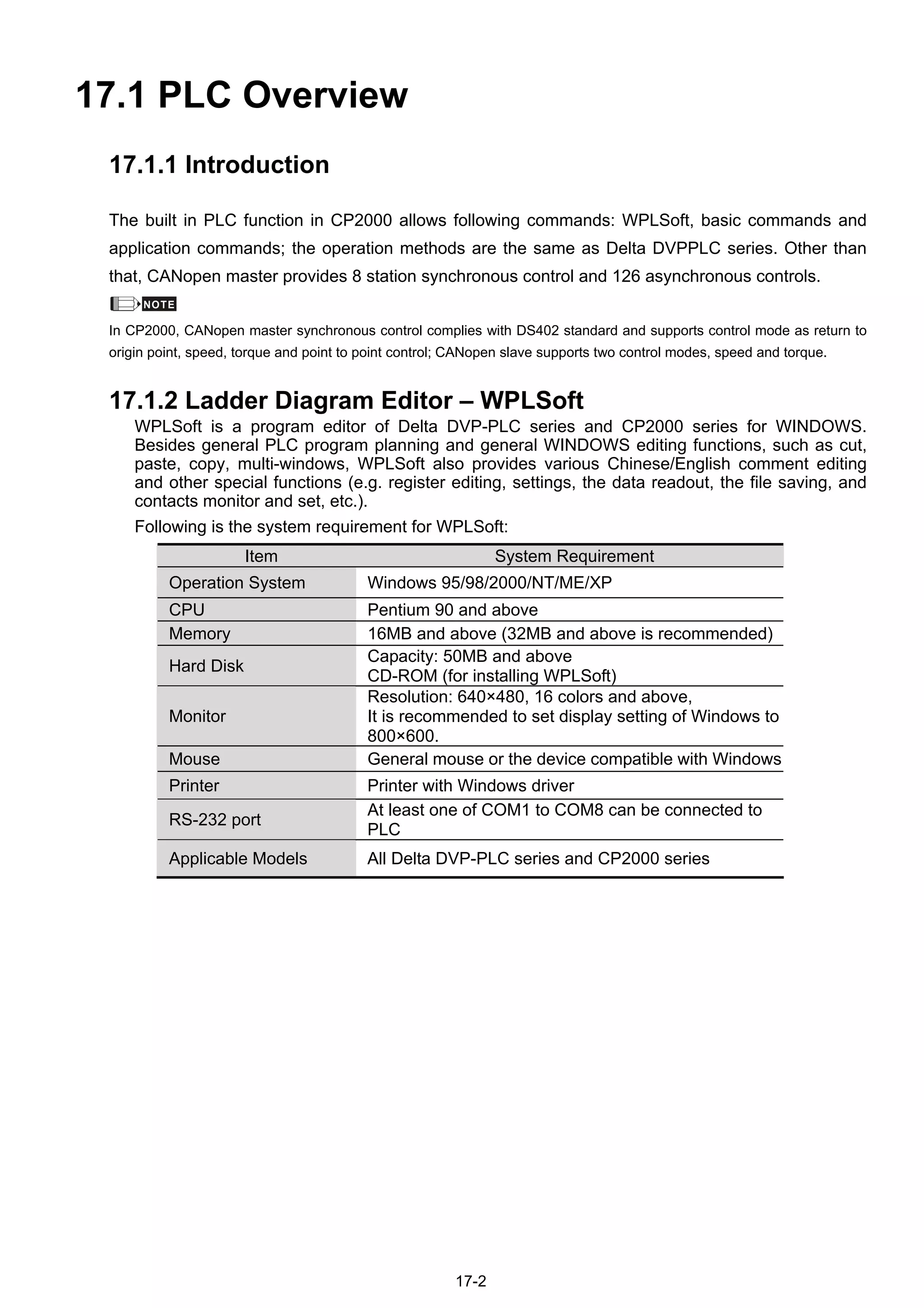

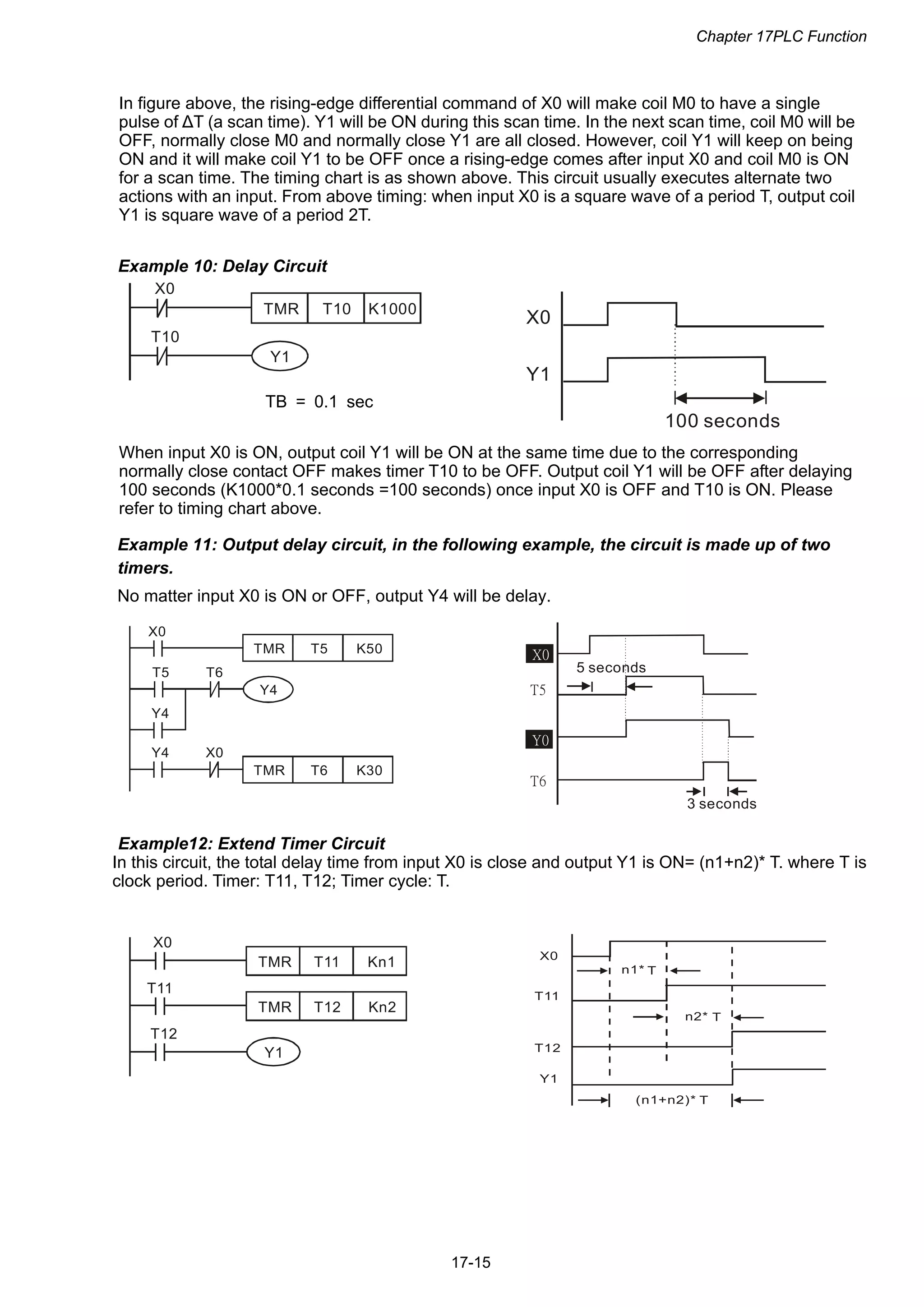
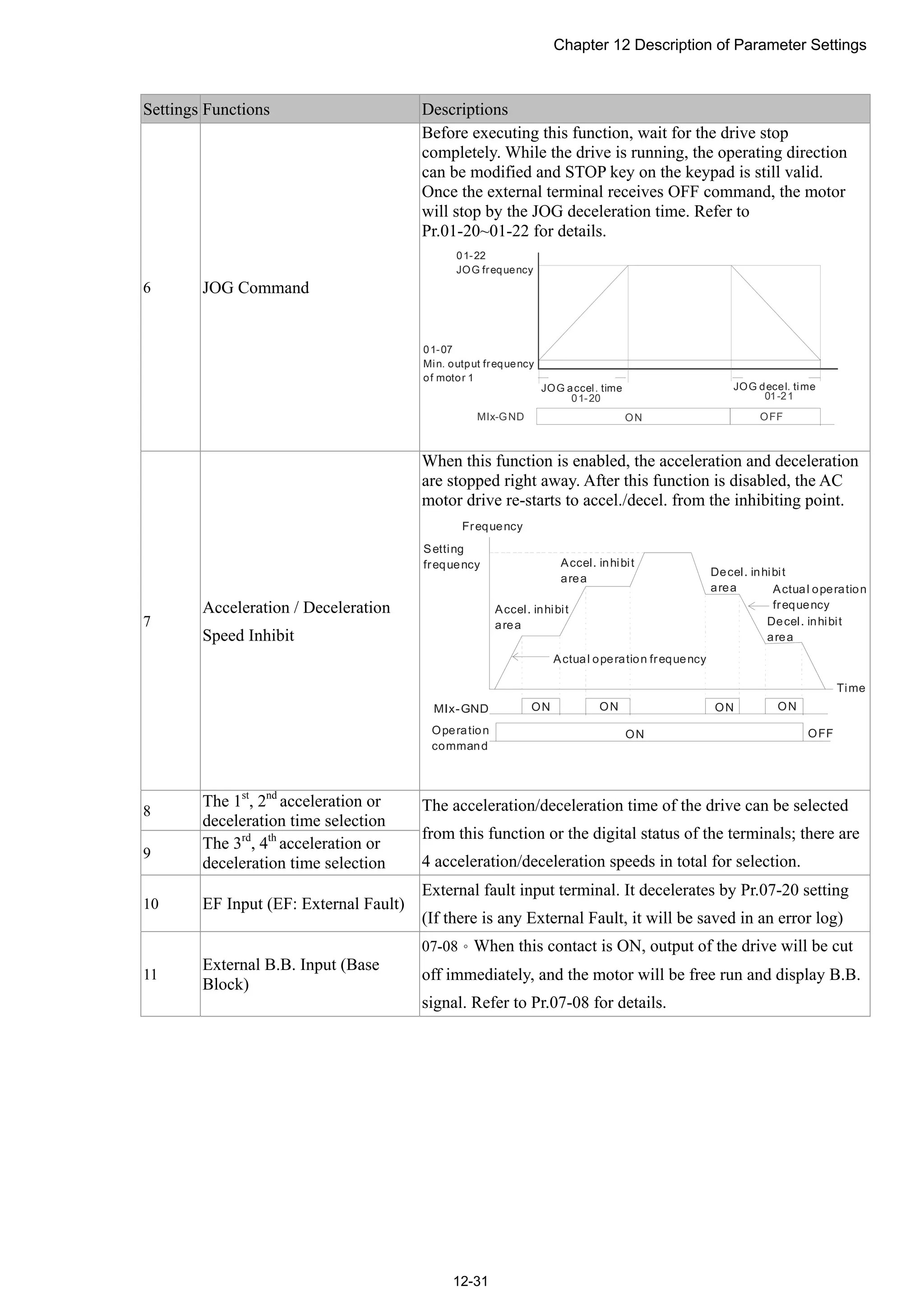
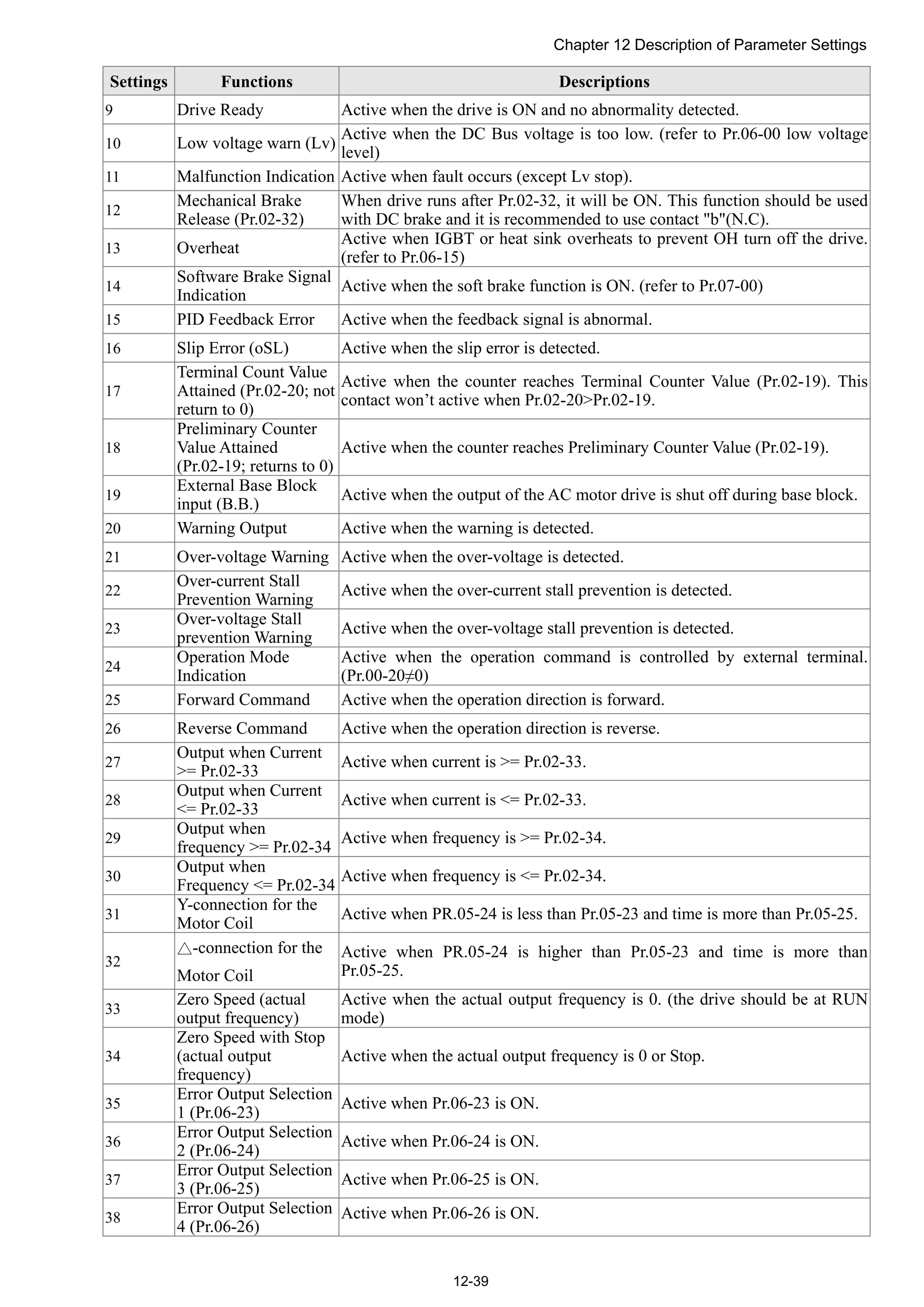
![Chapter 17PLC Function
17-17
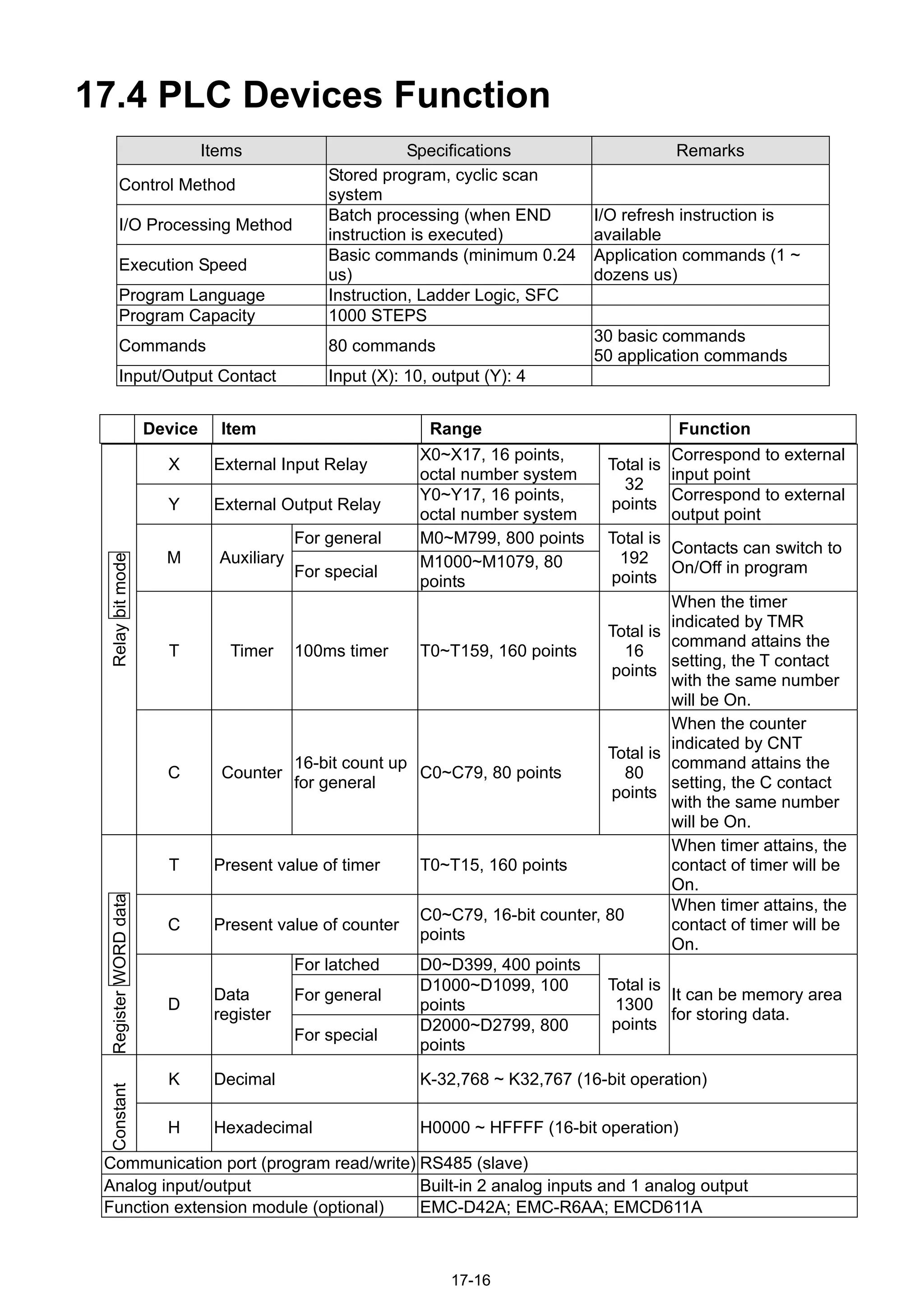
17.4.1 Devices Functions
The Function of Input/output Contacts
The function of input contact X: input contact X reads input signal and enter PLC by connecting with
input equipment. It is unlimited usage times for contact A or contact B of each input contact X in
program. The On/Off of input contact X can be changed with the On/Off of input equipment but can’t
be changed by using peripheral equipment (WPLSoft).
The Function of Output Contact Y
The mission of output contact Y is to drive the load that connects to output contact Y by sending
On/Off signal. There are two kinds of output contact: one is relay and the other is transistor. It is
unlimited usage times for A or B contact of each output contact Y in program. But there is number for
output coil Y and it is recommended to use one time in program. Otherwise, the output result will be
decided by the circuit of last output Y with PLC program scan method.
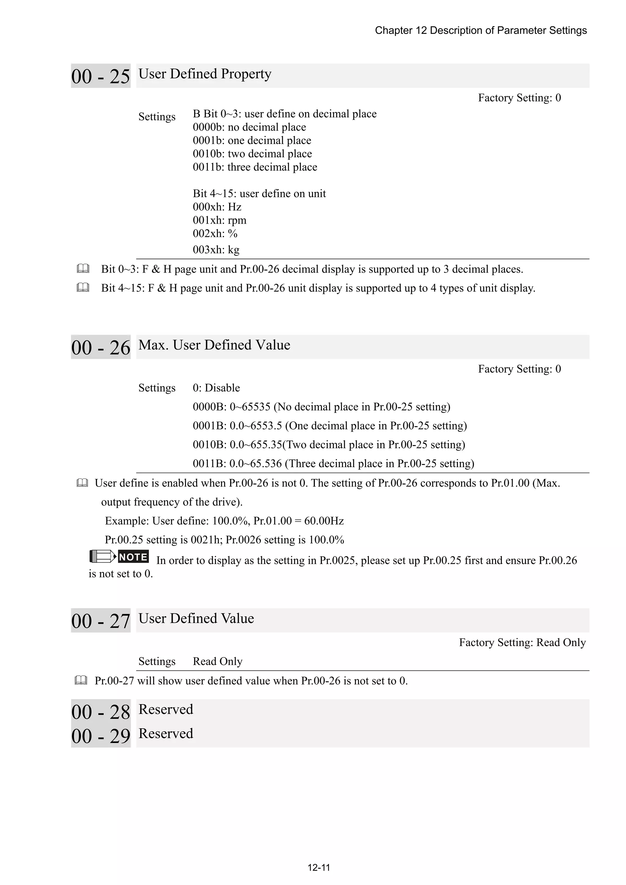
X0
X10
Y0
Y0
1
2
Y0 is repeated
The output of Y0 will be decided by
circuit ○2, i.e. decided by On/Off of
X10.
Value, Constant [K] / [H]
K Decimal K-32,768 ~ K32,767 (16-bit operation)
Constant
H Hexadecimal H0000 ~ HFFFF (16-bit operation)
There are five value types for DVP-PLC to use by the different control destination. The following is
the explanation of value types.
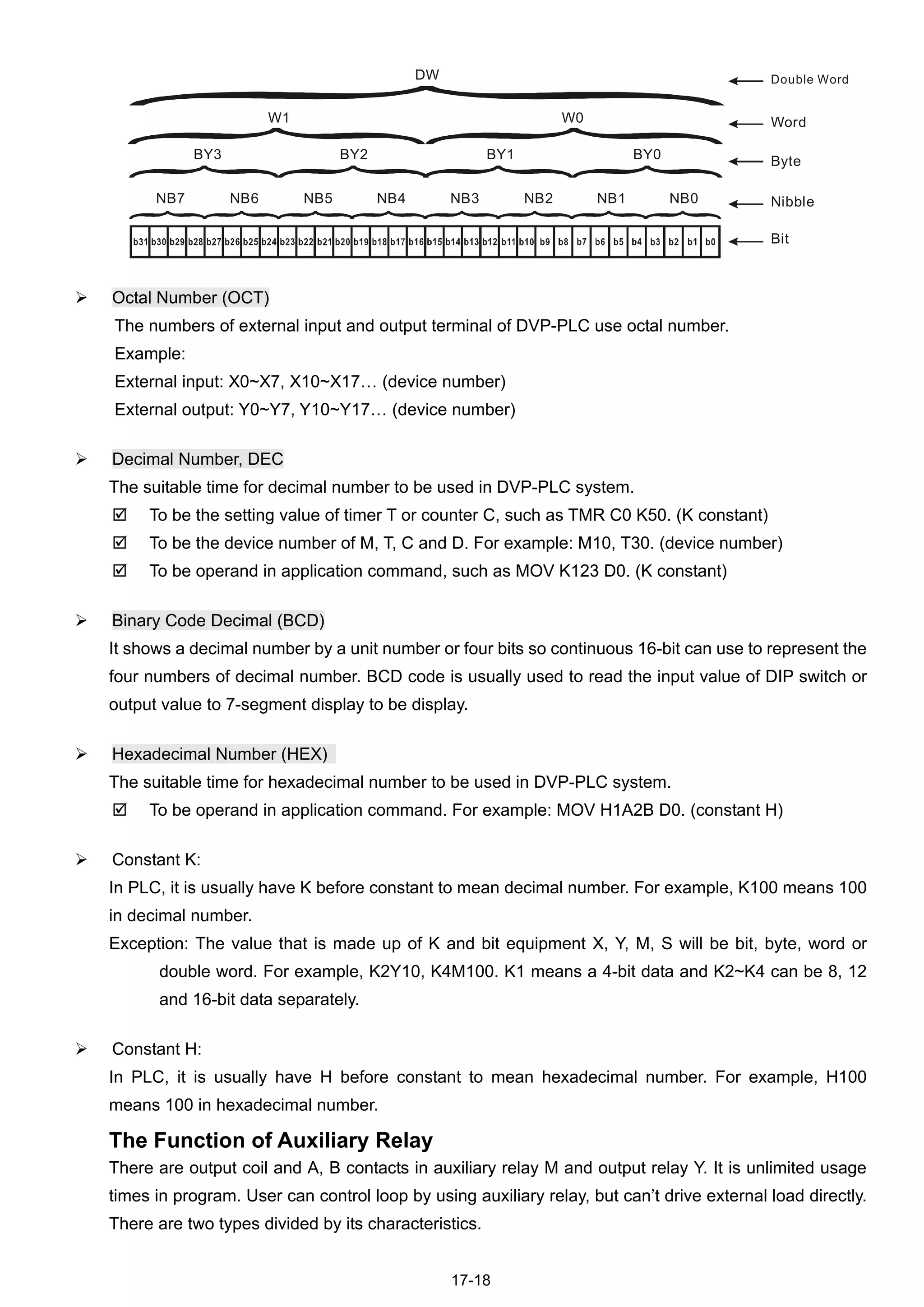
Binary Number (BIN)
It uses binary system for the PLC internal operation or storage. The relative information of binary
system is in the following.
Bit Bit is the basic unit of binary system, the status are 1 or 0.
Nibble It is made up of continuous 4 bits, such as b3~b0. It can be used to
represent number 0~9 of decimal or 0~F of hexadecimal.
Byte It is made up of continuous 2 nibbles, i.e. 8 bits, b7~b0. It can used to
represent 00~FF of hexadecimal system.
Word It is made up of continuous 2 bytes, i.e. 16-bit, b15~b0. It can used to
represent 0000~FFFF of hexadecimal system.
Double Word It is made up of continuous 2 words, i.e. 32-bit, b31~b0. It can used to
represent 00000000~FFFFFFFF of hexadecimal system.
The relations among bit, nibble, byte, word, and double word of binary number are shown as follows.](https://image.slidesharecdn.com/deltacp2000men20120331-140612232906-phpapp02/75/Delta-cp2000-m_en_20120331-404-2048.jpg)
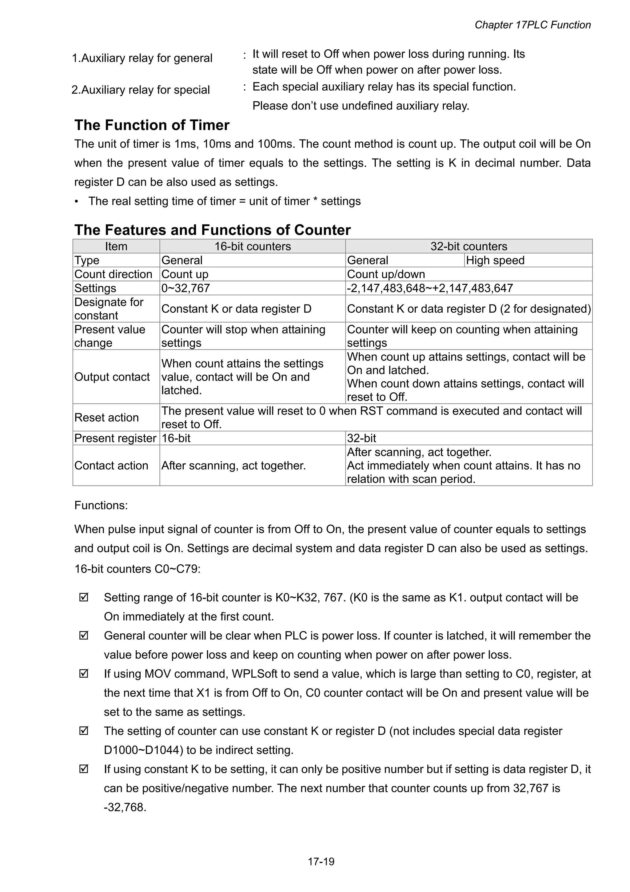


This document provides instructions and safety information for installing and inspecting a CP2000 series AC motor drive. It describes what to check when receiving the drive, including verifying model name and voltage rating. Wiring instructions and terminal information are also included. The document discusses the optional RFI jumper, which can be removed to isolate the main power from earth for certain applications. Cutting the jumper may reduce EMC performance and increase leakage currents, so instructions are provided on when it is appropriate to cut the jumper.


![Ct2000 pro plus_manual_english[1]](https://cdn.slidesharecdn.com/ss_thumbnails/ct2000proplusmanualenglish1-140613213527-phpapp02-thumbnail.jpg?width=640&height=640&fit=bounds)

![Ct2000 es manual_english_version_1[1].0](https://cdn.slidesharecdn.com/ss_thumbnails/ct2000esmanualenglishversion11-140613213448-phpapp01-thumbnail.jpg?width=640&height=640&fit=bounds)


![Coded Agents – with UiPath SDK + LangGraph [Virtual Hands-on Workshop]](https://cdn.slidesharecdn.com/ss_thumbnails/codedagentsdeck-251215155422-5497c599-thumbnail.jpg?width=640&height=640&fit=bounds)


