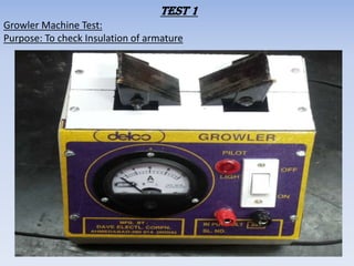
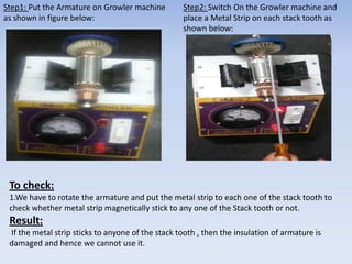
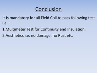
Procedure For Armature & Field 
Coil Inspection 
Prepared By: 
Abhishek Kr. Gautam 
Executive-QA-Power Tools
Armature Testing
Test 1 
Growler Machine Test: 
Purpose: To check Insulation of armature
Step1: Put the Armature on Growler machine 
as shown in figure below: 
Step2: Switch On the Growler machine and 
place a Metal Strip on each stack tooth as 
shown below: 
To check: 
1.We have to rotate the armature and put the metal strip to each one of the stack tooth to 
check whether metal strip magnetically stick to any one of the Stack tooth or not. 
Result: 
If the metal strip sticks to anyone of the stack tooth , then the insulation of armature is 
damaged and hence we cannot use it.
Test 2 
Multimeter Test: 
Purpose: To check Continuity and Balancing of Armature
Step1: Switch On the multimeter and put 2 
Multimeter Pins at Commutator bars which 
are at 180º opposite to each other. 
Step2: Repeat step 1 for each equally 
opposite pairs of Commutator bars. 
To check: 
The readings for all Commutator bar Pairs should be exactly same. Example 2.2 mA for all 
pairs. 
Result: 
If the reading for all Commutator bar pair is same then Armature is Ok in terms of 
Continuity and Balancing.
Step3: Switch On the multimeter and put one Multimeter Pin on Commutator bar and another 
one on stack tooth as shown below. 
To check: 
Response of Multimeter to detect any Insulation Damage. 
Result: 
If during this test there is no response from multimeter then we can conclude that 
Insulation of armature is Ok. Hence we can use the armature.
Conclusion 
It Is mandatory for all armatures to pass following 
test i.e. 
1.Growler Machine Test. 
2.Multimeter Test . 
3.Aesthetics i.e. no damage, no Rust etc.
Field Coil Testing
Test 1 
Multimeter Test: 
Purpose: To check Continuity and Insulation
Step1: Switch On the multimeter and put 1 
Multimeter Pins at INLET wire and Other one 
at OUTLET wire of same side as shown below. 
Step2: Repeat step 1 for other set of INLET & 
OUTLET wire. 
Same Side Inlet and 
Outlet Connection 
Other set of Inlet and 
Outlet Connection 
To check: 
Reading on Multimeter should be same for Both set of INLET & OUTLET Connection. 
Result: 
If the reading On multimeter for both set of INLET & OUTLET connection is same then 
Field Coil is Ok in terms of Continuity and Balancing. Hence we can use the Field Coil. 
For Example: In the above image there is difference in reading for both set of INLET & 
OUTLET connection so the Field coil is Not Ok.
Step3: Switch On the multimeter and put one Multimeter Pin on Field Coil stack and another 
one on Outlet/Inlet wire as shown below. 
To check: 
Response of Multimeter to detect any Insulation Damage. 
Result: 
If during this test there is no response from multimeter then we can conclude that 
Insulation of Field Coil is Ok. Hence we can use the armature.
Conclusion 
It Is mandatory for all Field Coil to pass following test 
i.e. 
1.Multimeter Test for Continuity and Insulation. 
2.Aesthetics i.e. no damage, no Rust etc.
ThankYou

Armature & field coil inspection

  • 1.
    Procedure For Armature& Field Coil Inspection Prepared By: Abhishek Kr. Gautam Executive-QA-Power Tools
  • 2.
  • 3.
    Test 1 GrowlerMachine Test: Purpose: To check Insulation of armature
  • 4.
    Step1: Put theArmature on Growler machine as shown in figure below: Step2: Switch On the Growler machine and place a Metal Strip on each stack tooth as shown below: To check: 1.We have to rotate the armature and put the metal strip to each one of the stack tooth to check whether metal strip magnetically stick to any one of the Stack tooth or not. Result: If the metal strip sticks to anyone of the stack tooth , then the insulation of armature is damaged and hence we cannot use it.
  • 5.
    Test 2 MultimeterTest: Purpose: To check Continuity and Balancing of Armature
  • 6.
    Step1: Switch Onthe multimeter and put 2 Multimeter Pins at Commutator bars which are at 180º opposite to each other. Step2: Repeat step 1 for each equally opposite pairs of Commutator bars. To check: The readings for all Commutator bar Pairs should be exactly same. Example 2.2 mA for all pairs. Result: If the reading for all Commutator bar pair is same then Armature is Ok in terms of Continuity and Balancing.
  • 7.
    Step3: Switch Onthe multimeter and put one Multimeter Pin on Commutator bar and another one on stack tooth as shown below. To check: Response of Multimeter to detect any Insulation Damage. Result: If during this test there is no response from multimeter then we can conclude that Insulation of armature is Ok. Hence we can use the armature.
  • 8.
    Conclusion It Ismandatory for all armatures to pass following test i.e. 1.Growler Machine Test. 2.Multimeter Test . 3.Aesthetics i.e. no damage, no Rust etc.
  • 9.
  • 10.
    Test 1 MultimeterTest: Purpose: To check Continuity and Insulation
  • 11.
    Step1: Switch Onthe multimeter and put 1 Multimeter Pins at INLET wire and Other one at OUTLET wire of same side as shown below. Step2: Repeat step 1 for other set of INLET & OUTLET wire. Same Side Inlet and Outlet Connection Other set of Inlet and Outlet Connection To check: Reading on Multimeter should be same for Both set of INLET & OUTLET Connection. Result: If the reading On multimeter for both set of INLET & OUTLET connection is same then Field Coil is Ok in terms of Continuity and Balancing. Hence we can use the Field Coil. For Example: In the above image there is difference in reading for both set of INLET & OUTLET connection so the Field coil is Not Ok.
  • 12.
    Step3: Switch Onthe multimeter and put one Multimeter Pin on Field Coil stack and another one on Outlet/Inlet wire as shown below. To check: Response of Multimeter to detect any Insulation Damage. Result: If during this test there is no response from multimeter then we can conclude that Insulation of Field Coil is Ok. Hence we can use the armature.
  • 13.
    Conclusion It Ismandatory for all Field Coil to pass following test i.e. 1.Multimeter Test for Continuity and Insulation. 2.Aesthetics i.e. no damage, no Rust etc.
  • 14.