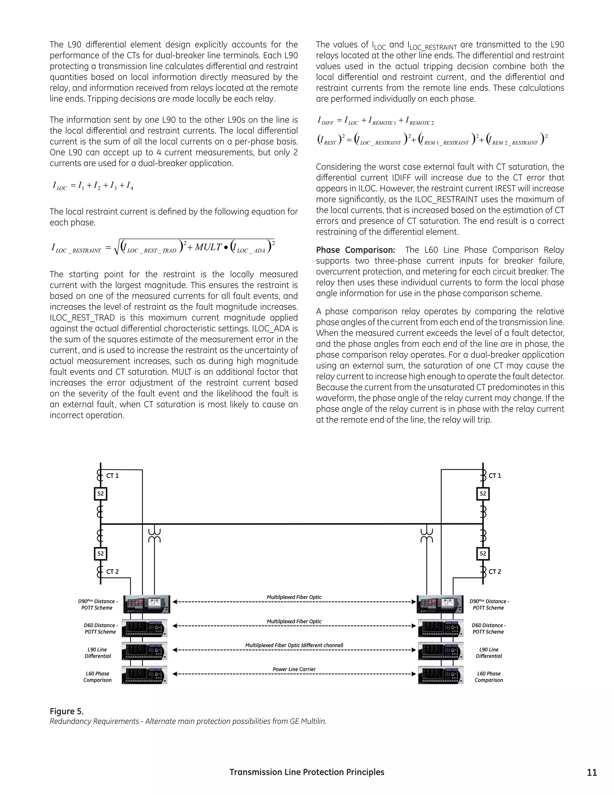
This document discusses transmission line protection principles. It begins by introducing transmission lines and the importance of quickly detecting and isolating faults on lines. It then discusses factors that influence line protection design like line criticality, fault clearing times, line configuration, and loading. The document focuses on advantages of GE Multilin relays for transmission line protection, including their ability to handle single pole tripping, communicate between line terminals reliably, and operate securely at dual breaker terminals by directly measuring individual breaker currents.
This document discusses relays, including their basic components, design, operation, applications, advantages, and disadvantages. Relays are electrical devices that use electromagnets to open or close circuits. They have a coil, armature, contacts, and frame. When voltage is applied to the coil, it creates a magnetic field that moves the armature to open or close the contacts. Relays allow low power circuits to control high power circuits and are used for protection, regulation, and auxiliary functions in power systems.
This document discusses pilot protection schemes for transmission lines. Pilot schemes use communication channels between line terminals to provide instantaneous clearing of faults over the entire line length. Common pilot schemes described include permissive overreaching transfer trip (POTT), directional comparison blocking (DCB), and directional comparison unblocking (DCUB). Redundant pilot channels and protection principles are recommended to improve the reliability and security of pilot schemes. Desirable relay features include integrated functions for weak infeed conditions as well as sensitive directional overcurrent elements to key the pilot communications.
Protection of transmission lines (distance)Rohini Haridas
This gives idea about necessity of protection of transmission line and protection based on time grading as well as on current grading. Also includes three step distance protection of transmission line
It’s a power electronics project. It is able to give output voltage(DC) more and less than input voltage as per requirement.
We can generate variable DC voltage which is less than input, but, the special things about this converter is, it has capability to produce variable DC voltage as high as twice the input voltage.
We have specially designed and manufactured inductor for this project.
Unit I: Introduction to Protection System:
Introduction to protection system and its elements, functions of protective relaying, protective zones, primary and backup protection, desirable qualities of protective relaying, basic terminology.
Relays:
Electromagnetic, attracted and induction type relays, thermal relay, gas actuated relay, design considerations of electromagnetic relay.
Unit-II: Relay Application and Characteristics:
Amplitude and phase comparators, over current relays, directional relays, distance relays, differential relay.
Static Relays: Comparison with electromagnetic relay, classification and their description, over current relays, directional relay, distance relays, differential relay.
Unit-III Protection of Transmission Line:
Over current protection, distance protection, pilot wire protection, carrier current protection, protection of bus, auto re-closing,
Unit-IV: Circuit Breaking:
Properties of arc, arc extinction theories, re-striking voltage transient, current chopping, resistance switching, capacitive current interruption, short line interruption, circuit breaker ratings.
Testing Of Circuit Breaker: Classification, testing station and equipments, testing procedure, direct and indirect testing.
Unit-V Apparatus Protection:
Protection of Transformer, generator and motor.
Circuit Breaker: Operating modes, selection of circuit breakers, constructional features and operation of Bulk Oil, Minimum Oil, Air Blast, SF6, Vacuum and d. c. circuit breakers.
OPERATION & MAINTENANCE OF 33/11 kV SUBSTATION AT DHAKA PALLI BIDYUT SAMITY-1md muzahidul haque
The document provides an overview of the operation and maintenance of a 33/11 kV sub-station in Dhaka, Bangladesh. It discusses the objectives of learning about sub-station equipment, operation, and maintenance. It then describes the key components of the sub-station, including transformers, circuit breakers, isolators, and other equipment. It explains how the sub-station receives power and distributes it to feeders. The document also outlines maintenance procedures for transformers and other equipment, and discusses findings such as overloaded transformers and high system losses as well as recommendations to address these issues.
This document discusses different types of directional over current relays. It explains that directional over current relays operate when fault current flows in a particular direction and will not operate if power flows in the opposite direction. It provides details on 30 and 90 degree connections for directional relays and describes the construction and operation of non-directional over current relays and shaded pole type directional over current relays.
protection of transmission lines[distance relay protection scheme]moiz89
The document discusses various aspects of transmission line protection including classification of transmission lines, types of faults, protection schemes, requirements of distance protection, over current protection, phase comparison protection, and distance protection schemes. It also covers autoreclose philosophy, power swings, fuse failure function, and other protection functions.
Differential protection relays operate by comparing electrical quantities on both sides of a circuit. They provide precise unit protection for equipment. There are several types, including current, voltage, biased, and voltage balance differential relays. Current differential relays compare currents entering and leaving a system, while voltage balance relays use pilot wires and current transformers to compare voltages induced at both ends of a protected feeder. Differential relays have advantages like fast operation for very close internal faults and less incorrect operation during external faults.
This presentation provides an overview of substations, including their classification, components, and functions. It discusses the different types of substations such as transformer substations, pole-mounted substations, and underground substations. Transformer substations are classified as step-up, primary grid, secondary, and distribution substations based on their voltage levels. Pole-mounted substations are constructed on poles for distribution. Underground substations are used in congested areas with limited space. The presentation also describes key equipment in substations like circuit breakers, transformers, isolators, and their protective functions.
This presentation discusses the key protection devices used in electrical substations. It introduces current transformers and potential transformers, which reduce current and voltage levels for protection relays. Relays detect faults by measuring currents and voltages. When a fault is detected, relays signal circuit breakers to isolate the faulty component. Other protection devices discussed include lightning arresters, isolators, and surge diverters. The objective of the substation protection system is to isolate only faulty parts of the network while keeping the rest operational.
Protection of transmission lines(encrypted)Rohini Haridas
This document discusses protection methods for transmission lines. It describes:
1. Transmission lines require more protective schemes than other equipment due to their long lengths and exposure, making faults more common.
2. Key methods of transmission line protection include time-graded overcurrent protection, differential protection, current-graded overcurrent protection, and distance protection.
3. Distance protection uses impedance relays that can discriminate between faults along the line and those near the end, providing more selective operation than overcurrent protection alone. It describes implementations using simple impedance, reactance, and mho relays.
Relays sense abnormal voltage and current conditions and send signals to circuit breakers to isolate faulty parts of a power system. Electromagnetic induction relays use eddy currents produced in a disc to generate torque. There are different types of overcurrent and directional relays. Distance relays use impedance, reactance, or mho principles. Transformer and feeder protection uses overcurrent, distance, or pilot wire schemes. Circuit breakers use oil, air, sulfur hexafluoride, or vacuum to extinguish arcs and open faulty circuits. Instrument transformers reduce high voltages and currents to safer, measurable levels for meters and relays.
Electrical fault is the deviation of voltages and currents from nominal values or states. Under normal operating conditions, power system equipment or lines carry normal voltages and currents which results in a safer operation of the system.
It's a full fledged presentation about visit to a substation. It's about when we visited the 400 kV substation situated at Hadala, Rajkot, Gujarat, India. It includes almost aa details about it. Juz go for it!!!
1) Differential protection compares currents flowing into and out of a protected zone. A difference indicates an internal fault. Modern relays use microprocessors to compare currents.
2) Differential protection is applied to transformers by taking the transformation ratio into account. Ratios of current transformers (CTs) on the high voltage and low voltage sides must match the transformer ratio.
3) Restricted earth fault protection monitors residual current to protect transformer windings against earth faults, providing coverage where overcurrent protection is insufficient.
This document provides information about the design and components of a 220kV switchyard. It discusses:
1. The double main bus with transfer bus scheme used, which has two main buses (Bus-1 and Bus-2) and one transfer bus for maintenance.
2. The key equipment used including circuit breakers, current transformers, capacitor voltage transformers, isolators, lightning arresters, and insulators.
3. The testing procedures for current transformers, which include insulation resistance testing, polarity testing, excitation testing, ratio testing, and winding resistance testing.
Busbar protection uses differential protection to isolate faults on the busbar. It works by comparing the current entering and leaving the busbar using CTs - any difference indicates an internal fault. Proper CT ratios and a stabilizing resistance are needed to restrain operation for external faults. PS class CTs are preferred over other classes due to more consistent accuracy. While busbar protection is important, it is currently not implemented in line at MRSS due to some unspecified reason.
The document is a presentation on the Liluah 132/33/25 KV substation in West Bengal. It includes acknowledgments, a single line diagram of the substation, and sections covering various equipment found at the substation like electrical busbars, protective relay schemes, lightning protection, isolators, capacitor banks, powerline carrier communication, batteries, earth transformers, traction transformers, station service transformers, and power transformers. Technical specifications are provided for some of the major equipment.
This document discusses auto-reclosing, which is a protective relay scheme used on overhead transmission lines. It aims to quickly reclose circuit breakers after faults to restore power supply while avoiding permanent faults. The document describes the different types of faults, steps for auto-reclosing installation and operation, schemes of operation including live bus/dead line charging. It also discusses factors to consider like protection characteristics, circuit breaker characteristics and types of auto-reclosing like medium voltage and high voltage auto-reclosing. Benefits of auto-reclosing include minimizing power interruptions and maintaining system stability and integrity.
This document provides an overview of electrical substations, including their classification, components, and specifications. It discusses the different types of substations based on voltage levels, configuration, and application. It also describes the primary functions and components of outdoor switchyards, including incoming and outgoing lines, transformers, circuit breakers, and earthing systems. Clearance requirements and specifications for indoor electrical panels, busbars, grounding, and cabling are also outlined.
The document provides information from a presentation on a summer training conducted at a 33/11 kV substation in Basti, Uttar Pradesh, India. It defines a substation and describes its key components like transformers, buses, protective devices like circuit breakers and relays. It explains the working of these components and equipment located at substations. The document also discusses the main parts of a transformer and testing conducted on transformers.
The document discusses types of substations. There are several types including transmission substations, distribution substations, collector substations, converter substations, and switching stations. Substations can also be classified based on their voltage levels, whether they are indoor or outdoor, and their configuration. The key functions of substations include transforming voltage from high to low levels or vice versa, and isolating faulted portions of the electrical system. Substations contain important equipment like transformers, circuit breakers, and busbars.
This document discusses power system protection settings and provides information on calculating protection settings. It covers the functions of protective relays and equipment protection, the required information for setting calculations such as line parameters and fault studies, and the process of calculating, checking, and implementing protection settings. The goal is to set protections to operate dependably, securely, and selectively during faults while meeting clearance time requirements.
This document describes using GPS for fault location in power transmission systems. Relays installed at substations can detect faults and communicate location information. The traveling wave fault theory involves measuring the time difference of fault-induced waves reaching line ends to calculate the distance to the fault. GPS provides precise timing that enables accurate fault location calculations. Benefits include faster restoration, reduced costs, and reliability compared to older methods.
This document discusses improvements to transmission line protection systems to address increasing power system requirements. It presents solutions for preventing overreach of zone 1 distance elements for series-compensated lines and preventing corruption of distance element polarization during pole-open conditions. It also introduces an efficient frequency estimation logic for single-pole tripping applications to prevent misoperation during frequency excursions when a pole is open. An algorithm is discussed to prevent single-pole reclosing while a fault is present to avoid additional damage and disturbances. The presented solutions result in a protective system suitable for heavy loading, single-pole tripping, series line compensation, and shunt line compensation.
Rotating machine fault detection using principal component analysis of vibrat...Tristan Plante
This document discusses using principal component analysis (PCA) to automate fault detection in rotating machinery based on vibration analysis. An experiment was conducted using a machinery fault simulator to collect vibration data under healthy, unbalanced, and misaligned conditions. PCA was then used to analyze the fast Fourier transform (FFT) data to identify patterns associated with each fault type. The results showed that PCA successfully identified and grouped the healthy, unbalanced, and misaligned conditions. Therefore, PCA has potential for automating vibration-based fault detection and reducing maintenance costs.
This document discusses the mechanical design of overhead transmission lines. It describes the key components of overhead transmission lines including conductors, supports, insulators, and cross-arms. For conductors, it discusses various material types including copper, aluminum, steel-cored aluminum. For supports it discusses wooden poles, RCC poles, and steel poles. It also outlines different types of insulators used in transmission lines like pin, suspension, strain, and shackle insulators. Finally, it briefly covers the two main types of cross-arms used - line arms and side arms.
Transformers (Especially For 12th Std)Atit Gaonkar
It Is The One Which Will Help A Student To Recall or Study about Transformer.
The Principle, Constructions, Working, Ideal Transformer, Leakages, Efficiency, Cores, Related Solved Problems. etc. are readily available in this power-point.
Transmission lines guide electrical energy from one point to another. They have two ends - an input end connected to the source, and an output end connected to the load. Common types of transmission lines include twisted pair, coaxial cable, and optical fiber. Twisted pair comes in unshielded and shielded variants, with shielded providing better protection against interference. Coaxial cable carries signals of higher frequencies than twisted pair. Optical fiber uses light pulses to transmit data over long distances at high speeds. Wireless transmission uses electromagnetic waves like radio waves, microwaves, and infrared to transmit data through the air without a physical medium.
This document provides an overview of switchgear equipment used in the Amberkhana substation in Sylhet, Bangladesh. It discusses key components like current transformers, potential transformers, circuit breakers including vacuum and SF6 types, air break switches, isolators, oil switches, relays, surge arresters, and fuses. The substation transforms electricity from 33kV to 11kV and distributes power to surrounding areas. Protective devices are necessary to safely transfer power and protect electrical equipment from faults and abnormal conditions.
This document provides details about the Power System Protection course offered at Gujarat Technological University. It includes information about the teaching and evaluation scheme, course contents, and reference books.
The course has 3 hours of theory and 2 hours of practical classes per week. It covers 6 topics - introduction to protective systems, electromagnetic relays and their applications, carrier aided transmission line protection, apparatus protection schemes, numerical protection, and relay testing methods. The course contents provide details about different types of relays, protection schemes for generators, transformers, motors and transmission lines. It also discusses numerical relays and testing of protective devices. Reference books on power system protection concepts are listed for additional reading.
This document analyzes faults in HVDC transmission systems, specifically DC pole-to-ground faults and AC faults for 2-level and 12-pulse VSC-HVDC systems. It first introduces HVDC and VSC-HVDC technologies. It then simulates and analyzes the behavior of 2-level and 12-pulse VSC-HVDC systems under DC pole-to-ground faults, finding a significant rise in fault current. AC faults including L-G, L-L, and LLL are also simulated and analyzed for 2-level VSC-HVDC. Fault current magnitudes are calculated and verified with simulation results. Finally, it compares the total harmonic distortion of 2-level VSC-HV
The document discusses various methods of electrical heating, including different types of water heaters, heat control methods like thermostats, and potential faults in electric heating equipment. It provides information on topics like heat transfer methods, temperature scales, specific heat capacity, and requirements for installing water heaters. Diagrams are included to illustrate components like thermostats and water heating systems.
The document discusses power optimization using a six phase transmission system. It begins with an introduction to high phase order transmission and implementations of six phase systems. It then covers topics like power transmission optimization techniques, constructing a six phase system using transformers, feasibility analysis in terms of transfer capability, electric field, and lightning performance. Additional sections discuss economic considerations, faults and protection schemes for six phase systems, and considerations for future six phase design. The document concludes that six phase transmission can optimize power transfer but is currently not economically viable at most distances.
POWER SYSTEM PROTECTION
Protection Devices and the Lightning,. protection,
Lightning protection, Introduction
Air Break Switches
Disconnect switches
Grounding switches
Current limiting reactors
Grounding transformers
Co-ordination of protective devices
Grounding of electrical installations
Electric shock
Lightning protection
Lightning Arrestor
Fault Detection and Failure Prediction Using Vibration AnalysisTristan Plante
This document discusses using vibration analysis to detect faults and predict failures in rotating equipment like electric motors. It describes an experiment where vibration data was collected from a motor under normal operation and different fault conditions (unbalance, mechanical looseness, bearing defect). The data was analyzed using spectrum analysis software and MATLAB. Specific fault frequencies were identified that corresponded to the type of fault. The results support using vibration analysis to monitor equipment condition and enable predictive maintenance by detecting issues before catastrophic failures occur.
Bundle conductors in transmission line chandan kumar
Bundled Conductors are used in transmission lines where the voltage exceeds 230 kV.
At such high voltages, ordinary conductors will result in excessive corona and noise which may affect communication lines.
The increased corona will result in significant power loss. Bundle conductors consist of three or four conductors for each phase.
The conductors are separated from each other by means of spacers at regular intervals. Thus, they do not touch each other.
DETECTION OF FAULT LOCATION IN TRANSMISSION LINE USING INTERNET OF THINGS (IOT)Journal For Research
Transmission lines are used to transmit electric power to distant large load centres. These lines are exposed to faults as a result of lightning, short circuits, faulty equipment’s, miss-operation, human errors, overload, and aging.To avoid this situation, and we need the exact location of fault occurrence. This problem ishandled by a set of resistors representing cable length in KMs and fault creation is made by a set of switches at every known KM to cross check the accuracy of the same. The fault occurring at what distance and which phase is displayed on a 16X2 LCD interfaced with the microcontroller. Calculated values are sends to the receiving section with help of Zigbee. Measured values are updated in PC and monitored with help of .NET. RTC is used here to time and date reference, that when the event occurs.
System protection is used to detect problems in power system components and isolate faulty equipment to maintain reliable power. The key elements of a protection system include differential relays to protect generators and transformers from internal faults, overcurrent and distance relays to protect transmission lines from external faults, and bus differential relays to protect distribution buses. Protective devices are needed to maintain acceptable operation, isolate damaged equipment, and minimize harm to personnel and property.
Bus Bar protection Schemes,Simple Current differential scheme,Need for bus bar protection,requirement of bus bar protection,recommendations for providing bus bar protection,basics of busbar protection,Types of bus-bar protections,High speed differential protection
1. Transmission lines are vital for power transfer but operate close to limits, so faults must be detected and isolated quickly. Protection systems identify fault locations and isolate only faulted sections.
2. Factors influencing line protection include criticality, fault clearing times, line configuration, loading conditions, and equipment failure modes. Protection redundancy and backup schemes are important.
3. GE Multilin relays provide advantages for applications like single pole tripping, communications schemes, and security for dual breaker terminals through dedicated logic and direct measurement of circuit breaker currents.
The switchyard functions to transmit power from generating stations to the electrical grid at incoming voltages and allow for switching via switchgears. It interfaces between the power plant and grid. There are two main types of switchyards: air insulated and gas insulated. The switchyard contains various equipment like busbars to distribute power, insulators to support conductors, surge arresters to protect from overvoltage, isolators to isolate lines, wave traps to prevent communication interference, and circuit breakers and relays to isolate faulty lines. Differential protection relays compare currents at the boundaries of protected equipment like power lines or transformers to accurately and quickly detect internal faults.
Current differential line protection setting considerationsAsim Ihsan
1) Current-only line differential relays have advantages over other protection schemes like directional comparison, including simpler settings. Settings for early electromechanical pilot wire relays were easy, using factory defaults or a few tap settings based on estimated fault current.
2) For digital current differential relays, the simple setting principles of early pilot wire relays seem to have been forgotten. Applying the most sensitive setting of 10-20% without considering fault levels contradicts relay principles of balancing security, sensitivity, dependability and speed. Higher sensitivity increases dependability but decreases security, and could cause false trips.
3) This paper reviews setting criteria for current differential line protection, focusing on charge comparison relays. Operating time
1. Microprocessor-based current differential relays can provide superior protection for transmission lines but applying them to lines with tapped transformers presents challenges. Currents are not measured at tap points.
2. Key issues are the load current from taps appearing as a differential error, faults at the low voltage side of taps misleading the relay, and magnetizing inrush current. Distance elements and removing zero-sequence current can help address these issues.
3. Solutions proposed in the document include using biased characteristics, adaptive compensation for charging currents, distance supervision set to avoid taps, and removing zero-sequence current from the differential signal. Careful setting is needed to balance security and sensitivity.
This document describes various principles of relay operation used in power systems. It discusses several categories of relays including level detection relays, magnitude comparison relays, differential relays, phase angle comparison relays, distance relays, pilot relays, harmonic content relays, and frequency sensing relays. It also describes some common relay designs such as plunger-type electromechanical relays and their operating characteristics. Relay principles can be based on detecting changes in current, voltage, phase angles, harmonic components, or frequency during fault conditions.
1) The document describes the performance of a quadrilateral relay for protection of extra high voltage transmission lines during faults with high resistance.
2) A PSCAD/EMTDC model of a 300km transmission line is developed and a quadrilateral relay scheme with two zones is designed and tested under different fault conditions.
3) Simulation results show that the quadrilateral relay can accurately detect faults located in zones 1 and 2 and is well-suited for providing flexible protection during high resistance faults on EHV transmission lines.
Study and comparison of various communication based protective relaying schem...eSAT Journals
Abstract The relay communication system is the heart of the protective scheme. The independent operation of the relays scheme for the protection of transmission line is not adequate in some cases where the time delay to clear faults beyond the zone1 reach for distance relays may be considered unacceptable. The need for additional intelligence in the protection of some transmission lines arises due to the failing of Distance protection. As the future may see more global the protection designs also require high-bandwidth communications in order to achieve the required speed. In this paper there is the study and comparison of various communication based protective relaying schemes which utilize a communications path to send signals from the relaying system at one end of the line to that at the other end. Key words: Wire Pilot, PLCC, Microwave channel
Study and comparison of various communication based protective relaying schem...eSAT Publishing House
IJRET : International Journal of Research in Engineering and Technology is an international peer reviewed, online journal published by eSAT Publishing House for the enhancement of research in various disciplines of Engineering and Technology. The aim and scope of the journal is to provide an academic medium and an important reference for the advancement and dissemination of research results that support high-level learning, teaching and research in the fields of Engineering and Technology. We bring together Scientists, Academician, Field Engineers, Scholars and Students of related fields of Engineering and Technology
A Performance Analysis of Statcom on Distance Protection RelayIJSRD
Legacy Transmission system protection schemes are mainly based on distance relaying. However, performance of distance relay is affected in presence of shunt Flexible AC Transmission System Devices (FACTS) like Static synchronous Compensator (STATCOM) which are mostly used to enhance the transferring capacity of transmission system. The study about the protection system like transmission protection by using Distance Relay Specially mho relay and its zone wise tripping characteristics. The detailed idea about FACTS, type of FACTS, Advantages of FACTS and application of FACTS. For various purpose like power handling capacity by injecting or absorbing reactive power. The STATCOM has adverse effect on protection like distance protection ,distance relay mal-function when STATCOM is connected to the Line, when STATCOM is in fault loop then have a great impact on relay tripping characteristics. Distance relay simulation in MATLAB plays an important role.
The document discusses the design of a microcontroller-based system for parameter measurement and protection of electrical transformers using power line communication. It aims to monitor transformer parameters like voltage, current, temperature and protect against overcurrent and overvoltage faults. The system uses current and voltage sensors connected to a microcontroller to measure parameters. If a fault is detected, the microcontroller sends a trip signal to a relay to disconnect the transformer. It is intended to provide improved reliability compared to traditional electromechanical protection techniques.
This document discusses the development of protective relaying in Nigeria's power system automation. It describes how relay technology has progressed from electromechanical relays to solid-state relays to microprocessor-based relays. The implementation of microprocessor-based relays in substation automation has improved performance over electromechanical relays by eliminating manually reading meters, providing more precise load data, enabling wider communication of information, and enhancing control functions. Substation automation now includes supervisory control and data acquisition systems for remote monitoring and control of substations.
IRJET- Overhead Line Protection with Automatic Switch by using PLC AutomationIRJET Journal
This document describes a system to automatically protect overhead transmission lines from overload faults using a PLC-controlled air break switch. The system monitors current on the line using a sensor and can open the switch if overload is detected. This allows faulty sections to be isolated without interrupting the whole line. The automatic switch provides remote operation and is more reliable than conventional manual switches. It aims to quickly detect and resolve overload problems through automation using a PLC to control the switch based on current readings.
Need for protection
Nature and causes of faults
Types of faults
Fault current calculation using symmetrical components
Zones of protection
Primary and back up protection
Essential qualities of protection
Typical protection schemes.
A protective relay is a device that detects faults in electrical systems and operates circuit breakers to isolate faulty sections. It distinguishes normal and abnormal conditions by measuring electrical quantities like voltage, current, and frequency that change during faults. The relay components include inputs that receive measurements, settings to program decision thresholds, processing to compare inputs to settings, and outputs to operate switches. Relays ensure the safety of equipment and continuity of supply by rapidly detecting faults and automatically disconnecting the faulty section from the healthy system.
Consideration of Three Phase Faults on Transmission Line with Distance Protec...ijtsrd
In a modern power system, electrical energy from the generating station is delivered to the consumers through a network of transmission and distribution. Transmission lines are also important elements of electric power system and require attention of protecting for safety against the possible faults occurring on them. The detection of a fault and disconnection of a faulty section or apparatus can be achieved by using fuses or relays in conjunction with circuit breakers. Distance relay has the ability to detect a fault within a distance along a transmission line or cable from its location. Distance relay protection is the most widely used in case of high voltage and extra high voltage in the transmission line. In this paper discussion about how to protect the long transmission line with distance relay. June Tharaphe Lwin | Christ Tine Lin "Consideration of Three Phase Faults on Transmission Line with Distance Protection" Published in International Journal of Trend in Scientific Research and Development (ijtsrd), ISSN: 2456-6470, Volume-3 | Issue-5 , August 2019, URL: https://www.ijtsrd.com/papers/ijtsrd28013.pdfPaper URL: https://www.ijtsrd.com/engineering/electrical-engineering/28013/consideration-of-three-phase-faults-on-transmission-line-with-distance-protection/june-tharaphe-lwin
This document presents a model for setting overcurrent relays in an effective coordination scheme for a substation. It describes developing a MATLAB graphical user interface to calculate relay parameters like time setting multipliers and pickup currents. Short circuit analysis was performed on the 132kV and 33kV buses to obtain fault currents. Relay characteristics of standard inverse, very inverse and extremely inverse were simulated. Results showed operating times and time setting multipliers for the relays coordinated the protection of the substation. The extremely inverse relays provided the most accurate coordination between relay operations.
IRJET- Distance Algorithm for Transmission Line with Mid-Point Connected ...IRJET Journal
This document discusses distance protection of a transmission line with a STATCOM installed at the mid-point. It begins with an introduction to FACTS devices and their impact on transmission line protection schemes. It then reviews the modeling and operation of STATCOM and distance relays. The performance of a two-zone distance protection scheme is evaluated for different fault conditions using EMTDC/PSCAD simulation. To address misoperations of the conventional distance relay when the line is compensated by STATCOM, an adaptive distance protection algorithm is presented and its flow diagram is shown. The algorithm adaptively selects the protection zones based on the STATCOM injection current and measured relay quantities to improve the reliability of distance protection.
1) The document describes the simulation of a differential relay for transformer protection using MATLAB/Simulink. A differential relay operates by comparing the current flowing into and out of a transformer and tripping the circuit breaker if there is a difference, indicating an internal fault.
2) The simulation models a power system including a transformer protected by a differential relay. Current transformers measure the primary and secondary currents which are compared in the relay.
3) Under normal operation the currents match and the relay does not trip, but internal faults create a difference that causes the relay to send a trip signal to the circuit breakers to isolate the fault. The simulation tests the relay under different fault conditions.
Double Circuit Transmission Line Protection using Line Trap & Artificial Neur...IRJET Journal
This document presents a technique for protecting double circuit transmission lines using line traps and artificial neural networks. Line traps are placed at the terminals of the protected line to detect faults based on high frequency transients. An artificial neural network is trained using the RMS voltage and current signals to classify fault types. MATLAB simulation studies were conducted to model a 300km, 25kV, 50Hz transmission system with three zones. RMS measurements from one end were used to train the neural network to classify faults. The neural network approach provides fast, secure and reliable protection for double circuit transmission lines.
Similar to Transmission line protection principles (20)
Double Circuit Transmission Line Protection using Line Trap & Artificial Neur...
Transmission line protection principles
1. Transmission Line Protection Principles
1. Introduction
Transmission lines are a vital part of the electrical distribution
system, as they provide the path to transfer power between
generation and load. Transmission lines operate at voltage levels
from 69kV to 765kV, and are ideally tightly interconnected for
reliable operation.
Factors like de-regulated market environment, economics, right-
of-way clearance and environmental requirements have pushed
utilities to operate transmission lines close to their operating
limits. Any fault, if not detected and isolated quickly will cascade
into a system wide disturbance causing widespread outages for a
tightly interconnected system operating close to its limits.
Transmission protection systems are designed to identify the
location of faults and isolate only the faulted section . The key
challenge to the transmission line protection lies in reliably
detecting and isolating faults compromising the security of the
system.
2. Factors Influencing line Protection
The high level factors influencing line protection include the
criticality of the line (in terms of load transfer and system stability),
faultclearingtimerequirementsforsystemstability,linelength,the
system feeding the line, the configuration of the line (the number
of terminals, the physical construction of the line, the presence
of parallel lines), the line loading, the types of communications
available, and failure modes of various protection equipment.
The more detailed factors for transmission line protection directly
address dependability and security for a specific application. The
protection system selected should provide redundancy to limit
the impact of device failure, and backup protection to ensure
dependability. Reclosing may be applied to keep the line in service
for temporary faults, such as lightning strikes. The maximum load
current level will impact the sensitivity of protection functions,
and may require adjustment to protection functions settings
during certain operating circumstances. Single-pole tripping
applications impact the performance requirements of distance
elements, differential elements, and communications schemes.
The physical construction of the transmission line is also a factor
in protection system application. The type of conductor, the size of
conductor, and spacing of conductors determines the impedance
of the line, and the physical response to short circuit conditions,
as well as line charging current. In addition, the number of line
terminals determines load and fault current flow, which must
be accounted for by the protection system. Parallel lines also
impact relaying, as mutual coupling influences the ground
current measured by protective relays. The presence of tapped
transformers on a line, or reactive compensation devices such
as series capacitor banks or shunt reactors, also influences the
choice of protection system, and the actual protection device
settings.
Transmission Line
Protection Principles
2. Transmission Line Protection Principles
3. GE Multilin Application Advantages
Before considering using a GE Multilin relay for a specific
transmission line protection application, it is important to
understand how the relay meets some more general application
requirementsforsimplicity,security,anddependability. GEMultilin
relays provide simplicity and security for single pole tripping,
dependability for protection communications between line
terminals, security for dual-breaker line terminals, and simplicity
and dependability of redundant protection schemes.
3.1 Single-Pole Tripping
Single pole tripping using distance protection is a challenging
application. A distance relay must correctly identify a single-
phase fault, and trip only the circuit breaker pole for the faulted
phase. The relay also must initiate the recloser and breaker failure
elements correctly on the fault event. The distance elements
protecting the unfaulted phases must maintain security during
the open-pole condition and any reclosing attempts.
The D90Plus Line Protection System and D60 Line Distance
Relay use simple, dedicated control logic for single pole tripping
applications. This control logic uses a Phase Selector, Trip Output
and Open Pole Detector in conjunction with other elements as
shown in the simplified block diagram.
The Trip Output is the central logic of single pole tripping. The Trip
Output combines information from the Open Pole Detector, Phase
Selector, and protection elements to issue a single pole or three
pole trip, and also to initiate automatic reclosing and breaker
failure. The Phase Selector is the key element for maintaining the
security of single pole tripping applications, quickly and accurately
identifying the faulted phase or phases based on measured
currents and voltages, by looking at the phase angles between
the positive sequence, negative-sequence, and zero-sequence
components.
TheOpenPoleDetectorensurestherelayoperatescorrectlyduring
a single pole trip, placing the relay in an open pole condition when
a single pole trip command is issued, or one pole of the circuit
breaker is open. The Open Pole Detector asserts on a single pole
trip command, before the circuit breaker pole actually opens, to
block protection elements that may misoperate under an open
polecondition,suchasnegativesequenceelements,undervoltage
protection, and phase distance elements associated with the
faulted phase (for example, AB and CA elements for an AG fault).
The Open Pole Detector also resets and blocks the Phase Selector
so the other distance elements may operate for evolving faults.
The Open Pole Detector also accounts for line charging current
and for weak infeed conditions.
Once the Open Pole Detector operates, a further trip will cause
the Trip Output to declare a three pole fault, indicating either an
evolving fault condition or a reclose onto a permanent phase-
to-ground fault. This total logic simplifies the setting of the D60
for single pole tripping, and ensures dependable and secure
operation when faced with single line-to-ground faults.
The L90 Line Differential Relay and the L60 Line Phase Comparison
Relay are both phase-segregated, current only relays. Single pole
tripping on these relays does not present any unusual challenges,
as each phase of the protection element operates independently
of the other unfaulted phases.
3.2 Communications
Often transmission lines are protected by using schemes
that require communications with relays located at other line
terminals. The reliability of the communications obviously
impacts the reliability of the protection system. GE Multilin relays
include features that maintain reliable operation of the protection
communications during power line faults, communications
channel delays, communications channel switching, and
communications channel dropout.
Pilot protection: Pilot protection schemes, such as directional
comparison blocking and permissive over-reaching transfer trip,
use simple on/off communications between relays. There are
many methods to send this signal. The most common method is to
use contact closure to an external communication circuit, such as
powerlinecarrier,microwave,radio,orfiberopticcommunications.
GE Multilin relays simplify fiber optic communications method
by using internal fiber optic communications via Direct I/O,
eliminating the need for external communications devices. Direct
I/O is a reliable mechanism that is simple to configure, securely
transmits digital status points such as tripping or blocking
commands between relays via directly-connected or multiplexed
fiber optic channels. Direct I/O operates within 2ms for high speed
communications to the remote line end.
Direct I/O is available in any of the transmission line relays by
adding an internal communications card. The output of the card
can be IEEE C37.94, RS422 or G.703 communications to interface
with fiber optic multiplexers, or may be a direct fiber connection
to other relays. The communications card can be single-channel
or dual-channel, to support point-to-point communications, dual
point-to-point communications, or ring communications between
up to 16 relays.
Line Current Differential: Communications is an integral piece of
a line differential relay, as the currents from one line terminal must
be sent to relays at other line terminals to perform the differential
calculation. This requires the use of a digital communications
channel, which is commonly a multiplexed channel where channel
switching may occur. The analog information must be precisely
Phase Selector
21P
21G
Trip Output
Reset
Dir. Supv.
Open Pole
Init BF
AR
V, I Open Pole(s)
Open Pole
Detector
Figure 1.
Single pole trip logic.
3. Transmission Line Protection Principles
time synchronized between the line ends for the differential
calculation to be correct. Synchronization errors show up as
phase angle offset, where identical currents produce phasors
with different phase angles, and transient errors, where changes
in current are seen at different times at different measurement
points. For example, on a 60 Hz system, every 1ms of time
shift between terminals introduces a 21.6° phase shift into the
measured currents.
There are two methods to account for the phase shift between
line terminals due to the communications channel delay. One
method is to measure the round-trip channel delay, and shift
the local current phase by an angle equal to ½ of the round-trip
delay time. This method is simple to implement, but creates a
transient error when the communications channel is switched.
In addition, the differential element will be temporarily blocked
when the communications channel switches, or noise in the
communications channel causes communications packet loss.
The L90 Line Differential Relay employs a different method,
using synchronous sampling by internally synchronizing the
clocks on each L90. This method achieves high reliability, as the
round-trip channel delay is not vitally important. The differential
element successfully operates during channel switching or after
packet loss, because the communications packets are precisely
synchronized.
In the L90, synchronization is accomplished by synchronizing the
clocks to each other rather than to a master clock. Each relay
compares the phase of its clock to the phase of the other clocks
and compares the frequency of its clock to the power system
frequency and makes appropriate adjustments. The frequency
and phase tracking algorithm keeps the measurements at
all relays within a plus or minus 25 microsecond error during
normal conditions for a 2 or 3 terminal system. In all cases, an
estimate of phase error is computed and used to automatically
adapt the restraint region of the differential element. The time
synchronization algorithm can also use a GPS satellite clock to
compensate for channel asymmetry. The use of a GPS clock is not
normally required, except in applications such as a SONET ring
where the communications channel delay may be asymmetric.
This method produces synchronization accurate to within 125
microseconds between the relays on each end of the protected
line. By using internally synchronized sampling, the L90 can
accommodate 4 consecutive cycles of communications channel
loss before needing to block the differential element. If the
communications channel is restored within 5 seconds of channel
loss, the L90 differential element will restart on the first received
packet, without any time synchronization delay, due to the inertia
of the internal clocks of the relays.
Line Phase Comparison: As with line differential, communications
is an integral part of phase comparison relaying. Simple binary
communications, such as power line carrier or microwave, is used
to send a pulse to the remote end when the phase angle of the
measured current is positive. Coordination between the pulses
from the remote end, and the phase angle measured at the local
end, must be maintained.
The L60 Line Phase Comparison Relay directly solves two common
challenges with the carrier signal. The first issue is channel delay.
The channel delay is measured during commissioning and is
entered as a setting in the phase comparison element. The
remote phase angle measurements are buffered and delayed by
this value to match the incoming pulses from the remote relays.
The L60 has two communications channels, and two independent
channel time delays, to support three-terminal lines.
The other common issue is pulse asymmetry of the carrier signal.
Carrier sets may extend, either the mark (on) or space (off) signals
at the receiving end compared with the originally sent signal.
This difference is measured during commissioning by using
oscillography data, and simply entered as a setting in the phase
comparison element.
In addition, the L60 supports some other methods to improve
the reliability of protection communications. For short lines with
negligible charging current, the channel delay measurement can
be automated by running a loop-back test during normal system
conditions and measuring the difference between the sent and
received pulses. The L60 also supports automated check-back of
the carrier system. Under normal conditions, the relay can initiate
transmission of and modulate the analog signal to exchange small
amounts of information. This automatic loop-back can replace
the carrier guard signal, and more importantly, verifies the entire
communications path, including the relays on both ends.
3.3 Security for Dual-Breaker Terminals
Dual-breaker terminal line terminals, such as breaker-and-a-half
and ring bus terminals, are a common design for transmission
lines. The standard practice is to sum the currents from each
circuit breaker externally by paralleling the CTs, and using this
external sum as the line current for protection relays. This practice
System
Frequency
f
f - f1 f1
1
f - f2f2
Relay 1
time stamps
time stamps
Relay 2
f
+
- -
+
Compute
Frequency
Deviation
Ping-Pong
Phase
Deviation
Phase Frequency
Loop Filter
GPS
Phase
Deviation
GPS
Clock
Compute
Frequency
Deviation
Ping-Pong
Phase
Deviation
Phase Frequency
Loop Filter
GPS
Phase
Deviation
GPS
Clock
( 2 - 1)/2
2
( 2 - 1)/2
( 2 - 1)/2 ( 2 - 1)/2
Figure 2.
Clock synchronization block diagram for a two terminal system using L90
current differential system.
4. 10 Transmission Line Protection Principles
works well during actual line faults. However, for some external
fault events, poor CT performance may lead to improper operation
of line protection relays.
When current flows through a dual-breaker line terminal, the line
current measured by a relay using external summation matches
the actual line current only if the two CTs are accurate. The most
significantrelayingproblemisCTsaturationineitherCT.Thecurrent
measured by the relay may contain a large error current, which
can result in the relay operating due to an incorrect magnitude or
direction decision. This incorrect operation may also occur if the
linear error current of the CTs due to accuracy class is close to the
through current level. These errors appear in the measured phase
currents. As a result, relays that calculate the negative sequence
and zero sequence currents from the measured phase currents
may also see errors.
Distance: Distance relays applied at dual-breaker line terminals
are vulnerable to mis-operation on external faults. During a close-
in reverse external fault, the voltage is depressed to a very low
level, and the security of the relay is maintained by directional
supervision. If one of the line CTs saturates, the current measured
by the relay may increase in magnitude, and be in the opposite
direction of the actual fault current, leading to an incorrect
operation of the forward distance element for an external fault.
The D90Plus Line Protection System and the D60 Line Distance
Relay handles the challenge of dual-breaker line terminals by
supporting two three-phase current inputs to support breaker
failure, overcurrent protection, and metering for each circuit
breaker. The relays then mathematically add these currents
together to form the total line current used for distance and
directional overcurrent relaying.
Directly measuring the currents from both circuit breakers allows
the use of supervisory logic to prevent the distance element
and directional overcurrent elements from operating incorrectly
for reverse faults due to CT error. This supervisory logic does
not impact the speed or sensitivity of the protection elements,
operates during all load conditions, and correctly allows tripping
during an evolving external-to-internal fault condition.
The dual-breaker line terminal supervisory logic essentially
determines if the current flow through each breaker is either
forward or reverse. Both currents should be forward for an internal
fault, and one current should be forward and one reverse for an
external line fault. The supervisory logic uses, on a per-phase
basis, a high-set fault detector (FDH), typically set at 2-3 times the
nominal rating of the CT, and a directional element for each CT
input to declare a forward fault, for each breaker. The logic also
uses, on a per-phase basis, a low-set fault detector (FDL), typically
set at 1.5-2 times the nominal rating of the CT, and a directional
element to declare a reverse fault, for each breaker.
Tripping is permitted during all forward faults, even with weak
infeed at the dual-breaker terminal. Tripping is blocked for all
reverse faults when one breaker sees forward current and one
breaker sees reverse current. During an evolving external-to-
internal fault, tripping is initially blocked, but when the second
fault appears in the forward direction, the block is lifted to permit
tripping.
Line Differential: Line differential protection is prone to tripping
due to poor CT performance on dual-breaker terminals, as the
error current from the CTs is directly translated into a differential
current. The only possible solution for traditional line differential
relays is to decrease the sensitivity of the differential element,
which limits the ability of the differential element to detect low
magnitude faults, such as highly resistive faults.
The L90 Line Differential Relay supports up to four three-phase
current inputs for breaker failure, overcurrent protection, and
metering for each circuit breaker. The relay then uses these
individual currents to form the differential and restraint currents
for the differential protection element.
52
52
CT 1
IF
Relay
i1
CT 2
i2
iLine
ILine
IF
+ ILine
52
52
CT 1
IF
Relay
i1
CT 2
i2
iLine
ILine
IF
+ ILine
CT 1 saturates
i2 is reduced
iLine
shows incorret
magnitude, direction
52
52 503
10 - 15 pu
Relay
0.1 pu error
0.1 pu error
0.2 pu error
Id 0.2 pu
Ir 0.2 pu
TRIP
52
52 503
10 - 15 pu
10 - 15 pu
with
0.1 pu error
Id 0.2 pu
Ir = 10 - 15 pu
NO TRIP
10 - 15 pu
with
0.1 pu error
L90
Figure 3.
Impact of CT saturation on two-breaker line applications
a) Accurate CTs preserve the reverse line current direction under weak
remote feed.
b) Saturation of the CT carries the reverse current may invert the line
current as measured from the externally summated CTs.
Figure 4.
Sensitivity of line differential system for dual-breaker applications.
5. 11Transmission Line Protection Principles
52
52
CT 1
CT 2
L90 Line
Differential
L60 Phase
Comparison
D90Plus
Distance -
POTT Scheme
D90Plus
Distance -
POTT Scheme
L90 Line
Differential
L60 Phase
Comparison
52
52
CT 1
CT 2
Power Line Carrier
Multilplexed Fiber Optic (different channel)
D60 Distance -
POTT Scheme
D60 Distance -
POTT Scheme
Multilplexed Fiber Optic
The L90 differential element design explicitly accounts for the
performance of the CTs for dual-breaker line terminals. Each L90
protecting a transmission line calculates differential and restraint
quantities based on local information directly measured by the
relay, and information received from relays located at the remote
line ends. Tripping decisions are made locally be each relay.
The information sent by one L90 to the other L90s on the line is
the local differential and restraint currents. The local differential
current is the sum of all the local currents on a per-phase basis.
One L90 can accept up to 4 current measurements, but only 2
currents are used for a dual-breaker application.
4321 IIIIILOC +++=
The local restraint current is defined by the following equation for
each phase.
( ) ( )2
_
2
___ ADALOCTRADRESTLOCRESTRAINTLOC IMULTII •+=
The starting point for the restraint is the locally measured
current with the largest magnitude. This ensures the restraint is
based on one of the measured currents for all fault events, and
increases the level of restraint as the fault magnitude increases.
ILOC_REST_TRAD is this maximum current magnitude applied
against the actual differential characteristic settings. ILOC_ADA is
the sum of the squares estimate of the measurement error in the
current, and is used to increase the restraint as the uncertainty of
actual measurement increases, such as during high magnitude
fault events and CT saturation. MULT is an additional factor that
increases the error adjustment of the restraint current based
on the severity of the fault event and the likelihood the fault is
an external fault, when CT saturation is most likely to cause an
incorrect operation.
The values of ILOC and ILOC_RESTRAINT are transmitted to the L90
relays located at the other line ends. The differential and restraint
values used in the actual tripping decision combine both the
local differential and restraint current, and the differential and
restraint currents from the remote line ends. These calculations
are performed individually on each phase.
21 REMOTEREMOTELOCDIFF IIII ++=
( ) ( ) ( ) ( )2
_2
2
_1
2
_
2
RESTRAINTREMRESTRAINTREMRESTRAINTLOCREST IIII ++=
Considering the worst case external fault with CT saturation, the
differential current IDIFF will increase due to the CT error that
appears in ILOC. However, the restraint current IREST will increase
more significantly, as the ILOC_RESTRAINT uses the maximum of
the local currents, that is increased based on the estimation of CT
errors and presence of CT saturation. The end result is a correct
restraining of the differential element.
Phase Comparison: The L60 Line Phase Comparison Relay
supports two three-phase current inputs for breaker failure,
overcurrent protection, and metering for each circuit breaker. The
relay then uses these individual currents to form the local phase
angle information for use in the phase comparison scheme.
A phase comparison relay operates by comparing the relative
phase angles of the current from each end of the transmission line.
When the measured current exceeds the level of a fault detector,
and the phase angles from each end of the line are in phase, the
phase comparison relay operates. For a dual-breaker application
using an external sum, the saturation of one CT may cause the
relay current to increase high enough to operate the fault detector.
Because the current from the unsaturated CT predominates in this
waveform, the phase angle of the relay current may change. If the
phase angle of the relay current is in phase with the relay current
at the remote end of the line, the relay will trip.
Figure 5.
Redundancy Requirements - Alternate main protection possibilities from GE Multilin.
6. 12 Transmission Line Protection Principles
The L60 in dual-breaker applications selects the appropriate phase
angle, based on the information measured from the current flow
through both circuit breakers. The relay uses fault detectors on
each current input, and develops the phase angle for each current
input, and then special dual breaker logic consolidates the fault
detector flags and the phase angle pulses for the line terminal.
The fault detector flag is set for a line terminal if either fault
detector from the two breakers is picked up. The type of phase
comparison protection scheme, tripping or blocking, controls the
pulse combination logic. For a tripping scheme, a positive polarity
is declared for the terminal if one breaker displays positive polarity
with its respective fault detector picked up, while the other breaker
either does not show negative polarity or its fault detector is not
picked up.
3.4 Redundancy Considerations to Enhance
Reliability
The reliability of transmission system protection is dependent on
the reliability of the protection scheme used and the individual
components of the protection scheme. Transmission protection
systems typically use redundancy to increase the dependability
of the system. There are two general methods of implementing
redundancy. One method is to use multiple sets of protection
using the same protection scheme. The other method is to use
multiple sets of protection using different protection principles.
Depending on the voltage class, either method of redundancy
may involve using 2 or 3 sets of protection. In both cases, the goal
is to increase dependability, by ensuring the protection operates
for a fault event. Security may be improved through the use of so-
called voting schemes (e.g. 2-out-of-3), potentially at the expense
of dependability.
Multiple sets of protection using the same protection scheme
involves using multiple relays and communications channels.
This is a method to overcome individual element failure. The
simplest method is to use two protection relays of the same type,
using the same scheme and communications channel. This only
protects against the failure of one relay. In some instances, relays
of different manufacturers are used, to protect against common
modefailures.Itisalsocommontouseredundantcommunications
channels, in case of failure on one communications channel.
Often, the communications channels use different methods, such
as power line carrier and fiber optic. This is especially true due to
the concerns of power line carrier operation during internal fault
events.
An alternative way to increase reliability through redundancy is to
use multiple protection methods on the same line such as phase
comparison and permissive over-reaching transfer trip, using
different communications channels. This method protects against
individual element failure of both relays and communications
channels. More importantly, it protects against the failure of one
of the protection methods. For example, a VT circuit fuse failure
blocks a distance relay from operating, while a line differential
system or phase comparison system will continue to operate. For
this reason, often at least one current-only scheme, such as phase
comparison or line differential, and then one pilot protection
scheme based on distance relays are employed.
A second advantage of using multiple protection methods to
protect one line is the ability to increase the security of the line.
It is possible to implement a “voting” scheme, where at least 2
protection methods must operate before the line can be actually
tripped.Suchavotingschememaybeappliedpermanentlyonlines
where security is an issue, such as major inter-tie lines. A voting
scheme may also be applied only when the system is at risk, such
as during wide-area disturbances, either automatically based on
system conditions, or by command from system operators.
GE Multilin simplifies solutions when multiple protection schemes
are used by providing both protective relays that only use current
and protective relays that use both current and voltage. The L60
Line Phase Comparison Relay and the L90 Line Differential Relay
are both current-only protection relays with different operating
principles. The D90Plus
, D60 and D30 Line distance protection
systems are full-featured distance relays. These relays are on a
commonhardwareandsoftwareplatform,simplifyingengineering,
design, installation, and operations issues. All of these relays
support multiple communications options, including power line
carrier, microwave, and fiber optic communications. The relays
are also designed to communicate with each other, to implement
voting schemes, reclosing control, and other applications.
4. Typical Applications
This section highlights some typical application of GE Multilin line
protection relays. This section is not intended as a comprehensive
list of possible applications. For questions about the correct relay
for a specific application, visit www.GEMultilin.com to review the
brochure for a specific relay model, or contact GE Multilin.
7. 13Transmission Line Protection Principles
Typical Functions
21P
21G
Phase distance
Ground distance
Additional Functions
67P
67N
50BF
25
79
V, S
Phase directional overcurrent
Neutral directional
overcurrent
Breaker Failure
Synchrocheck
Reclosing
Voltage and Power metering
Functions Typical Product Order Code
Typical Functions D30-N00-HCH-F8L-H6P-MXX-PXX-UXX-WXX
Alternative D60-N00-HCH-F8L-H6P-MXX-PXX-UXX-WXX
D90P-A-E-S-S-01-S-S-S-X-H-X-A-X-A-X-X-01-X
+ Additional functions Included in typical
No 50BF in D30
+ Synchrophasors D60-N06-HCH-F8L-H6P-MXX-PXX-UXX-WXX
D90P-A-E-S-S-01-P-S-S-X-H-X-A-X-A-X-X-01-X
52
21G21P
V S
3 3
67N
25 79
50BF
3Y
3Y
67P
Stepped-Distance Protection
Synchrophasors
Phasor Measurement Unit
Typical Functions
67P
67N
Phase directional overcurrent
Neutral directional
overcurrent
Additional Functions
25
79
V, S
Synchrocheck
Reclosing
Voltage and Power metering
Functions Typical Product Order Code
Typical Functions F60-N00-HCH-F8L-H6P-MXX-PXX-UXX-WXX
Alternative D30-N00-HCH-F8L-H6P-MXX-PXX-UXX-WXX
+ Additional functions
Alternative
Alternative
Included in typical
Included in typical
Included in typical
52
3Y
67N
V S
3Y
or
2D
25 7967P
Directional Overcurrent
52
52
3Y
or
2D
67N67P
V S
3Y
3Y 25 79
1
2
1
Directional Overcurrent – Dual Breaker
Typical Functions
67P
67N
Phase directional overcurrent
Neutral directional
overcurrent
Additional Functions
25
79
V, S
Synchrocheck
Reclosing
Voltage and Power metering
Functions Typical Product Order Code
Typical Functions D60-N02-HCH-F8L-H6P-M8L-PXX-UXX-WXX
+ Additional functions Included in typical
External electrical sum of
breaker currents (traditional
method)
Only 1 synchrocheck function in
F60 and D30
F60-N00-HCH-F8L-H6P-M8L-PXX-UXX-WXX
D30-N00-HCH-F8L-H6P-MXX-PXX-UXX-WXX
D60-N00-HCH-F8L-H6P-MXX-PXX-UXX-WXX
8. 14 Transmission Line Protection Principles
Typical Functions
21P
21G
85
Phase distance
Ground distance
Power line carrier /
microwave transmitter
receiver / fiber or digital
channel
Additional Functions
67P
67N
50BF
25
79
V, S
Phase directional overcurrent
Neutral directional
overcurrent
Breaker Failure
Synchrocheck
Reclosing
Voltage and Power metering
Functions Typical Product Order Code
Typical Functions
85 by others
D90P-A-E-S-S-01-S-S-S-X-H-X-A-X-A-X-X-01-X
D60-N00-HCH-F8L-H6P-MXX-PXX-UXX-WXX
+ Additional functions Included in typical
+ Synchrophasors D90P-A-E-S-S-01-P-S-S-X-H-X-A-X-A-X-X-01-X
D60-N06-HCH-F8L-H6P-MXX-PXX-UXX-WXX
Other Communications Options
Direct I/O, 1300nm Singlemode
Laser, 64km
D60-N00-HCH-F8L-H6P-M8L-PXX-UXX-W7K
RS422 interface D60-N00-HCH-F8L-H6P-M8L-PXX-UXX-W7W
G.703 D60-N00-HCH-F8L-H6P-M8L-PXX-UXX-W7S
C37.94 D60-N00-HCH-F8L-H6P-M8L-PXX-UXX-W77
SONET Multiplexer JungleMux with 86448 and 86441 units
52
21G21P
V S
3 3
67N
25 79
50BF
3Y
3Y 85
85
67P
Pilot Protection Schemes
Synchrophasors
Phasor Measurement Unit
Other Communications Options
85
85
Inter-Relay Communications
Sonet Multiplexer
1
1
52
52
3Y
3Y 21G21P
V S
3 3
67N
25 79
50BF
3Y
2
2
67P
Stepped-Distance Protection – Dual Breaker
Functions Typical Product Order Code
Typical Functions D90P-A-E-S-S-01-S-S-S-X-H-X-A-X-A-X-X-01-X
D60-N02-HCH-F8L-H6P-M8L-PXX-UXX-WXX
+ Additional functions Included in typical
External electrical sum of
breaker currents (traditional
method)
Only 1 synchrocheck function
In D30
D60-N00-HCH-F8L-H6P- MXX-PXX-UXX-WXX
D30-N00-HCH-F8L-H6P-MXX-PXX-UXX-WXX
+ Synchrophasors D90P-A-E-S-S-01-P-S-S-X-H-X-A-X-A-X-X-01-X
D60-N08-HCH-F8L-H6P-M8L-PXX-UXX-WXX
Typical Functions
21P
21G
Phase distance
Ground distance
Additional Functions
67P
67N
50BF
25
79
V, S
Phase directional overcurrent
Neutral directional
overcurrent
Breaker Failure
Synchrocheck
Reclosing
Voltage and Power metering
Synchrophasors
Phasor Measurement Unit
9. 15Transmission Line Protection Principles
52
21G21P
3 3
67N
25 79
50BF
3Y
3Y 85
85
1
87L Identical relay
on other line
terminals
67P
Line Differential Protection Typical Functions
87L
85
Line differential
Sonet Multiplexer
Additional Functions
21P
21G
67P
67N
50BF
25
79
V, S
Phase distance
Ground distance
Phase directional overcurrent
Neutral directional
overcurrent
Breaker Failure
Synchrocheck
Reclosing
Voltage and Power metering
Synchrophasors
Phasor Measurement Unit
Other Communications Options
85 Inter-Relay Communications
Functions Typical Product Order Code
Typical Functions L90-N00-HCH-F8L-H6P-LXX-NXX-SXX-UXX-W7W
+ Additional functions Included in typical
+ Synchrophasors
L90-N06-HCH-F8L-H6P-LXX-NXX-SXX-UXX-W7W
SONET Multiplexer JungleMux with 86448 and 86443 units
Other Communications Options D60-N08-HCH-F8L-H6P-M8L-PXX-UXX-WXX
Direct I/O, 1300nm Singlemode
Laser, 64km
Included in typical
+ Synchrophasors L90-N00-HCH-F8L-H6P-LXX-NXX-SXX-UXX-W7K
G.703 L90-N00-HCH-F8L-H6P-LXX-NXX-SXX-UXX-W7S
C37.94 L90-N00-HCH-F8L-H6P-LXX-NXX-SXX-UXX-W77
Typical Functions
21P
21G
85
Phase distance
Ground distance
Power line carrier /
microwave transmitter
receiver
Additional Functions
67P
67N
50BF
25
79
V, S
Phase directional overcurrent
Neutral directional
overcurrent
Breaker Failure
Synchrocheck
Reclosing
Voltage and Power metering
Functions Typical Product Order Code
Typical Functions
85 by others
D90P-A-E-S-S-01-S-S-S-X-H-X-A-X-A-X-X-01-X
D60-N00-HCH-F8L-H6P-M8L-PXX-UXX-WXX
+ Additional functions Included in typical
+ Synchrophasors D90P-A-E-S-S-01-P-S-S-X-H-X-A-X-A-X-X-01-X
D60-N06-HCH-F8L-H6P-M8L-PXX-UXX-WXX
External electrical sum of
breaker currents (traditional
method)
D60-N00-HCH-F8L-H6P- MXX-PXX-UXX-WXX
Other Communications Options
Direct I/O, 1300nm Singlemode
Laser, 64km
D60-N00-HCH-F8L-H6P-M8L-PXX-UXX-W7K
RS422 interface D60-N00-HCH-F8L-H6P-M8L-PXX-UXX-W7W
G.703 D60-N00-HCH-F8L-H6P-M8L-PXX-UXX-W7S
C37.94 D60-N00-HCH-F8L-H6P-M8L-PXX-UXX-W77
SONET Multiplexer JungleMux with 86448 and 86441 units
1
1
52
52
3Y
3Y 21G21P
V S
3 3
67N
25 79
50BF
3Y
2
2
85
85
67P
Pilot Protection Schemes – Dual Breaker
Synchrophasors
Phasor Measurement Unit
Other Communications Options
85
85
Inter-Relay Communications
Sonet Multiplexer
10. 16 Transmission Line Protection Principles
Typical Functions
87PC
85
Phase Comparison
Power Line Carrier /
Microwave
Functions Typical Product Order Code
Typical Functions L60-N00-HCH-F8P-H6P-L8L-NXX-SXX-UXX-WXX
52
21G21P
3 3
67N
25 79
50BF
3Y
3Y 85
85
1
87
PC Identical relay
on other line
terminals
67P
Phase Comparison Protection Additional Functions
21P
21G
67P
67N
50BF
25
79
V, S
Phase distance
Ground distance
Phase directional overcurrent
Neutral directional
overcurrent
Breaker Failure
Synchrocheck
Reclosing
Voltage and Power metering
Typical Functions
87PC
85
Line differential
Power Line Carrier /
Microwave
1
52
52
3Y
3Y
21G21P
3 3
67N
25 79
50BF
3Y
2
85
85
87
PC Identical relay
on other line
terminals
67P
Phase Comparison Protection – Dual Breakers
Additional Functions
21P
21G
67P
67N
50BF
25
79
V, S
Phase distance
Ground distance
Phase directional overcurrent
Neutral directional
overcurrent
Breaker Failure
Synchrocheck
Reclosing
Voltage and Power metering
Functions Typical Product Order Code
Typical Functions L60-N00-HCH-F8P-H6P-L8L-NXX-SXX-UXX-WXX
1
1
52
52
3Y
3Y
21G21P
3 3
67N
25 79
50BF
3Y
2
2
85
85
87L
Identical relay
on other line
terminals
67P
Line Differential Protection – Dual Breaker Typical Functions
87L
85
Line differential
Sonet Multiplexer
Additional Functions
21P
21G
67P
67N
50BF
25
79
V, S
Phase distance
Ground distance
Phase directional overcurrent
Neutral directional
overcurrent
Breaker Failure
Synchrocheck
Reclosing
Voltage and Power metering
Synchrophasors
Phasor Measurement Unit
Other Communications Options
85 Inter-Relay Communications
Functions Typical Product Order Code
Typical Functions L90-N02-HCH-F8L-H6P-L8L-NXX-SXX-UXX-W7W
+ Additional functions Included in typical
+ Synchrophasors
L90-N08-HCH-F8L-H6P-LXX-NXX-SXX-UXX-W7W
Electrical sum of breaker
currents (traditional method) L90-N00-HCH-F8L-H6P-LXX-NXX-SXX-UXX-W7W
SONET Multiplexer JungleMux with 86448 and 86443 units
Other Communications Options
Direct I/O, 1300nm Singlemode
Laser, 64km
L90-N02-HCH-F8L-H6P-L8L-NXX-SXX-UXX-W7K
G.703 L90-N02-HCH-F8L-H6P-L8L-NXX-SXX-UXX-W7S
C37.94 L90-N02-HCH-F8L-H6P-L8L-NXX-SXX-UXX-W77
0925-v5