Download to read offline


![Chapter 1 Introduction|VFD-VL
1-10
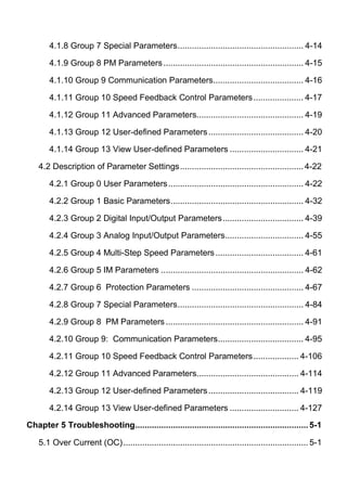
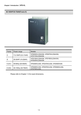
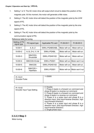
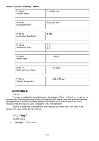
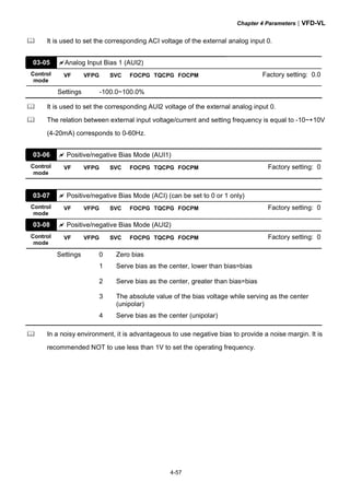
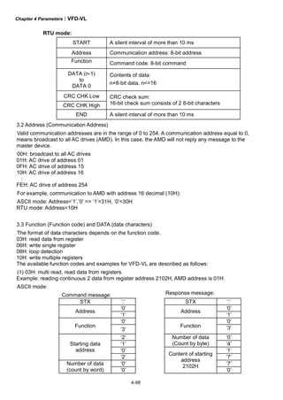
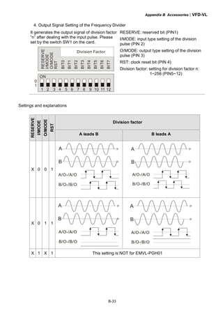
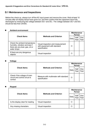
Step 2: place the 8 screws back in to secure the fixed plate 1 and fixed plate 2 (as shown in the
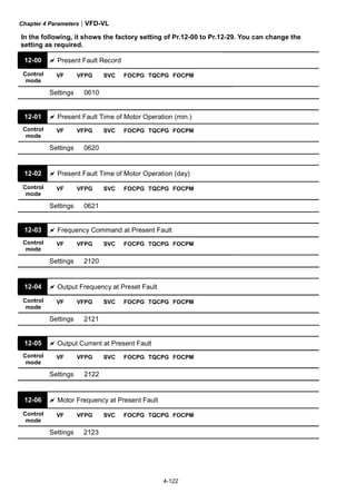
following figures) with the following torque.
Frame C: 14-17kgf-cm [12.2-14.8in-lbf]
Frame D: 20-25kgf-cm [17.4-21.7in-lbf]
Frame E: 20-25kgf-cm [17.4-21.7in-lbf]
1
2
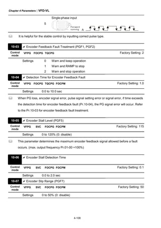
3
4
fixed plate 1
1
2
3
4
fixed plate 2
Step 3: Please notice that it doesn’t need to put those 8 screws shown in the following figures
back to the drive. Moreover, please make sure that these 2 different fixed plates are put in the
correct side as shown in the figures.
1
2
3
4
5
6
7
8](https://image.slidesharecdn.com/vfd-vlmen20111018-140613014943-phpapp01/85/Vfd-vl-m-en_20111018-21-320.jpg)

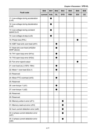
![Chapter 1 Introduction|VFD-VL
1-13
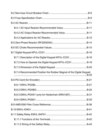
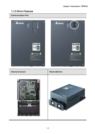
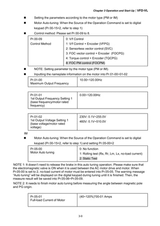
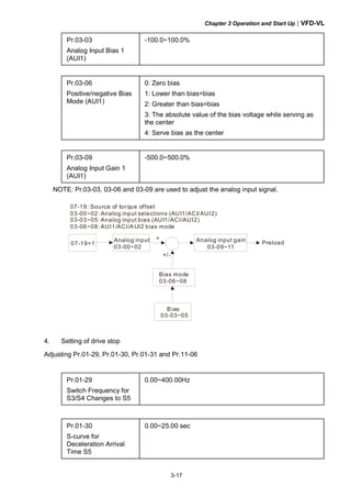
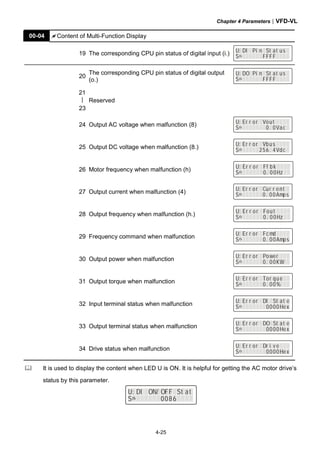
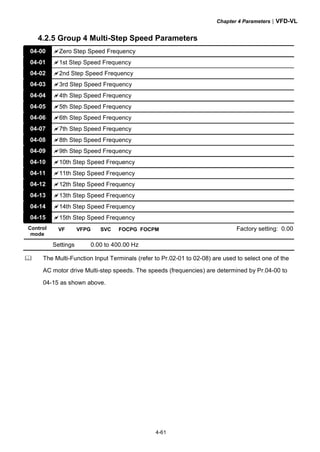
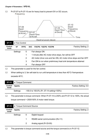
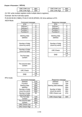
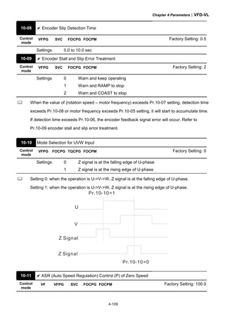
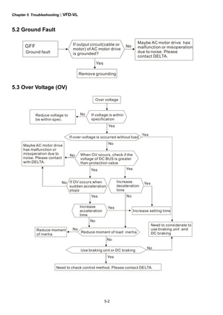
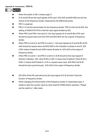
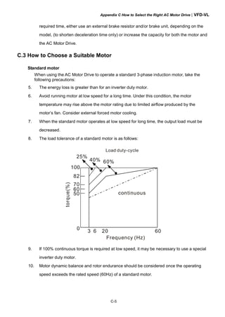
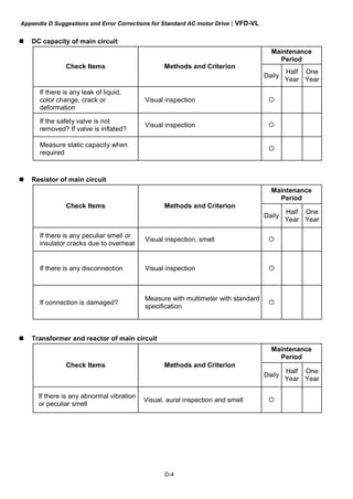
1.3 Dimensions
Frame C
Check to be s ure that t he voltage of the main AC power
supply satis fies t he rat ed voltage of the I nverter.
Do not c onnect AC power t o output terminals U/T1,
V/T2 and W/T3.
Risk of electrical s hock. Wait 10 m inutes after removing
power before servic ing.
Use proper grounding techniques.
Read the us er manual before operation.
WARNING
W
W1
H
H2H1
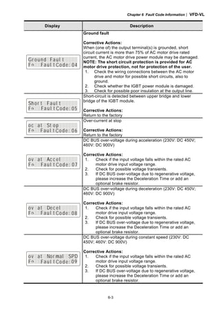
H3
D
1 32
Unit: mm [inch]
Frame W W1 H H1 H2 H3 D Ø Ø1 Ø2 Ø3
C
235
[9.25]
204
[8.03]
350
[13.78]
337
[13.27]
320
[12.60]
-
136
[5.35]
6.5
[0.26]
-
34
[1.34]
22
[0.87]
NOTE
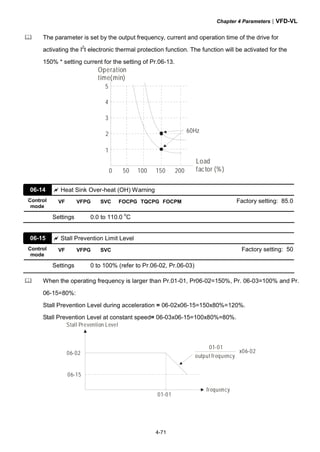
Frame C: VFD055VL23A/43A, VFD075VL23A/43A, VFD110VL23A/43A](https://image.slidesharecdn.com/vfd-vlmen20111018-140613014943-phpapp01/85/Vfd-vl-m-en_20111018-24-320.jpg)
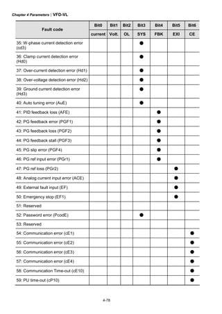
![Chapter 1 Introduction|VFD-VL
1-14
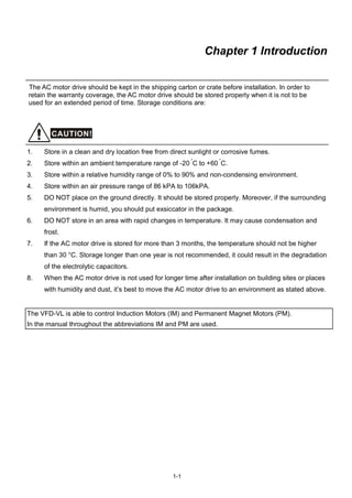
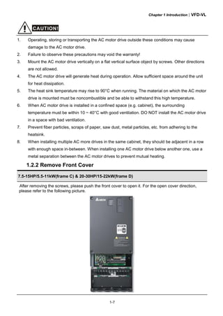
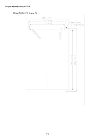
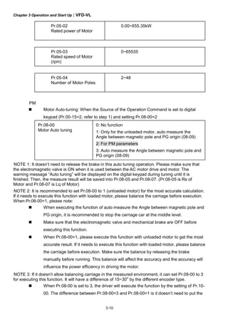
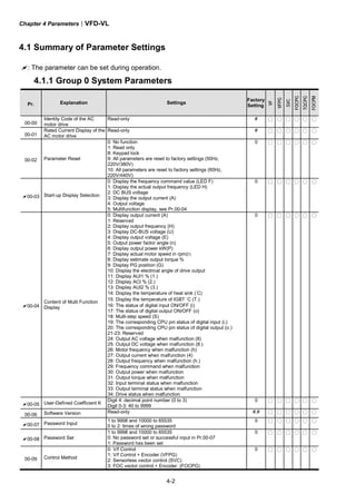
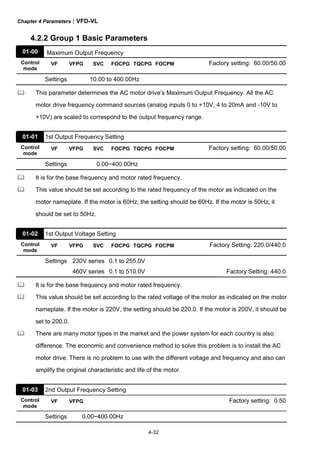
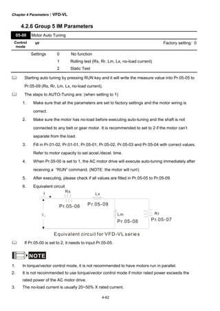
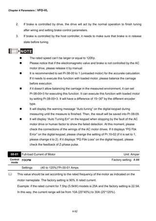
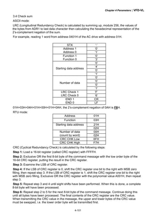
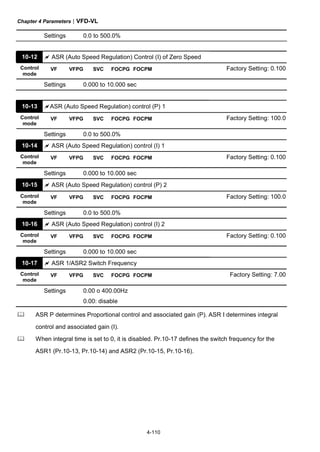
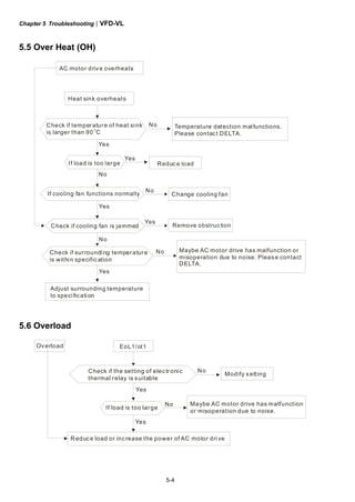
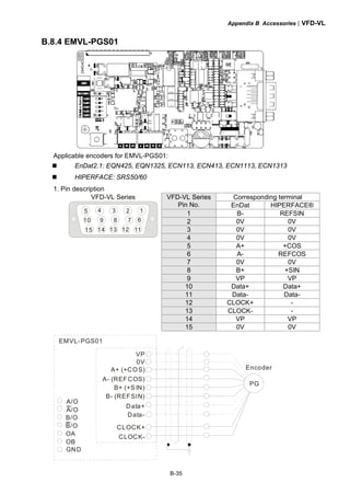
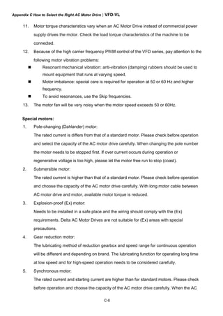
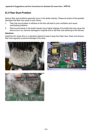
Frame D
Check to be s ure that t he voltage of the main AC power
supply satis fies t he rat ed voltage of the I nverter.
Do not c onnect AC power t o output terminals U/T1,
V/T2 and W/T3.
Risk of electrical s hock. Wait 10 m inutes after removing
power before servic ing.
Use proper grounding techniques.
Read the us er manual before operation.
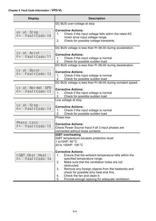
WARNING
W
W1
H
H2H1
H3
D
1 32
Unit: mm [inch]
Frame W W1 H H1 H2 H3 D Ø Ø1 Ø2 Ø3
D
255.0
[10.04]
226.0
[8.90]
403.8
[15.90]
384.0
[15.12]
360.0
[14.17]
21.9
[0.86]
168.0
[6.61]
8.5
[0.33]
44
[1.73]
34
[1.34]
22
[0.87]
NOTE
Frame D: VFD150VL23A/43A, VFD185VL23A/43A, VFD220VL23A/43A](https://image.slidesharecdn.com/vfd-vlmen20111018-140613014943-phpapp01/85/Vfd-vl-m-en_20111018-25-320.jpg)
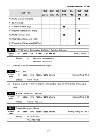
![Chapter 1 Introduction|VFD-VL
1-15
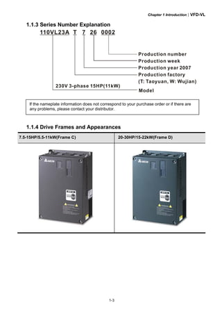
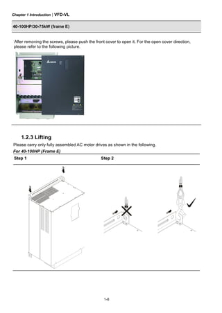
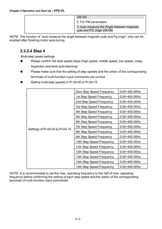
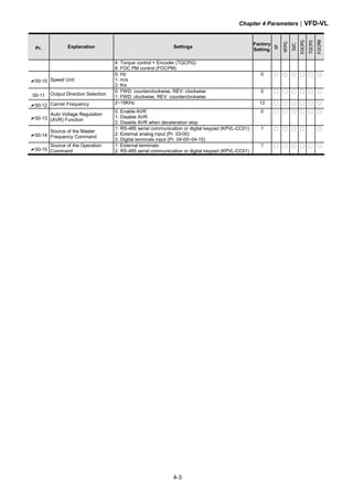
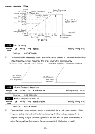
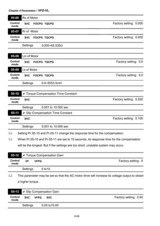
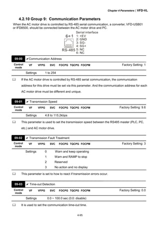
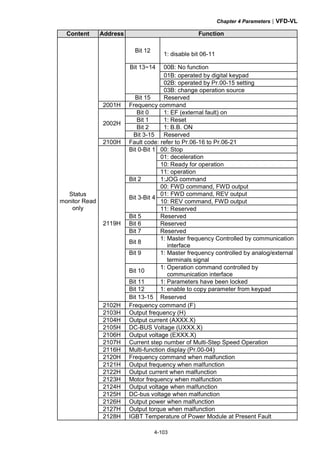
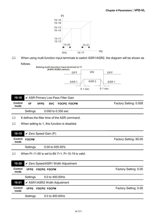
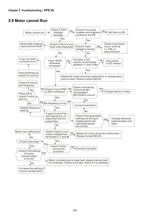
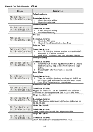
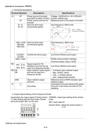
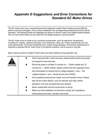
Frame E
W1
W D
H1
H2
S2
H
D1
S1
D2S3
Unit: mm [inch]
Frame W W1 H H1 H2 D D1 D2 S1 S2 S3
E1
370.0
[14.57]
335.0
[13.19]
-
589.0
[23.19]
560.0
[22.05]
260.0
[10.24]
132.5
[5.22]
18.0
[0.71]
13.0
[0.51]
13.0
[0.51]
18.0
[0.71]
E2
370.0
[14.57]
335.0
[13.19]
595.0
[23.43]
589.0
[23.19]
560.0
[22.05]
260.0
[10.24]
132.5
[5.22]
18.0
[0.71]
13.0
[0.51]
13.0
[0.51]
18.0
[0.71]
NOTE
Frame E1: VFD300VL43A, VFD370VL43A, VFD450VL43A
Frame E2: VFD300VL23A, VFD370VL23A, VFD550VL43A, VFD750VL43A](https://image.slidesharecdn.com/vfd-vlmen20111018-140613014943-phpapp01/85/Vfd-vl-m-en_20111018-26-320.jpg)


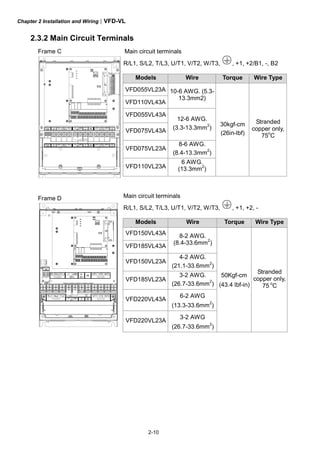
![Chapter 2 Installation and Wiring|VFD-VL
2-9
time to avoid nuisance tripping. For the specific GFCI of the AC motor drive, please
select a current sensor with sensitivity of 30mA or above.
Do NOT run/stop AC motor drives by turning the power ON/OFF. Run/stop AC motor
drives by RUN/STOP command via control terminals or keypad. If you still need to
run/stop AC drives by turning power ON/OFF, it is recommended to do so only
ONCE per hour.
Do NOT connect 3-phase models to a 1-phase power source.
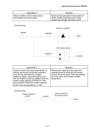
Output terminals for main circuit (U, V, W)
When it needs to install the filter at the output side of terminals U/T1, V/T2, W/T3 on
the AC motor drive. Please use inductance filter. Do not use phase-compensation
capacitors or L-C (Inductance-Capacitance) or R-C (Resistance-Capacitance),
unless approved by Delta.
DO NOT connect phase-compensation capacitors or surge absorbers at the output
terminals of AC motor drives.
Use well-insulated motor, suitable for inverter operation.
Terminals [+1, +2] for connecting DC reactor, terminals [+1, +2/B1] for connecting brake
resistor
+1
Jumper
DC reactor
To improve power factor and reduce harmonics connect a DC reactor between
terminals [+1, +2/B1]. Please remove the jumper before connecting the DC reactor.
Models above 22kW don’t have a built-in brake chopper. Please connect an external
optional brake resistor.
When not used, please leave the terminals [+2/B1, -] open.
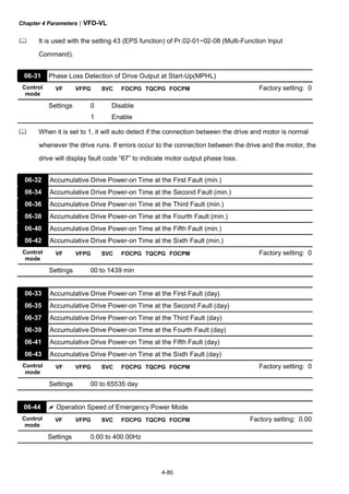
Short-circuiting [B2] or [-] to [+2/B1] can damage the AC motor drive.](https://image.slidesharecdn.com/vfd-vlmen20111018-140613014943-phpapp01/85/Vfd-vl-m-en_20111018-36-320.jpg)


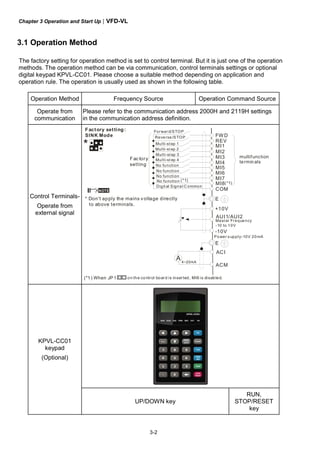

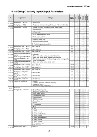
![Chapter 3 Operation and Start Up|VFD-VL
3-4
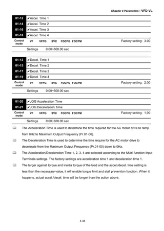
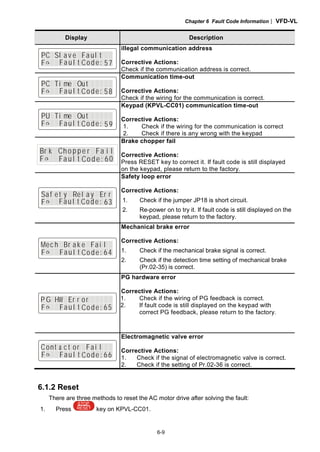
3.3 Auto-tuning Operations
3.3.1 Flow Chart
IM
PM
Selection of speed
feedback card
EMVL-PGABL
EMVL-PGABO
EMVL-PGH01
EMVL-PGS01
Step 1 Basic parameter settings
Source of the Master
Frequency Command
Pr.00-14
Setting all parameters
to factory setting
Pr.00-02
Source of the
Operation Command
Pr.00-15
MI/MO terminals Settings
Pr.02-01~02-08
Pr.02-13~02-22
Control Mode Selection
Pr.00-09
Motor type
[PM/IM]
Setting the related
information of IM motor
Pr. 01-00~01-02
Pr.05-01~05-04
Setting the related
information of PM motor
Pr.01-00~01-02
Pr.08-01~08-04
IM Motor Auto-tuning
Pr.05-00
PM Motor Auto-tuning
Pr.08-00
Step 2 Encoder settings
Detection of the HOME
position of Encoder
1. using digital keypad
2. using external terminals
Setting Encodertype
Pr.10-01~10-02
Encoder selection
Pr.10-00
Step 4 Multi-step speed settings
Setting speed, accel/decel. time and S curve
Pr.04-00~04-15, Pr.01-12~01-19, Pr.01-24~01-30
Step 5 Inertia measurement
Trial run
Smooth test
Pr.11-00 bit0=1
Pr.11-05~11-08
1. tuning as start-up
2. tuning as stop
Step 6 Elevator tuning
Angle between magnetic field and PG origin
Pr.08-09
Step 3 Motor Tunning
Step 6 Trial run
Inertia measurement
Pr.11-01~11-05, Pr.11-14~11-15](https://image.slidesharecdn.com/vfd-vlmen20111018-140613014943-phpapp01/85/Vfd-vl-m-en_20111018-45-320.jpg)


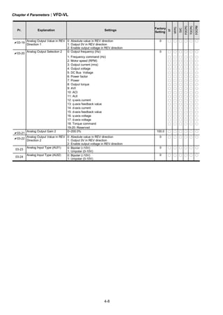


![Appendix B Accessories|VFD-VL
B-8
B.1.3 Dimensions for Brake Unit
VFDB2015, VFDB2022, VFDB4030, VFDB4045
(Dimensions are in millimeter[inch])
80.0 [3.15]
121.0 [4.76]
189.5[7.46]
200.0[7.87]
130.0 [5.12]
R3.3 [R0.13]
ACT.
YELLOW
CHARGE
GREEN
ERR.
RED](https://image.slidesharecdn.com/vfd-vlmen20111018-140613014943-phpapp01/85/Vfd-vl-m-en_20111018-219-320.jpg)


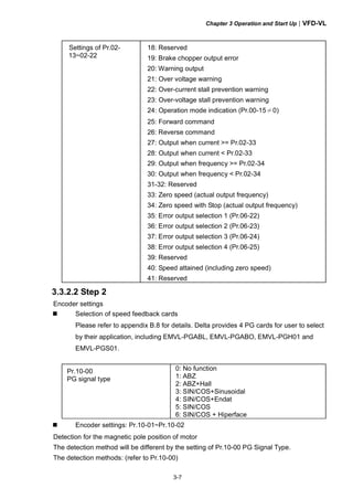
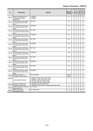
![Appendix B Accessories|VFD-VL
B-20
B.7.3 Dimension of the Digital Keypad
Unit: mm [inch]
B.7.4 Recommended Position the Rubber Magnet of the Digital
Keypad
This rubber magnet is shipped with the digital keypad. Users can adhere to anywhere of
the back of the digital keypad to stick on the case of the AC motor drive. Please don’t stick
on the communication port to prevent reducing magnetic force.
LABEL
JOG
FWD
R EV
RUN
PU
STO P
R ESET
PRO G
D ATA
MODE
7 8 9
654
1 2
0.
3
+/-
KPVL-CC01
P UEX TRE VFWDJO GSTOPRU N
rubber
magnet
rubber
magnet](https://image.slidesharecdn.com/vfd-vlmen20111018-140613014943-phpapp01/85/Vfd-vl-m-en_20111018-231-320.jpg)


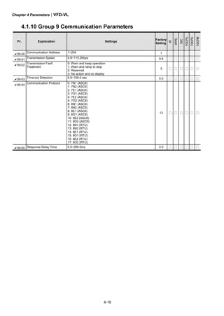
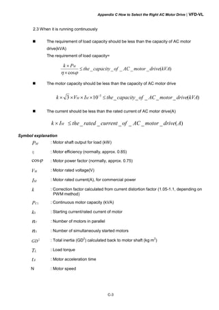
![Appendix C How to Select the Right AC Motor Drive|VFD-VL
C-2
C.1 Capacity Formulas
1. When one AC motor drive operates one motor
The starting capacity should be less than 1.5x rated capacity of AC motor drive
The starting capacity=
)(_____5.1
375cos973
2
kVAdrivemotorACofcapacitythe
t
NGD
T
Nk
A
L ×≤⎟⎟
⎠
⎞
⎜⎜
⎝
⎛
×+
××
×
ϕη
2. When one AC motor drive operates more than one motor
2.1 The starting capacity should be less than the rated capacity of AC motor drive
Acceleration time ≦60 seconds
The starting capacity=
( )[ ] ( ) )(_____5.11
cos
111 kVAdrivemotorACofcapacitythek
n
n
Pknn
Nk
sCss
T
s
T ×≤+=+
×
×
⎥
⎥
⎥
⎦
⎤
⎢
⎢
⎢
⎣
⎡
−−
ϕη
Acceleration time ≧60 seconds
The starting capacity=
( )[ ] ( ) )(_____1
cos
111 kVAdrivemotorACofcapacitythek
n
n
Pknn
Nk
sCss
T
s
T ≤+=+
×
×
⎥
⎥
⎥
⎦
⎤
⎢
⎢
⎢
⎣
⎡
−−
ϕη
2.2 The current should be less than the rated current of AC motor drive(A)
Acceleration time ≦60 seconds
)(______5.111 AdrivemotorACofcurrentratedthekn
nIn SM
T
S
T ×≤++ ⎥
⎦
⎤
⎢
⎣
⎡
⎟
⎠
⎞⎜
⎝
⎛ −
Acceleration time ≧60 seconds
)(______11 AdrivemotorACofcurrentratedthekn
nIn SM
T
S
T ≤++ ⎥
⎦
⎤
⎢
⎣
⎡
⎟
⎠
⎞⎜
⎝
⎛ −](https://image.slidesharecdn.com/vfd-vlmen20111018-140613014943-phpapp01/85/Vfd-vl-m-en_20111018-257-320.jpg)


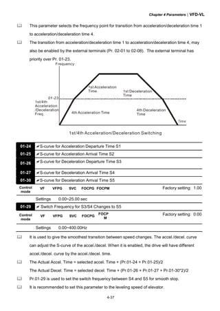
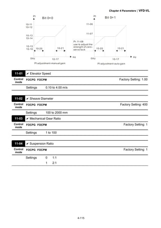
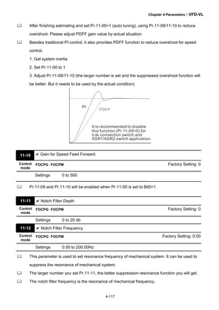
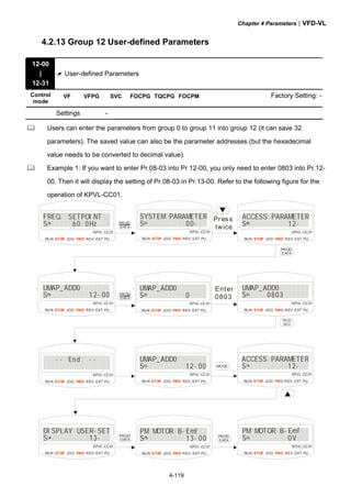
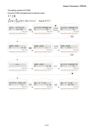
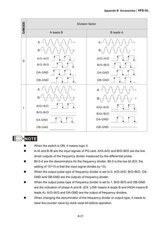
This document provides instructions for installing and operating a DELTA VFD-VL Series AC motor drive. It contains safety guidelines that must be followed to prevent injury and damage. The drive uses high-quality components and microprocessor technology. The manual covers installation, wiring, parameter settings, troubleshooting and maintenance. It is important to only allow qualified personnel to work with the drive and always follow the safety warnings.


![Ct2000 pro plus_manual_english[1]](https://cdn.slidesharecdn.com/ss_thumbnails/ct2000proplusmanualenglish1-140613213527-phpapp02-thumbnail.jpg?width=640&height=640&fit=bounds)


![Ct2000 es manual_english_version_1[1].0](https://cdn.slidesharecdn.com/ss_thumbnails/ct2000esmanualenglishversion11-140613213448-phpapp01-thumbnail.jpg?width=640&height=640&fit=bounds)


