Downloaded 10 times


![Chapter 1 Introduction|
Revision May 2008, ME14, SW V3.04 1-7
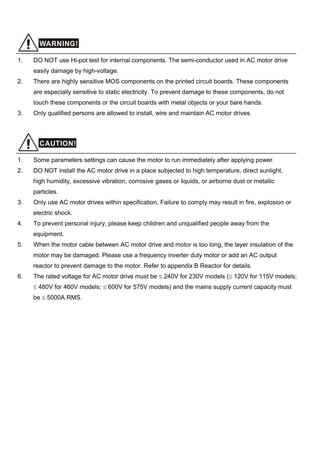
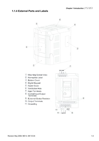
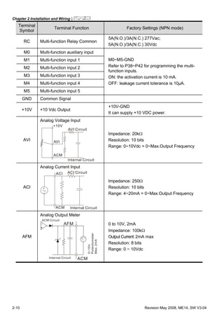
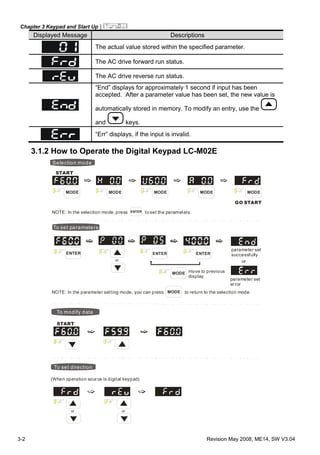
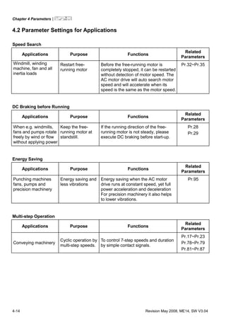
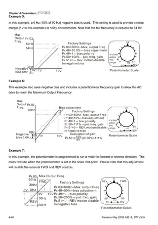
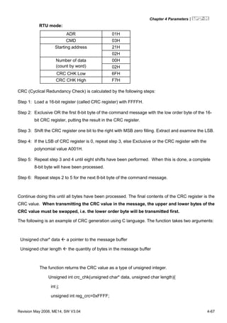
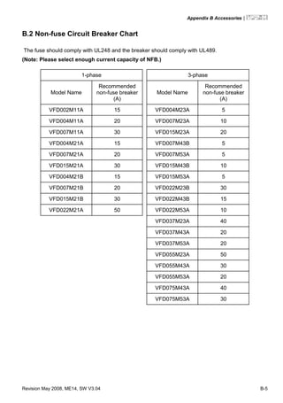
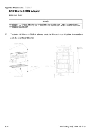
1.3 Dimensions
H
DD1
H1
W1
W
H2
Unit: mm [inch]
Model Name W W1 H H1 H2 D D1
VFD004M21A/23A,
VFD007M21A/23A,
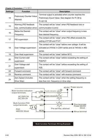
VFD015M21A/23A
85.0
[3.35]
74.0
[2.91]
141.5
[5.57]
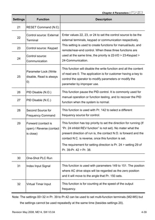
130.5
[5.14]
10.0
[0.39]
113.0
[4.45]
10.0
[0.39]
VFD002M11A,
VFD004M11A/21B,
VFD007M11A/21B/43B/53A,
VFD015M21B/43B/53A,
VFD022M23B/43B/53A
100.0
[3.94]
89.0
[3.50]
151.0
[5.94]
140.0
[5.51]
10.0
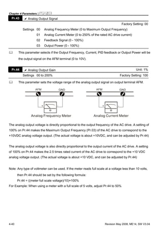
[0.39]
116.5
[4.59]
10.5
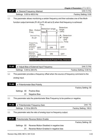
[0.41]
D1 D
H2H
H1
W
W1
Unit: mm [inch]
Model Name W W1 H H1 H2 D D1
VFD022M21A,
VFD037M23A/43A/53A,
VFD055M23A/43A/53A,
VFD075M43A/53A
125.0
[4.92]
110.0
[4.33]
220.0
[8.66]
205.0
[8.07]
15.0
[0.59]
166.3
[6.55]
8.2
[0.32]](https://image.slidesharecdn.com/vfdmen20100514-140613013403-phpapp01/85/Vfd-m-en_20100514-16-320.jpg)


![Chapter 2 Installation and Wiring|
Revision May 2008, ME14, SW V3.04 2-7
Please use voltage and current within the regulation shown in Appendix A.
When using a GFCI (Ground Fault Circuit Interrupter), select a current sensor with sensitivity of
200mA, and not less than 0.1-second detection time to avoid nuisance tripping.
Do NOT run/stop AC motor drives by turning the power ON/OFF. Run/stop AC motor drives by
RUN/STOP command via control terminals or keypad. If you still need to run/stop AC drives by
turning power ON/OFF, it is recommended to do so only ONCE per hour.
Do NOT connect 3-phase models to a 1-phase power source.
Output terminals for main circuit (U, V, W)
When it needs to install the filter at the output side of terminals U/T1, V/T2, W/T3 on the AC
motor drive. Please use inductance filter. Do not use phase-compensation capacitors or L-C
(Inductance-Capacitance) or R-C (Resistance-Capacitance), unless approved by Delta.
DO NOT connect phase-compensation capacitors or surge absorbers at the output terminals of
AC motor drives.
Use well-insulated motor, suitable for inverter operation.
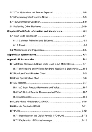
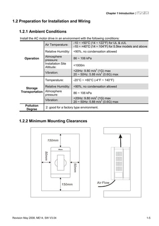
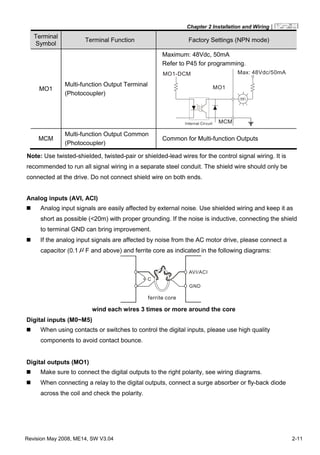
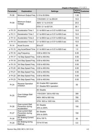
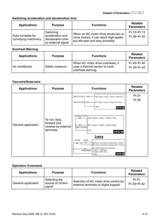
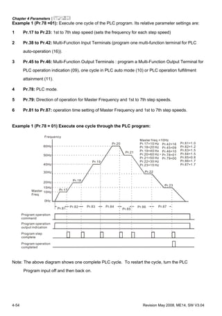
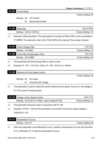
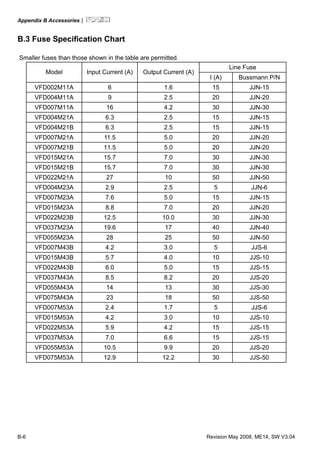
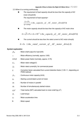
Terminals [B1, B2] for connecting external brake unit
B2
BR
Brake Resistor(optional)
Refer to Appendix B for the use of
special brake resistor
Connect a brake resistor or brake unit in applications with frequent deceleration ramps, short
deceleration time, too low braking torque or requiring increased braking torque.
The AC motor drive has a built-in brake chopper, you can connect the external brake resistor to
the terminals [B1, B2] when needed.
When not used, please leave the terminals [B1, B2] open.](https://image.slidesharecdn.com/vfdmen20100514-140613013403-phpapp01/85/Vfd-m-en_20100514-24-320.jpg)

![Chapter 3 Keypad and Start Up|
Revision May 2008, ME14, SW V3.04 3-3
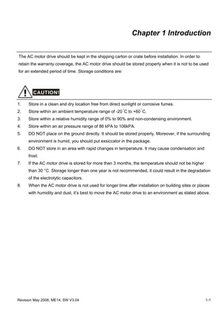
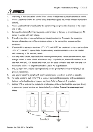
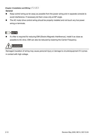
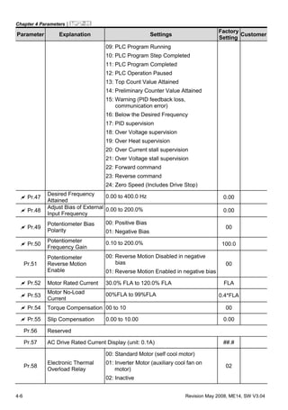
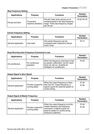
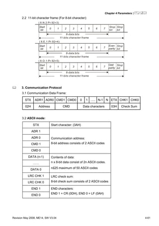
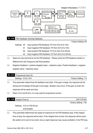
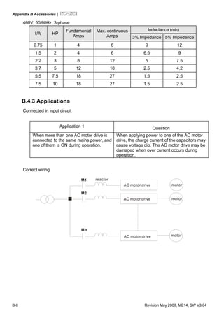
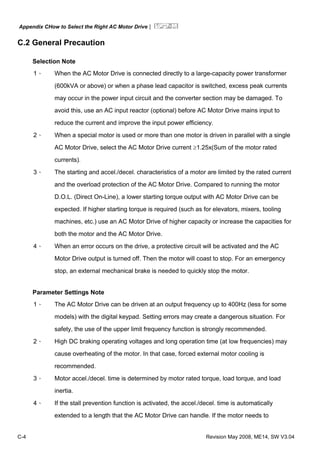
3.1.3 LC-M02E
Unit: mm [inch]
Reference Table for the 7-segment LED Display of the Digital Keypad
Digit 0 1 2 3 4 5 6 7 8 9
LED
Display
English
alphabet
A b Cc d E F G Hh I Jj
LED
Display
English
alphabet
K L n Oo P q r S Tt U
LED
Display
English
alphabet
v Y Z
LED
Display](https://image.slidesharecdn.com/vfdmen20100514-140613013403-phpapp01/85/Vfd-m-en_20100514-32-320.jpg)
![Chapter 3 Keypad and Start Up|
3-4 Revision May 2008, ME14, SW V3.04
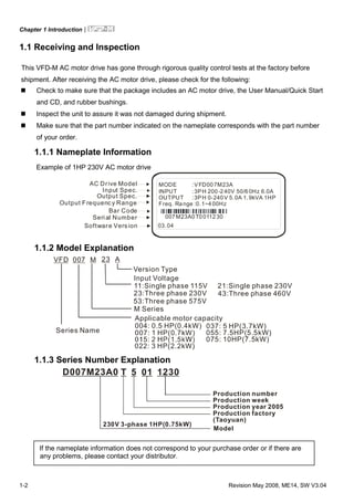
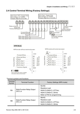
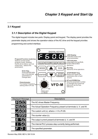
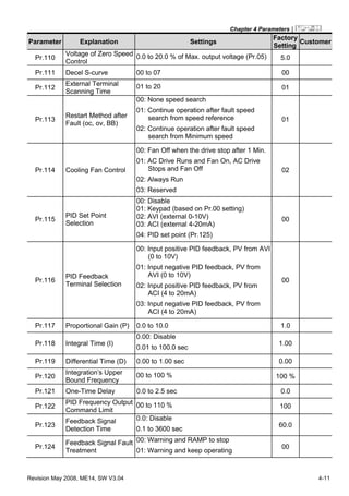
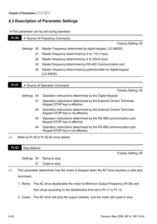
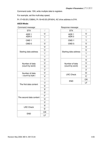
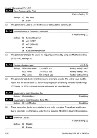
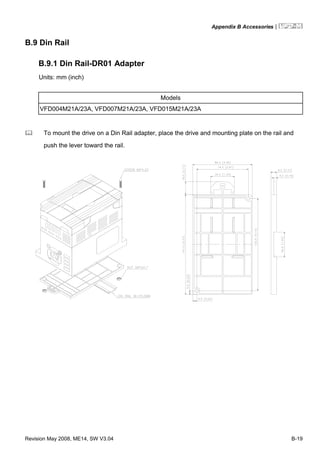
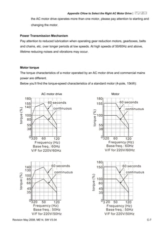
Digital Keypad – Mounting Panel A
Unit: mm [inch]
Digital Keypad – Mounting Panel B
Unit: mm [inch]](https://image.slidesharecdn.com/vfdmen20100514-140613013403-phpapp01/85/Vfd-m-en_20100514-33-320.jpg)


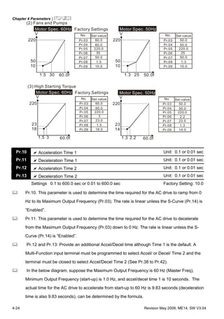


![Chapter 4 Parameters|
4-70 Revision May 2008, ME14, SW V3.04
Content Address Functions
2106H Output Voltage E (XXX.X)
2107H Step number of Multi-Step Speed Operation (step)
2108H Time of PLC Operation (sec)
2109H Value of External Trigger (count)
210AH The Correspondent Value of Power Factor (XXX.X)
210BH Pr.65 X Low word of H (XXX.XX)
210CH Pr.65 X High word of H (XXX.XX)
210DH AC Drive Temperature (XXX.X)
210EH PID Feedback Signal (XXX.XX)
210FH PID Target Value (XXX.XX)
2110H AC Drive Mode Type Information
3.7 Communication program of PC:
The following is a simple example of how to write a communication program for Modbus ASCII
mode on a PC by C language.
#include<stdio.h>
#include<dos.h>
#include<conio.h>
#include<process.h>
#define PORT 0x03F8 /* the address of COM1 */
/* the address offset value relative to COM1 */
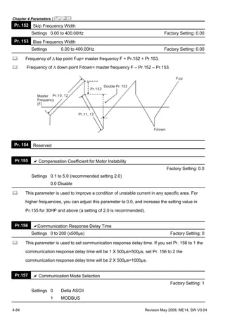
#define THR 0x0000
#define RDR 0x0000
#define BRDL 0x0000
#define IER 0x0001
#define BRDH 0x0001
#define LCR 0x0003
#define MCR 0x0004
#define LSR 0x0005
#define MSR 0x0006
unsigned char rdat[60];
/* read 2 data from address 2102H of AC drive with address 1 */
unsigned char tdat[60]={':','0','1','0','3','2','1','0',’2', '0','0','0','2','D','7','r','n'};](https://image.slidesharecdn.com/vfdmen20100514-140613013403-phpapp01/85/Vfd-m-en_20100514-105-320.jpg)
![Chapter 4 Parameters|
Revision May 2008, ME14, SW V3.04 4-71
void main(){
int i;
outportb(PORT+MCR,0x08); /* interrupt enable */
outportb(PORT+IER,0x01); /* interrupt as data in */
outportb(PORT+LCR,(inportb(PORT+LCR) | 0x80));
/* the BRDL/BRDH can be access as LCR.b7==1 */
outportb(PORT+BRDL,12); /* set baudrate=9600, 12=115200/9600*/
outportb(PORT+BRDH,0x00);
outportb(PORT+LCR,0x06); /* set protocol, <7,N,2>=06H
<7,E,1>=1AH, <7,O,1>=0AH
<8,N,2>=07H, <8,E,1>=1BH
<8,O,1>=0BH */
for(i=0;i<=16;i++){
while(!(inportb(PORT+LSR) & 0x20)); /* wait until THR empty */
outportb(PORT+THR,tdat[i]); /* send data to THR */
}
i=0;
while(!kbhit()){
if(inportb(PORT+LSR) & 0x01){ /* b0==1, read data ready */
rdat[i++]=inportb(PORT+RDR); /* read data form RDR */
} } }](https://image.slidesharecdn.com/vfdmen20100514-140613013403-phpapp01/85/Vfd-m-en_20100514-106-320.jpg)


![Appendix CHow to Select the Right AC Motor Drive|
C-2 Revision May 2008, ME14, SW V3.04
C.1 Capacity Formulas
1. When one AC motor drive operates one motor
The starting capacity should be less than 1.5x rated capacity of AC motor drive
The starting capacity=
)(_____5.1
375cos973
2
kVAdrivemotorACofcapacitythe
t
NGD
T
Nk
A
L ×≤⎟⎟
⎠
⎞
⎜⎜
⎝
⎛
×+
××
×
ϕη
2. When one AC motor drive operates more than one motor
2.1 The starting capacity should be less than the rated capacity of AC motor drive
Acceleration time ≦60 seconds
The starting capacity=
( )[ ] ( ) )(_____5.11
cos
111 kVAdrivemotorACofcapacitythek
n
n
Pknn
Nk
sCss
T
s
T ×≤+=+
×
×
⎥
⎥
⎥
⎦
⎤
⎢
⎢
⎢
⎣
⎡
−−
ϕη
Acceleration time ≧60 seconds
The starting capacity=
( )[ ] ( ) )(_____1
cos
111 kVAdrivemotorACofcapacitythek
n
n
Pknn
Nk
sCss
T
s
T ≤+=+
×
×
⎥
⎥
⎥
⎦
⎤
⎢
⎢
⎢
⎣
⎡
−−
ϕη
2.2 The current should be less than the rated current of AC motor drive(A)
Acceleration time ≦60 seconds
)(______5.111 AdrivemotorACofcurrentratedthekn
nIn SM
T
S
T ×≤++ ⎥
⎦
⎤
⎢
⎣
⎡
⎟
⎠
⎞⎜
⎝
⎛ −
Acceleration time ≧60 seconds
)(______11 AdrivemotorACofcurrentratedthekn
nIn SM
T
S
T ≤++ ⎥
⎦
⎤
⎢
⎣
⎡
⎟
⎠
⎞⎜
⎝
⎛ −](https://image.slidesharecdn.com/vfdmen20100514-140613013403-phpapp01/85/Vfd-m-en_20100514-167-320.jpg)


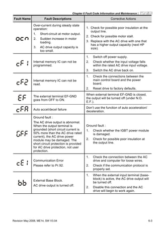
This document provides safety guidelines and instructions for installing, operating, and maintaining DELTA's VFD-M Series AC motor drive. It contains warnings about disconnecting power before wiring, residual high voltages in capacitors, and only allowing qualified personnel to perform tasks. The document consists of preface, table of contents, and 6 chapters that cover introduction and inspection, installation, keypad operation, parameter settings, troubleshooting, and maintenance. It also includes appendices with specifications and information on accessories like brake resistors.


![Ct2000 pro plus_manual_english[1]](https://cdn.slidesharecdn.com/ss_thumbnails/ct2000proplusmanualenglish1-140613213527-phpapp02-thumbnail.jpg?width=640&height=640&fit=bounds)


![Ct2000 es manual_english_version_1[1].0](https://cdn.slidesharecdn.com/ss_thumbnails/ct2000esmanualenglishversion11-140613213448-phpapp01-thumbnail.jpg?width=640&height=640&fit=bounds)


