Download to read offline


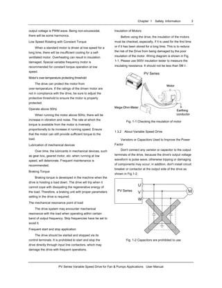

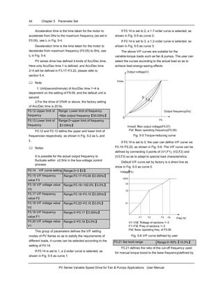

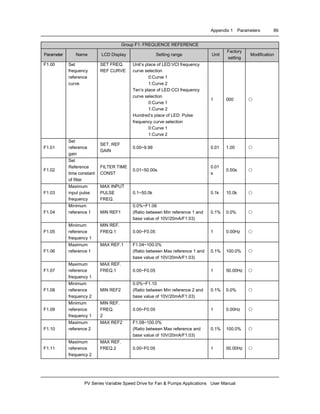
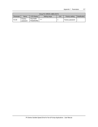

![Appendix 2 Communication Protocol 129
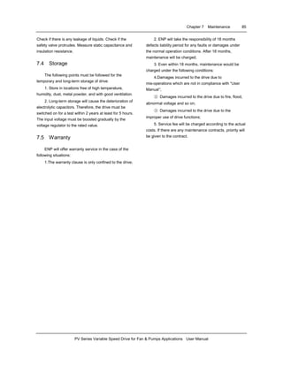
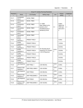
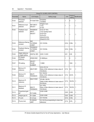
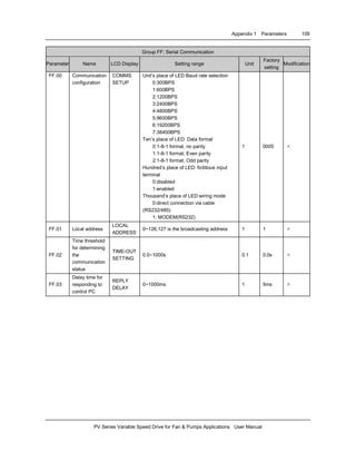
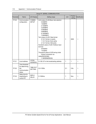
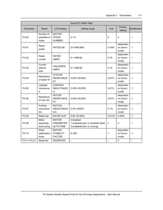
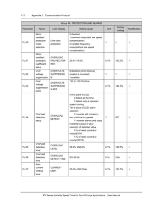
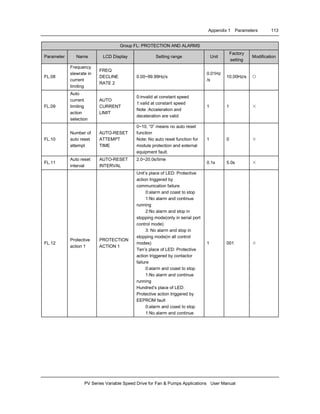
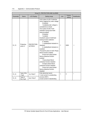
PV Series Variable Speed Drive for Fan & Pumps Applications User Manual
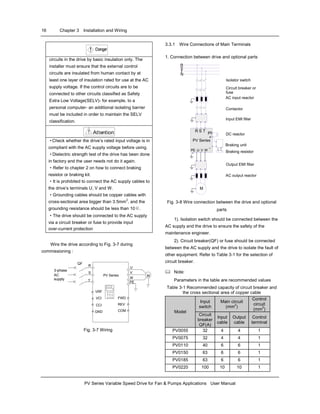
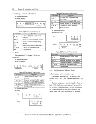
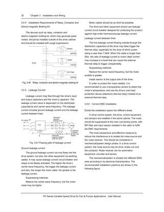
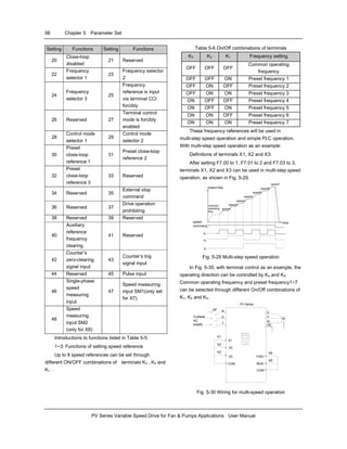
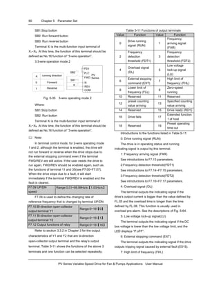
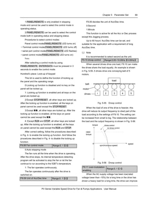
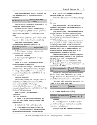
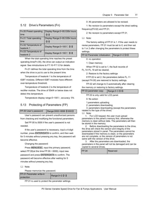
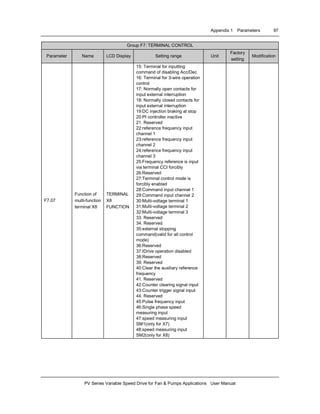
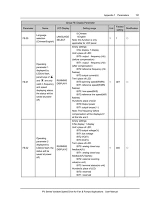
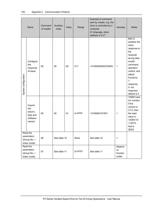
2) Example (Turbo C 2.0): Send the command of running the drive, stopping the drive and setting the frequency (need to
set F0.00 to 2, and set F0.03 to 2 first.)
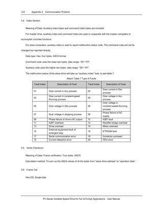
#include <dos.h>
#include <bios.h>
#include <conio.h>
#include <stdio.h>
#define COM1 0 /*serial port 1*/
#define COM2 1 /*serial port 2*/
#define SET_COMPARA 0 /* To set the parameters of communication ports */
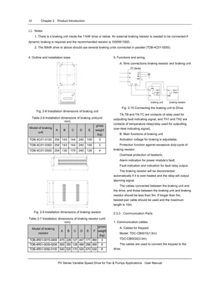
#define DEFAULT_BAUD 0xE3 /*8-N-1,9600bps*/
#define PORT_ADDR 0x3F8 /* Address of serial port is 13F8H*/
#define delaytime 100 /*100ms delay time */
char run_drive[20]="~010200000183r"; /* Command of running the drive */
char stop_drive[20]="~01020007018Ar"; /* Command of stopping the drive*/
void send_comd(char *sendstr,char *display_type); /* Send the command */
void checksum(char *sendstr,char result_sum[]); /*Calculate verify checksum*/
main()
{
char sum_of_cmd[5],buf[25]; /*store the string of 4-byte verify checksum */
char set_frequency[25]="010200010BB8"; /* set the running frequency at 30.00Hz */
bioscom(SET_COMPARA,DEFAULT_BAUD,COM1); /* set COM1, 8-N-1, 9600bps */
send_comd(run_drive,"HEX"); /* Send run command, display in HEX format */
printf("nPress anykey to set frequency to 30.00Hz ...");
while(!kbhit()); /* wait for pressing any key to input */
getchar(); /* get character */
checksum(set_frequency,sum_of_cmd); /* get the verify checksum of the sent command */
sprintf(buf,"~%s%sr",set_frequency,sum_of_cmd);
strcpy(set_frequency,buf); /* combine the sent frames */
send_comd(set_frequency,"HEX"); /* set to 30.00Hz, display in HEX format */
printf("nPress anykey to stop ...");
while(!kbhit()); /* wait for pressing any key to input */
send_comd(stop_drive,"ASCII"); /* Send stop command, display in ASCII format */
}
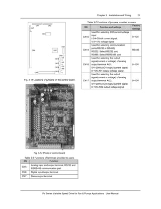
void send_comd(char *sendstr,char *display_type)
{
unsigned int i;
char buf[5]; /* used for character display */
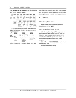
printf("nSend(%s):",display_type);
for(i=0;i<strlen(sendstr);i++){ /* send the frame command */
outportb(PORT_ADDR,sendstr[i]);
delay(delaytime); /* The delay time should ensure the command can be
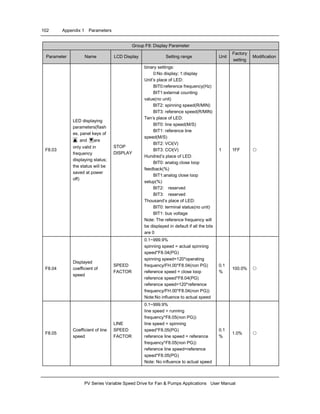
sent */](https://image.slidesharecdn.com/techpvseries-140613204721-phpapp02/85/Tech-pv-series-133-320.jpg)
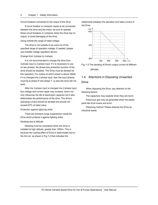
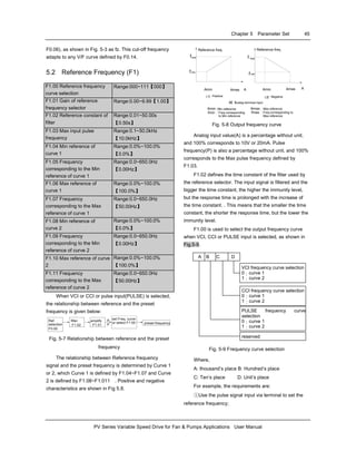
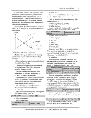
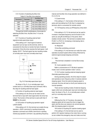
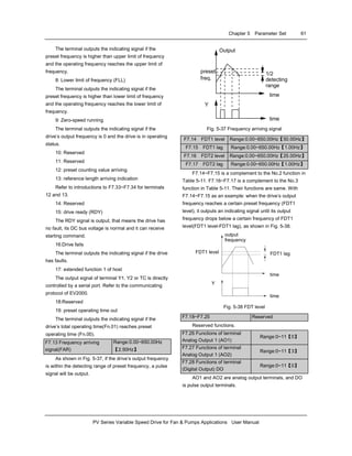
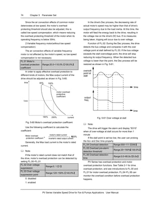
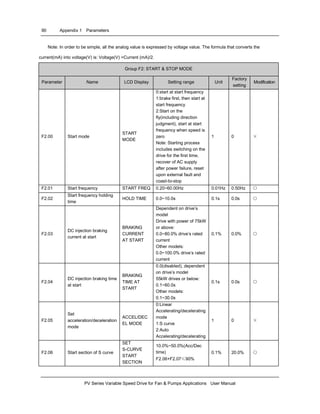
![130 Appendix 2 Communication Protocol
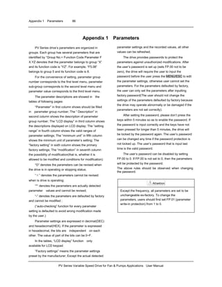
PV Series Variable Speed Drive for Fan & Pumps Applications User Manual
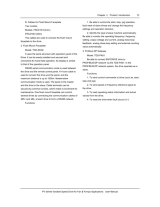
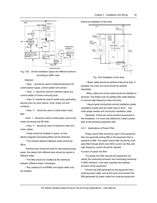
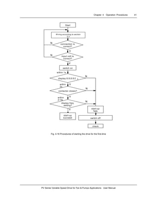
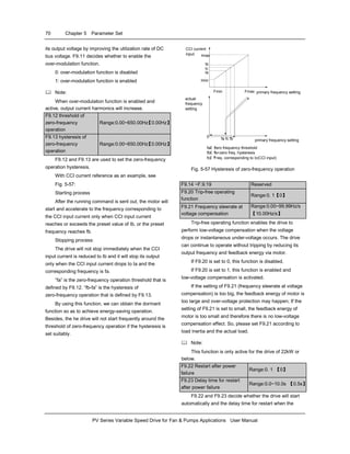
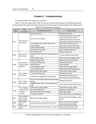
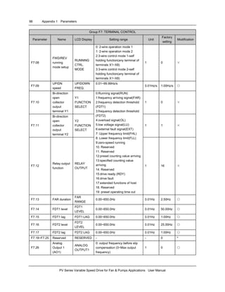
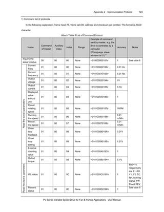
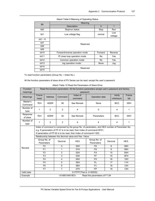
if(display_type[0]=='H') /* determine the display format */
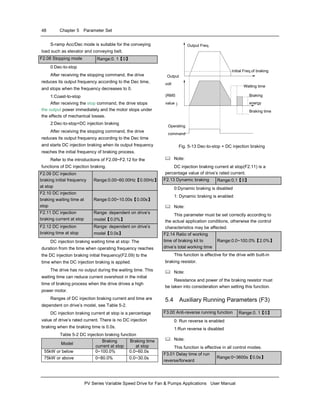
{printf("%02x ",sendstr[i]);} /* display in HEX format */
else{printf("%c",sendstr[i]);} /* display in ASCII format */
}
}
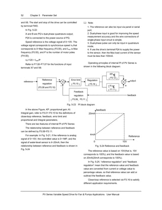
void checksum(char *sendstr,char result_sum[])
{
unsigned int i,sum=0;
static char sum_string[5]; /* calculate the sum of all the characters */
for(i=0;i<strlen(sendstr);i++)sum+=(unsigned int)sendstr[i];
sprintf(sum_string,"%04x",sum);
for(i=0;i<4;i++)
result_sum[i]=toupper(sum_string[i]); /* convert into capital letters */
result_sum[i]=0x0; /* end of string */
} /*result_sum return ASCII string of Verify checksum */](https://image.slidesharecdn.com/techpvseries-140613204721-phpapp02/85/Tech-pv-series-134-320.jpg)

This document is a user manual for the PV Series Variable Speed Drive. It provides information on installation, wiring, parameter settings, troubleshooting and maintenance of the drive. Chapter 1 discusses important safety information for installing and using the drive properly. Chapter 2 provides product specifications and details about the drive's components, ratings and optional parts. The remaining chapters cover installation and wiring, operation procedures, parameter settings, troubleshooting and maintenance.


![Ct2000 pro plus_manual_english[1]](https://cdn.slidesharecdn.com/ss_thumbnails/ct2000proplusmanualenglish1-140613213527-phpapp02-thumbnail.jpg?width=640&height=640&fit=bounds)


![Ct2000 es manual_english_version_1[1].0](https://cdn.slidesharecdn.com/ss_thumbnails/ct2000esmanualenglishversion11-140613213448-phpapp01-thumbnail.jpg?width=640&height=640&fit=bounds)


