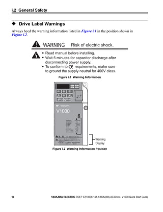
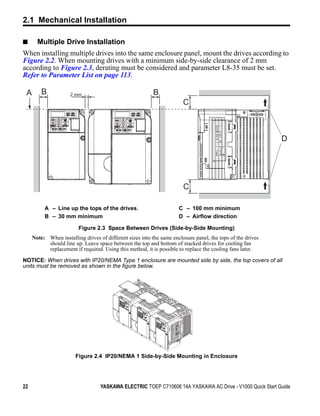
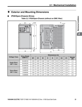
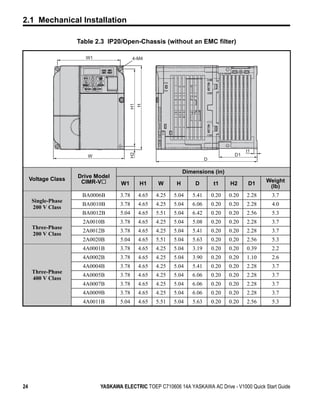
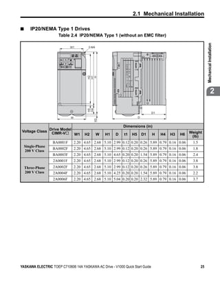
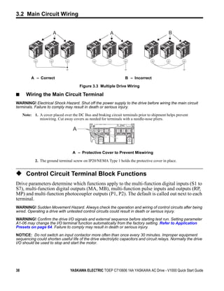
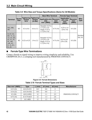
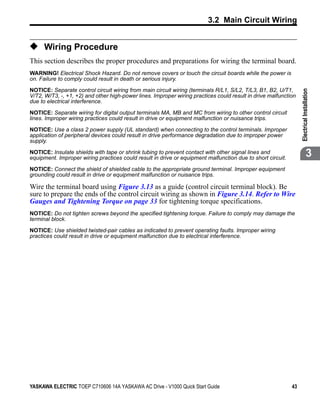
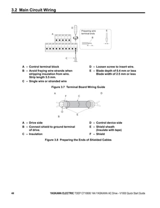
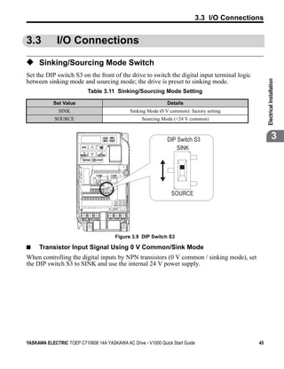
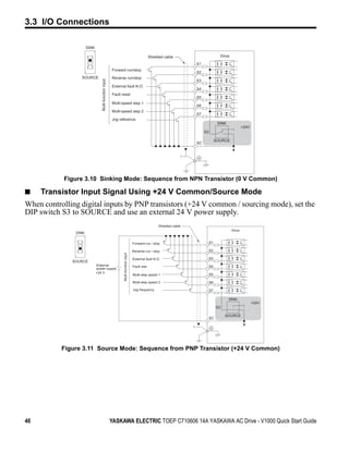
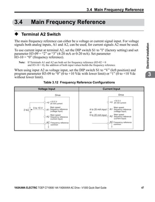
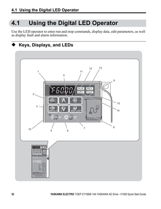
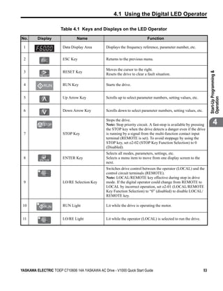
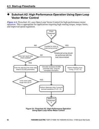
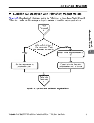
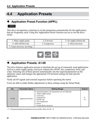
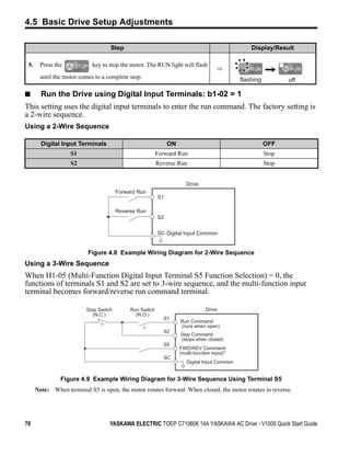
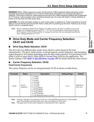
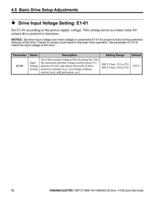
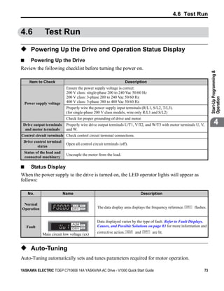
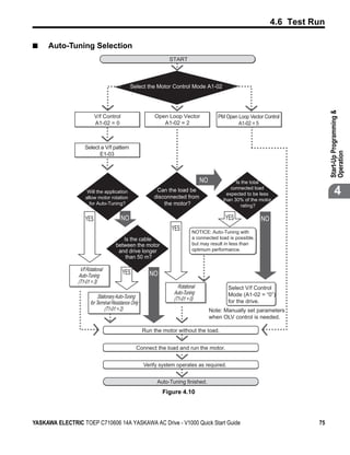
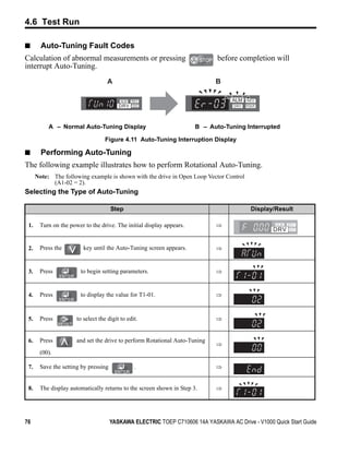
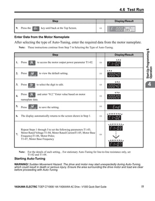
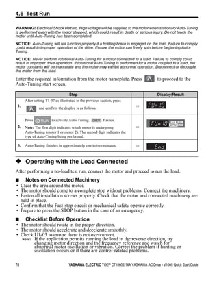
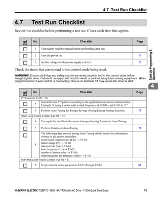
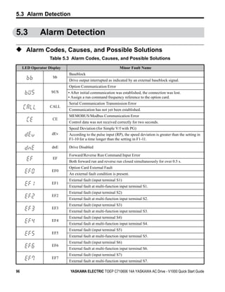
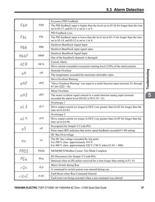
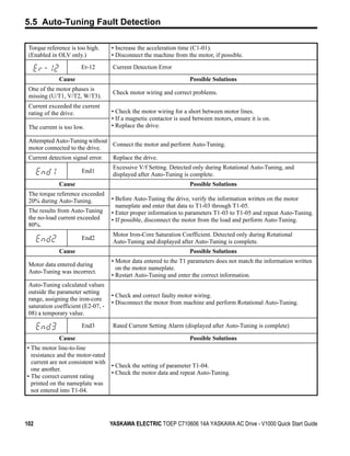
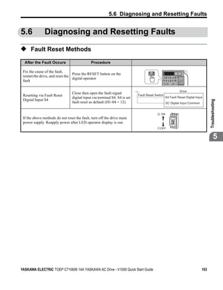
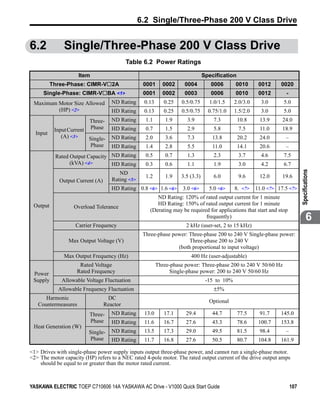
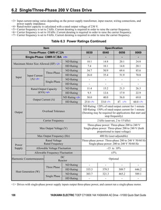
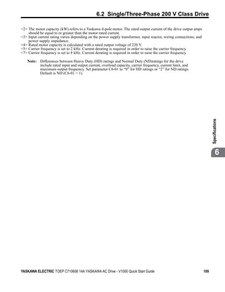
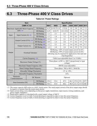
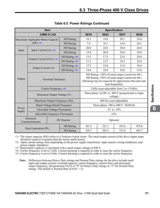
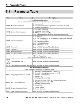
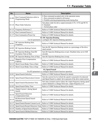
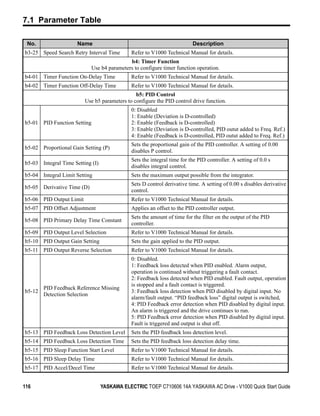
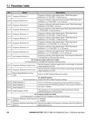
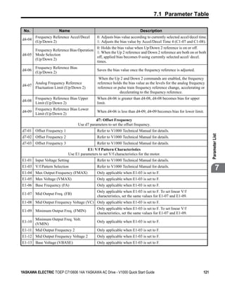
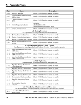
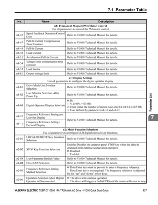
This quick start guide provides instructions for installation, start-up, programming, operation and troubleshooting of Yaskawa's AC Drive-V1000 compact vector control drive. The guide includes information on receiving and inspecting the drive, mechanical and electrical installation, basic programming for start-up and operation, specifications, parameter listings and standards compliance. Proper use and maintenance of the drive requires reading this manual in its entirety.

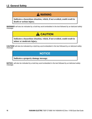
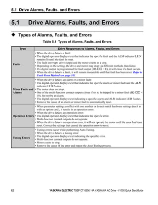
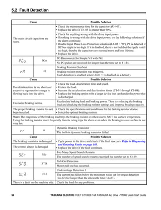
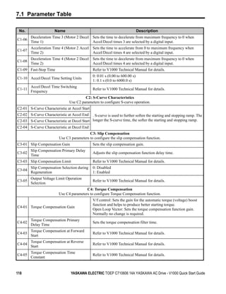
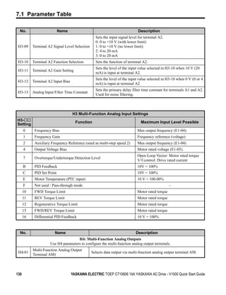
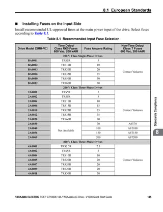
![8.1 European Standards
■ EMC Filters
The drive should be installed with the EMC filters listed below in order to comply with the
EN 61800-3, category C1 requirements.
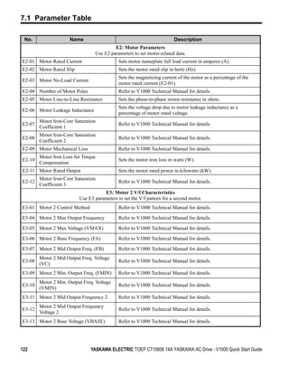
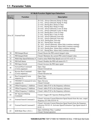
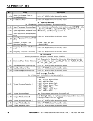
Table 8.2 EN 61800-3 Category C1 Filters
Filter Data (Manufacturer: Schaffner)
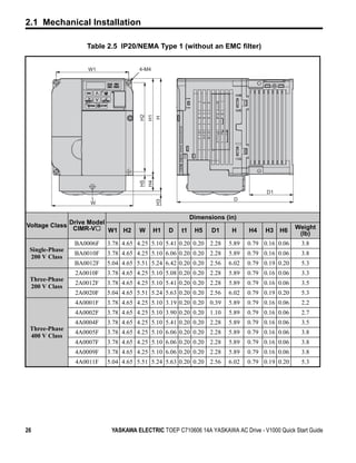
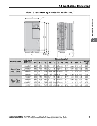
Drive Rated Drive Filter
CIMR-V Weight Dimensions
Type Current
[kg] [W × L × H] Y×X Mounting Mounting
[A] Screw A Screw
200 V Single-Phase Units
BA0001 FS 5855-10/07 10 0.4 71 × 169 × 45 51 × 156 M4 M5
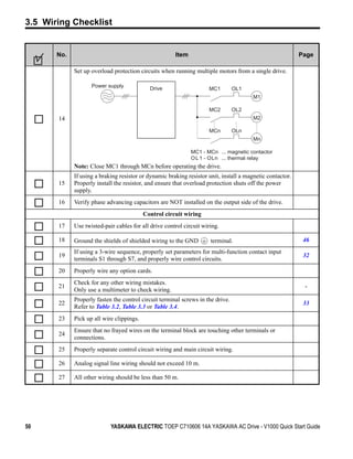
BA0002 FS 5855-10/07 10 0.4 71 × 169 × 45 51 × 156 M4 M5
BA0003 FS 5855-10/07 10 0.4 71 × 169 × 45 51 ×156 M4 M5
BA0006 FS 5855-20/07 20 0.7 111 × 169 × 50 91 × 156 M4 M5
BA0010 FS 5855-20/07 20 0.7 111 × 169 × 50 120 × 161 M4 M5
BA0012 FS 5855-30/07 30 1.0 144 × 174 × 50 120 × 161 M4 M5
200 V Three-Phase Units
2A0001 FS 5856-10-07 10 0.7 82 × 194 × 50 62 × 181 M4 M5
Standards Compliance
2A0002 FS 5856-10-07 10 0.7 82 × 194 × 50 62 × 181 M4 M5
2A0004 FS 5856-10-07 10 0.7 82 × 194 × 50 62 × 181 M4 M5
2A0006 FS 5856-10-07 10 0.7 82 × 194 × 50 62 × 181 M4 M5
2A0010 FS 5856-20-07 20 0.8 111 × 169 × 50 91 × 156 M4 M5
2A0012 FS 5856-20-07 20 0.8 111 × 169 × 50 91 × 156 M4 M5
2A0020 FS 5856-30-07 30 0.9 144 × 174 × 50 120 × 161 M4 M5
2A0030 FS 5973-35-07 35 1.4 141 × 330 × 46 115 × 313 M4 M5 8
2A0040 FS 5973-60-07 60 3.0 206 × 355 × 60 175 × 336 M5 M6
2A0056 FS 5973-60-07 60 3.0 206 × 355 × 60 175 × 336 M5 M6
2A0069 FS 5973-100-07 100 4.9 236 × 408 × 80 205 × 390 M8 M8
200 V Three-Phase Units
4A0001 FS 5857-5/07 5 0.5 111 × 169 × 45 91 × 156 M4 M5
4A0002 FS 5857-5/07 5 0.5 111 × 169 × 45 91 × 156 M4 M5
4A0004 FS 5857-10/07 10 0.75 111 × 169 × 45 91 × 156 M4 M5
4A0005 FS 5857-10/07 10 0.75 111 × 169 × 45 91 × 156 M4 M5
4A0007 FS 5857-10/07 10 0.75 111 × 169 × 45 91 × 156 M4 M5
4A0009 FS 5857-20/07 20 1.0 144 × 174 × 50 120 × 161 M4 M5
4A0011 FS 5857-20/07 20 1.0 144 × 174 × 50 120 × 161 M4 M5
YASKAWA ELECTRIC TOEP C710606 14A YASKAWA AC Drive - V1000 Quick Start Guide 149](https://image.slidesharecdn.com/v1000quickstartmanual-110104045500-phpapp01/85/V1000-quick-start-manual-149-320.jpg)
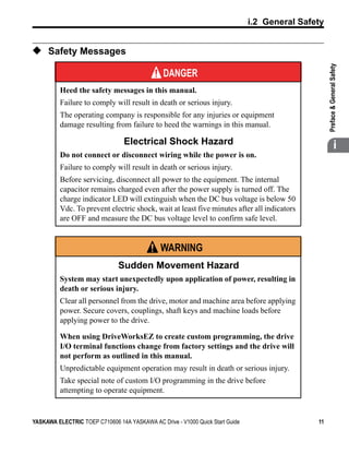
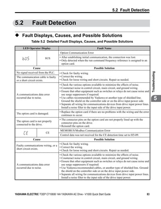
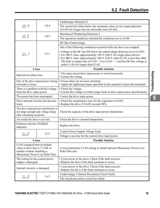
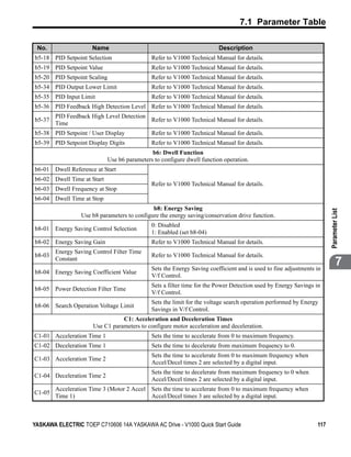
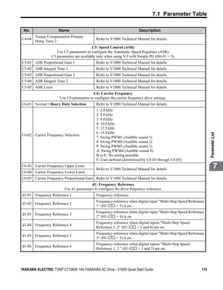
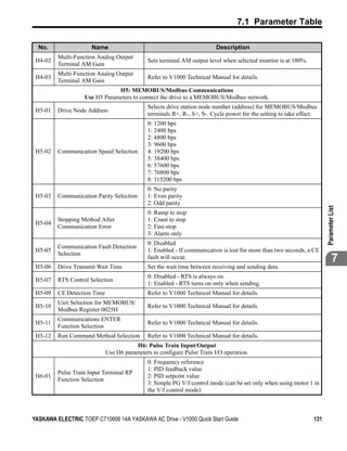
![8.1 European Standards
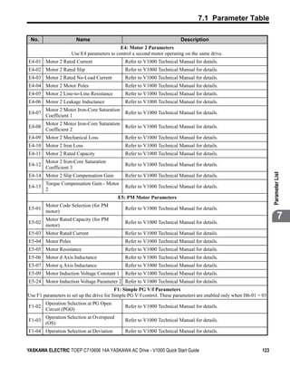
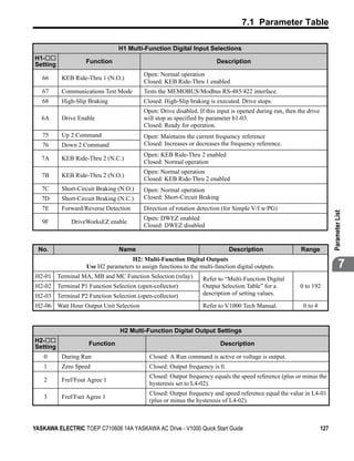
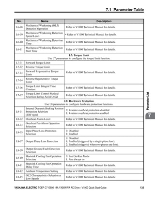
Filter Data (Manufacturer: Schaffner)
Drive Rated Drive Filter
CIMR-V Type Current Weight Dimensions
Y×X Mounting Mounting
[kg] [W × L × H]
[A] Screw A Screw
4A0018 FS 5857-30-07 30 2.0 184 × 304 × 56 150 × 288 M4 M5
4A0023 FS 5857-30-07 30 2.0 184 × 304 × 56 150 × 288 M4 M5
4A0031 FS 5972-35-07 35 2.1 206 × 355 × 50 175 × 336 M4 M5
4A0038 FS 5972-60-07 60 4.0 236 × 408 × 65 390 × 205 M6 M6
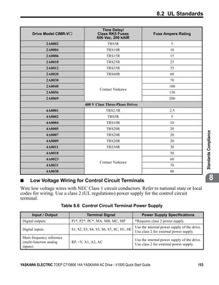
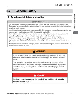
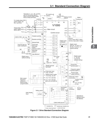
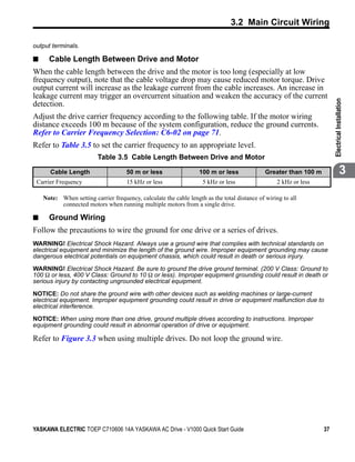
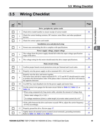
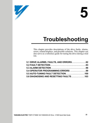
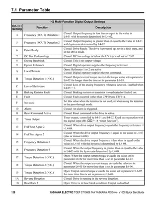
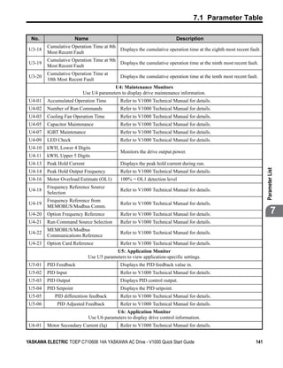
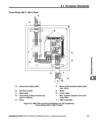
Figure 8.4
W H
Y
LINE
X
L
LOAD
A
PE
Figure 8.4 EMC Filter Dimensions
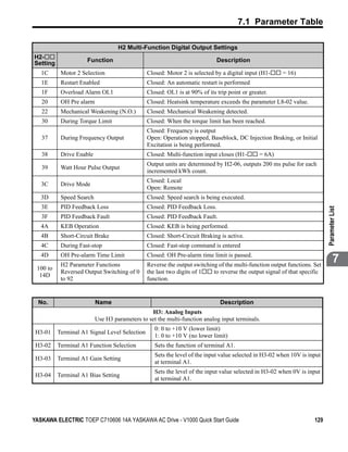
■ DC Reactors
Table 8.3 DC Reactors for Harmonics Reduction
Inverter Type DC Reactor
CIMR-Vo Model Rating
200V Three Phase Units
2A0004 5.4 A
UZDA-B
2A0006 8 mH
400 V Three Phase Units
4A0002 3.2 A
UZDA-B
4A0004 28 mH
Note: Contact Yaskawa for information about DC reactors for other models.
150 YASKAWA ELECTRIC TOEP C710606 14A YASKAWA AC Drive - V1000 Quick Start Guide](https://image.slidesharecdn.com/v1000quickstartmanual-110104045500-phpapp01/85/V1000-quick-start-manual-150-320.jpg)